US8029455B2 - Satiation pouches and methods of use - Google Patents
Satiation pouches and methods of use Download PDFInfo
- Publication number
- US8029455B2 US8029455B2 US12/398,917 US39891709A US8029455B2 US 8029455 B2 US8029455 B2 US 8029455B2 US 39891709 A US39891709 A US 39891709A US 8029455 B2 US8029455 B2 US 8029455B2
- Authority
- US
- United States
- Prior art keywords
- stomach
- pouch
- patient
- tissue
- stent
- Prior art date
- Legal status (The legal status is an assumption and is not a legal conclusion. Google has not performed a legal analysis and makes no representation as to the accuracy of the status listed.)
- Expired - Fee Related
Links
- 238000000034 method Methods 0.000 title claims abstract description 13
- 235000019553 satiation Nutrition 0.000 title claims abstract description 9
- 210000002784 stomach Anatomy 0.000 claims abstract description 46
- 210000003236 esophagogastric junction Anatomy 0.000 claims abstract description 11
- 239000000463 material Substances 0.000 claims description 30
- 210000003238 esophagus Anatomy 0.000 claims description 14
- 210000005070 sphincter Anatomy 0.000 claims description 4
- 208000008589 Obesity Diseases 0.000 claims description 2
- 229940088597 hormone Drugs 0.000 claims description 2
- 239000005556 hormone Substances 0.000 claims description 2
- 235000020824 obesity Nutrition 0.000 claims description 2
- 235000019627 satiety Nutrition 0.000 claims 2
- 230000036186 satiety Effects 0.000 claims 2
- 230000036528 appetite Effects 0.000 abstract 1
- 235000019789 appetite Nutrition 0.000 abstract 1
- 230000004888 barrier function Effects 0.000 description 34
- 238000007789 sealing Methods 0.000 description 9
- 210000000111 lower esophageal sphincter Anatomy 0.000 description 7
- 230000006870 function Effects 0.000 description 4
- 210000001198 duodenum Anatomy 0.000 description 3
- 239000004744 fabric Substances 0.000 description 3
- 235000003642 hunger Nutrition 0.000 description 3
- 238000002513 implantation Methods 0.000 description 3
- 229920000642 polymer Polymers 0.000 description 3
- 229920001296 polysiloxane Polymers 0.000 description 3
- 210000000813 small intestine Anatomy 0.000 description 3
- 239000010935 stainless steel Substances 0.000 description 3
- 229910001220 stainless steel Inorganic materials 0.000 description 3
- 239000000853 adhesive Substances 0.000 description 2
- 230000001070 adhesive effect Effects 0.000 description 2
- 230000037406 food intake Effects 0.000 description 2
- 235000012631 food intake Nutrition 0.000 description 2
- 208000021302 gastroesophageal reflux disease Diseases 0.000 description 2
- 229910001000 nickel titanium Inorganic materials 0.000 description 2
- HLXZNVUGXRDIFK-UHFFFAOYSA-N nickel titanium Chemical compound [Ti].[Ti].[Ti].[Ti].[Ti].[Ti].[Ti].[Ti].[Ti].[Ti].[Ti].[Ni].[Ni].[Ni].[Ni].[Ni].[Ni].[Ni].[Ni].[Ni].[Ni].[Ni].[Ni].[Ni].[Ni] HLXZNVUGXRDIFK-UHFFFAOYSA-N 0.000 description 2
- 229920000728 polyester Polymers 0.000 description 2
- 229920002635 polyurethane Polymers 0.000 description 2
- 239000004814 polyurethane Substances 0.000 description 2
- 210000001187 pylorus Anatomy 0.000 description 2
- 239000012858 resilient material Substances 0.000 description 2
- 230000035807 sensation Effects 0.000 description 2
- 235000019615 sensations Nutrition 0.000 description 2
- 239000012781 shape memory material Substances 0.000 description 2
- 229920000431 shape-memory polymer Polymers 0.000 description 2
- 230000004580 weight loss Effects 0.000 description 2
- 229920004934 Dacron® Polymers 0.000 description 1
- 229920000544 Gore-Tex Polymers 0.000 description 1
- 241000282412 Homo Species 0.000 description 1
- JVTAAEKCZFNVCJ-REOHCLBHSA-N L-lactic acid Chemical compound C[C@H](O)C(O)=O JVTAAEKCZFNVCJ-REOHCLBHSA-N 0.000 description 1
- 239000004677 Nylon Substances 0.000 description 1
- 210000003484 anatomy Anatomy 0.000 description 1
- 230000015572 biosynthetic process Effects 0.000 description 1
- 239000002131 composite material Substances 0.000 description 1
- 230000003247 decreasing effect Effects 0.000 description 1
- 239000013013 elastic material Substances 0.000 description 1
- 229920000295 expanded polytetrafluoroethylene Polymers 0.000 description 1
- 239000012530 fluid Substances 0.000 description 1
- 239000006260 foam Substances 0.000 description 1
- 238000003780 insertion Methods 0.000 description 1
- 230000037431 insertion Effects 0.000 description 1
- 210000001630 jejunum Anatomy 0.000 description 1
- 238000012986 modification Methods 0.000 description 1
- 230000004048 modification Effects 0.000 description 1
- 229920001778 nylon Polymers 0.000 description 1
- 229920001432 poly(L-lactide) Polymers 0.000 description 1
- 230000002787 reinforcement Effects 0.000 description 1
- 230000004044 response Effects 0.000 description 1
- 229910001285 shape-memory alloy Inorganic materials 0.000 description 1
- 239000000126 substance Substances 0.000 description 1
- 230000000153 supplemental effect Effects 0.000 description 1
- 238000012800 visualization Methods 0.000 description 1
Images


Classifications
-
- A—HUMAN NECESSITIES
- A61—MEDICAL OR VETERINARY SCIENCE; HYGIENE
- A61F—FILTERS IMPLANTABLE INTO BLOOD VESSELS; PROSTHESES; DEVICES PROVIDING PATENCY TO, OR PREVENTING COLLAPSING OF, TUBULAR STRUCTURES OF THE BODY, e.g. STENTS; ORTHOPAEDIC, NURSING OR CONTRACEPTIVE DEVICES; FOMENTATION; TREATMENT OR PROTECTION OF EYES OR EARS; BANDAGES, DRESSINGS OR ABSORBENT PADS; FIRST-AID KITS
- A61F5/00—Orthopaedic methods or devices for non-surgical treatment of bones or joints; Nursing devices; Anti-rape devices
- A61F5/0003—Apparatus for the treatment of obesity; Anti-eating devices
- A61F5/0013—Implantable devices or invasive measures
- A61F5/0076—Implantable devices or invasive measures preventing normal digestion, e.g. Bariatric or gastric sleeves
- A61F5/0079—Pyloric or esophageal obstructions
-
- A—HUMAN NECESSITIES
- A61—MEDICAL OR VETERINARY SCIENCE; HYGIENE
- A61F—FILTERS IMPLANTABLE INTO BLOOD VESSELS; PROSTHESES; DEVICES PROVIDING PATENCY TO, OR PREVENTING COLLAPSING OF, TUBULAR STRUCTURES OF THE BODY, e.g. STENTS; ORTHOPAEDIC, NURSING OR CONTRACEPTIVE DEVICES; FOMENTATION; TREATMENT OR PROTECTION OF EYES OR EARS; BANDAGES, DRESSINGS OR ABSORBENT PADS; FIRST-AID KITS
- A61F5/00—Orthopaedic methods or devices for non-surgical treatment of bones or joints; Nursing devices; Anti-rape devices
- A61F5/0003—Apparatus for the treatment of obesity; Anti-eating devices
- A61F5/0013—Implantable devices or invasive measures
- A61F5/0036—Intragastrical devices
-
- A—HUMAN NECESSITIES
- A61—MEDICAL OR VETERINARY SCIENCE; HYGIENE
- A61F—FILTERS IMPLANTABLE INTO BLOOD VESSELS; PROSTHESES; DEVICES PROVIDING PATENCY TO, OR PREVENTING COLLAPSING OF, TUBULAR STRUCTURES OF THE BODY, e.g. STENTS; ORTHOPAEDIC, NURSING OR CONTRACEPTIVE DEVICES; FOMENTATION; TREATMENT OR PROTECTION OF EYES OR EARS; BANDAGES, DRESSINGS OR ABSORBENT PADS; FIRST-AID KITS
- A61F5/00—Orthopaedic methods or devices for non-surgical treatment of bones or joints; Nursing devices; Anti-rape devices
- A61F5/0003—Apparatus for the treatment of obesity; Anti-eating devices
- A61F5/0013—Implantable devices or invasive measures
- A61F5/0076—Implantable devices or invasive measures preventing normal digestion, e.g. Bariatric or gastric sleeves
Definitions
- the present invention relates generally to the field of devices and methods for achieving weight loss in humans, and specifically to the use of devices implantable within the human stomach for controlling feelings of hunger and/or limiting food intake.
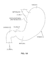
- FIG. 1A An anatomical view of a human stomach S and associated features is shown in FIG. 1A .
- the esophagus E delivers food from the mouth to the proximal portion of the stomach S.
- the z-line or gastro-esophageal junction Z is the irregularly-shaped border between the thin tissue of the esophagus and the thicker tissue of the stomach wall.
- the gastro-esophageal junction region G is the region encompassing the distal portion of the esophagus E, the z-line, and the proximal portion of the stomach S.
- Stomach S includes a fundus F at its proximal end and an antrum A at its distal end.
- Antrum A feeds into the pylorus P which attaches to the duodenum D, the proximal region of the small intestine.
- Within the pylorus P is a sphincter that prevents backflow of food from the duodenum D into the stomach.
- Prosthetic devices for use in controlling obesity are shown and described in U.S. application Ser. No. 09/940,110, filed Aug. 27, 2001 and U.S. application Ser. No. 10/118,289 filed Apr. 8, 2002, and U.S. Provisional Application No. 60/379,306 filed May 10, 2002.
- These applications are owned by the assignee of the present application, and the disclosures of these applications are incorporated herein by reference. Certain forms of these devices involve positioning a prosthetic pouch in the proximal stomach as shown in FIG. 1B .
- the pouch 2 includes a proximal opening 4 and a smaller distal opening 6 and forms a small reservoir that collects masticated food from the esophagus—thereby limiting the amount of food that can be consumed at one time. As the pouch fills with food, it may distend, imparting pressure against the upper stomach and lower esophageal sphincter causing the patient to experience sensations of fullness.
- the pouch may additionally or alternatively act as a restrictor, limiting the amount of food intake.
- the pouch is fixed in place using clips, sutures, suitable adhesives or other means 8 at anchor points around the perimeter of the proximal opening 4 .
- gaps 9 can occur along the perimeter of the pouch in regions between neighboring anchor points. Solving this problem is made more difficult by the flared geometry of the walls of the proximal stomach. Food entering or accumulating in the pouch 2 can ooze from these gaps and pass around the exterior of the pouch directly into the stomach, thereby decreasing the effectiveness of the prosthesis.
- the embodiments described herein optimize the function of the pouch devices by forming a barrier against passage of food through any such gaps and/or by eliminating such gaps.
- the present invention includes a prosthetic device positionable within the gastro-esophageal junction region of a patient, wherein the prosthetic device includes a proximal opening and a barrier device defining a central passage at least partially aligned with the proximal opening of the prosthetic device.
- the prosthetic device is attached to tissue of the gastro-esophageal region of the patient, with the device positioned such that food ingested by the patient passes from the esophagus through the central passage and proximal opening into the interior of the prosthetic device.
- the barrier contacts surrounding tissue and thereby minimizes passage of food from the esophagus around the exterior of the prosthetic device.
- the barrier is adaptable in response to movement of the surrounding tissue to maintain contact between the barrier and the surrounding tissue.
- FIG. 1A is a schematic illustration of a human stomach and a portion of the small intestine.
- FIG. 1B is a perspective view of a satiation pouch provided without supplemental barrier features. The pouch is shown positioned in the stomach.
- FIG. 1C is a top plan view of the satiation pouch of FIG. 1B shown within the stomach, and illustrating formation of gaps around the perimeter of the proximal opening.
- FIG. 2 is a perspective view of a first embodiment of a pouch having a circumferential barrier. The pouch is shown positioned in the stomach.
- FIG. 3 is a perspective view similar to FIG. 2 showing expansion of the barrier into contact with tissue in a stomach having relatively broad proximal dimensions.
- FIG. 4A is a top view of a pouch similar to the pouch of FIG. 2 showing the barrier and spring members restrained in a radially inward orientation.
- FIG. 4B is a side elevation view of the pouch of FIG. 4A .
- FIG. 5 is a perspective view similar to FIG. 2 showing a second embodiment having an alternative barrier configuration utilizing blade members.
- FIG. 6 is a perspective view similar to FIG. 2 showing a third embodiment having yet another barrier configuration utilizing a band of stent material.
- FIG. 7 is a perspective view similar to FIG. 2 showing a fourth embodiment having yet another barrier configuration utilizing leaf springs.
- FIG. 8A is a cross-sectional side elevation view of a fifth embodiment of a pouch, which has a proximal rim that forms a circumferential seal with adjacent body tissue.
- FIGS. 8B and 8C are cross-sectional side elevation views similar to FIG. 8A showing slight modifications to the rim position.
- FIG. 9A is a side elevation view of the pouch of FIG. 8A , showing the rim in the inverted position.
- FIG. 9B is a side elevation view similar to FIG. 9B , showing the rim moved to the non-inverted position and drawing tissue over a portion of the rim.
- FIG. 10A is a side elevation view of an alternative to the pouch of FIG. 9A , showing the rim in an everted position.
- FIG. 10B is a side elevation view similar to FIG. 10B , showing the rim moved to the non-everted position and drawing tissue inside a portion of the rim.
- FIG. 11 is a schematic illustration showing a sixth embodiment of a pouch, which utilizes a bellows structure to create a barrier.
- FIG. 12 is a schematic illustration showing a seventh embodiment of a pouch, which utilizes a conformable sealing ring.
- FIG. 13 is a schematic illustration showing an eighth embodiment of a pouch, which utilizes an inflatable sealing ring.
- FIG. 14 is a schematic illustration showing a ninth embodiment of a pouch having an expandable barrier stent.
- FIG. 15 is a schematic illustration shown a tenth embodiment of a pouch showing an alternative configuration of a barrier stent.
- the drawings show a number of embodiments of satiation pouches having features that create a barrier against passage of food through gaps occurring between the upper perimeter of the pouch and adjacent tissue and/or that minimize or eliminate such gaps.
- the barriers will form a seal with the adjacent tissue, however it is sufficient that the barriers prevent a substantial amount of food from passing between the exterior of the pouch and adjacent tissue, without necessarily forming an impermeable seal.
- the term “satiation devices” or “satiation pouches” will be used to mean devices or pouches intended to induce weight loss in one or more of a variety of ways. These include, but are not limited to, physically restricting the amount of food that can be consumed, and/or imparting pressure against portions of the body (e.g. stomach, esophagus, esophageal sphincter, etc) causing the patient to experience sensations of fullness, and/or affecting levels of hormones or other substances in the body that control or affect feelings of hunger, and/or affecting the amount of ingested food absorbed by the body.
- portions of the body e.g. stomach, esophagus, esophageal sphincter, etc
- the pouch of each described embodiment may be formed of a flexible material that will prevent passage of food through the sides of the pouch.
- a flexible material that will prevent passage of food through the sides of the pouch.
- materials include, but are not limited to polyesters (e.g. Dacron® polyester), ePTFE fabric (e.g. GoreTex® fabric or others), a polyurethane such as ChronoFlex® polyurethane, nylon fabrics, silicone, other polymeric materials, and bio-absorbable materials (e.g. PLLA, PGA, PCL, poly-amhydride etc).
- the material may be a composite of compliant, semi-compliant and/or non-compliant materials that give different regions of the pouch different degrees of compliance so as to allow/limit expansion of the pouch in various locations.
- the pouch may be desirable to provide the pouch with a fairly elastic exit port to as to prevent occlusion in the event a large piece of food is ingested and/or to control the exit pressure of food from the pouch, whereas the proximal end of the pouch may be stiffer to prevent bulging. Varying degrees of compliance may also be built into the pouch by varying the cross-sectional thickness in different regions of the pouch.
- the material may be coated with a lubricious, bio-compatible, chemically inert material, such as paraleyne, to reduce friction on the base material's surface which will help prevent sticking and food build up on the device.
- the flexible pouch material may be reinforced with, constructed of, or supported by supporting members, such as a soft mesh, a cage structure, ribs, rings etc.
- the supporting members may be formed of stainless steel, polymer, shape memory materials such as nitinol, shape memory alloys, or shape memory polymers, or thickened regions of material.
- the pouch may be constructed so as to be self-expanding, such that the pouch springs radially open into an expanded condition upon ejection from a deployment device or catheter.
- Implantation of the described devices is preferably performed endoscopically, by passing the devices through the esophagus, preferably under endoscopic visualization.
- the devices may be implanted using surgical or laparoscopic procedures.
- the pouch is secured at the gastro-esophageal junction region G using sutures, clips, adhesives, stents or stent-like structures, or other suitable means.
- sutures One suture attachment device found useful for applying sutures between the pouch and tissue is the “Sew-Right” suturing device available from LSI Solutions of Victor, N.Y.
- the pouch may be secured to the esophageal tissue, it is more preferable to apply sutures/clips below the Z-line to allow for attachment to the thicker tissue of the stomach wall.
- Each of the described pouches includes a proximal opening and a distal exit port (see openings 4 and 6 , respectively, of FIG. 1B ). Because of its small volume (which may be on the order of approximately 2 cc-300 cc in volume, but is preferably in the range of 10-30 cc), the pouch functions to limit the amount of food that can be consumed at one time. Over time the food within this reservoir descends into the stomach through the exit port.
- FIGS. 2 and 3 show a first embodiment of a pouch 10 having a proximal opening 12 , distal exit port or opening 14 and a passage extending between the proximal and distal openings.
- a resilient ring 16 surrounds the proximal opening 12 and a plurality of spring members 18 are attached to the ring 16 .
- Spring members 18 are preferably biased in a radially outward direction and can pivot relative to ring 16 .
- spring members 18 are preferably moveable independently of one another, they may take the form of multiple fingers formed along a single length of wire.
- Anchor loops 20 are positioned on the spring members 18 .
- the anchor loops 20 serve to receive sutures, clips or other attachment devices used to connect the pouch to surrounding tissue.
- the loops in each of the embodiments described in this application should be considered optional, since the pouch may alternatively be anchored directly to the tissue without the use of the loops 20 .
- the anchor loops 20 may be positioned in the outer apexes of the spring members as shown, and/or they may be positioned elsewhere such as closer to the ring 16 . See, for example, loops 20 a shown in dashed lines in FIG. 2 .
- Ring 16 , spring members 18 and loops 20 are preferably made of a resilient material (e.g. stainless steel, polymers etc.) suitable for use within the body.
- Webbing 22 is connected to the spring members 18 along the circumference of the ring 16 to form a skirt-like member having a central opening.
- Webbing 22 is preferably formed of a flexible material that is substantially impermeable to masticated food.
- the material may be inelastic or elastic. Examples of suitable materials for the webbing 22 include those listed above for use with the pouch.
- the webbing 22 and spring members 18 are preferably configured to form a dynamic seal with the surrounding tissue, so as to maintain a substantially consistent barrier despite stomach movement and flexure of the pouch.
- the webbing 22 may be made expandable by using an elastic material and/or by including pleats in the webbing that allow for expansion.
- the spring members 18 are preferably independently moveable and thus contribute to the dynamic nature of the barrier.
- the ring 16 and/or spring members 18 may be eliminated and the material of the webbing 22 itself may provide the necessary spring properties.
- both the pouch and webbing, or the webbing along may be formed of a resilient silicone or other resilient material.
- pouch 10 is introduced into the stomach S via the esophagus E and is held in the desired attachment location in the gastro-esophageal junction region.
- the pouch is anchored in place such as by connecting sutures or other attachment means to plurality of the anchor loops 20 / 20 a or directly to the pouch and/or webbing to secure the pouch 10 in position.
- the outward radial forces of spring members 18 cause the spring members 18 to extend radially outwardly, carrying the webbing 22 into contact with the surrounding tissue, creating a barrier that minimizes passage of food around the pouch.
- the spring members 18 will cause the webbing 22 to flare outwardly into contact with the surrounding tissue as shown in FIG. 3 .
- a narrower proximal stomach may restrict outward movement of the spring members 18 such that they angle the webbing in a slight inward direction.
- the spring members 18 may be held in a laterally inward position as shown in FIGS. 4A and 4B during positioning of the pouch within the stomach.
- temporary sutures 24 may be threaded through loops 20 and cinched to draw spring members 18 into the position shown in FIG. 4A .
- FIG. 4B when drawn inwardly the spring members 18 and webbing 22 may have a relatively flat profile.
- the pouch may be anchored into position with the spring members 18 and pouch in the inward position, such as by attaching sutures to the loops 20 as described above, or by attaching sutures to additional anchor loops 26 that are separate from the spring members 18 .
- temporary sutures 24 are snipped so as to release spring members 18 , allowing the spring members 18 to carry the webbing into contact with the surrounding tissue.
- FIG. 5 A second embodiment of a pouch 30 is shown in FIG. 5 .
- the second embodiment differs from the first embodiment primarily in that a plurality of blades 32 are mounted to resilient ring 34 .
- Blades 32 may be formed of a variety of materials, including those listed above for forming the pouch.
- the blades are outwardly biased using wire reinforcements or other biasing structure.
- Anchors 36 are preferably positioned in spaced-apart locations between the blades 32 .
- the pouch 30 is sutured in place by attaching sutures between anchors 36 and adjacent tissue.
- the blades 32 spring outwardly into contact with surrounding tissue, thereby creating a seal or barrier against passage of food that might otherwise pass between gaps forming between anchor points.
- FIG. 6 shows a third embodiment of a pouch 40 , which uses an expandable stent-like band 42 for creating a seal or barrier.
- Band 42 is outwardly biased and may be formed of self-expanding material, such as stainless steel or a shape memory material such as nitinol or shape-memory polymer, and may be formed as a soft mesh or other framework formed of such materials in combination.
- the mesh may be created to have sufficiently small spaces between strands to form an effective barrier against a substantial portion of the ingested food, or it may be provided with a polymeric barrier that prevents ingested food from passing through the walls of the band 42 .
- the polymeric barrier may be a skin. formed on the exterior or interior of the mesh, or the mesh may be encapsulated in polymeric material or the polymer may be disposed in the interstices of the mesh.
- the pouch 40 is secured in place by attaching sutures between anchors 44 and adjacent tissue of the gastro-esophageal junction region.
- Band 42 then expands into contact with the surround tissue to form the seal or barrier.
- the band 42 is preferably positioned beyond the lower esophageal sphincter (identified as LES in FIG. 6 ) to avoid interference with proper sphincter function.
- a fourth embodiment of a pouch 50 is similar to the previously described embodiments except that a plurality of leaf springs 52 are attached at the proximal end of the pouch. Springs 52 are outwardly biased to create the seal or barrier with surrounding tissue.
- the pouch may include a resilient ring 54 , and the pouch may be attached to surrounding tissue using sutures passed through anchors 56 .
- springs 52 may be coil springs which may be connected to a common structure at their proximal ends, or which may have free proximal ends.
- a fifth embodiment of a pouch 60 includes an enlarged rim 62 surrounding the proximal opening 64 of the pouch 60 .
- Rim 62 may extend slightly outwardly from the external surface of the pouch as shown in FIG. 8A , or slightly inwardly as shown in FIG. 8B , or both as shown in FIG. 8C .
- anchor loops 66 extend from a distal portion of the rim 62 as shown in FIG. 8A .
- the rim 62 is inverted inside the pouch 60 to the position shown in FIG. 9A . Once the rim has been inverted, anchor loops 66 extend in a proximal direction as shown.
- the pouch 60 is inserted into the stomach and the anchor loops 66 are secured to tissue using sutures or other attachment means.
- the rim 62 is returned to the non-inverted position shown in FIG. 9B , causing the anchor loops 66 to return to the distally-oriented position.
- the loops 66 pull the attached tissue in a distal direction, around the edges of the rim 62 , creating a taut and leak-resistant seal around the rim.
- anchors 66 extend distally on an interior portion of the rim as shown in FIG. 8B .
- the rim 62 is everted outside the pouch 60 to the position shown in FIG. 10 A—causing anchor loops 66 to extend in a proximal direction as shown.
- the pouch 60 is inserted into the stomach and the anchor loops 66 are secured to tissue using sutures or other attachment means.
- the rim 62 is returned to the non-everted position shown in FIG. 10B , causing the anchor loops 66 to return to the distally-oriented position.
- the loops 66 pull the attached tissue in a distal direction, inside the edges of the rim 62 , again creating a seal around the rim.
- FIG. 11 shows a sixth embodiment of a pouch 70 , which includes an expandable bellows structure 72 , attached to a resilient ring 74 .
- Bellows structure 72 includes a central channel 76 in alignment with the proximal opening (not shown) of the pouch 70 , and is preferably formed of a flexible material that is substantially impervious to masticated food, and may be formed of materials similar to those listed for use in constructing the pouch. It may have a substantially cylindrical shape or a tapered geometry such as that shown in FIG. 11 .
- a sealing ring 78 formed of a flexible material capable of forming a seal when urged into contact with body tissue.
- Anchors 79 are attached to resilient ring 74 and are used to receive sutures, clips, etc that will connect the pouch to surrounding body tissue.
- the proximal portion of the pouch 80 includes a conformable sealing ring 82 made of foam, sponge, silicone, or other conformable material that will seal against surrounding tissue when pressed into contact with the tissue.
- Ring 82 includes a central channel 84 and may include a cylindrical or tapered geometry.
- Anchors 86 receive sutures or clips used to fix the pouch to body tissue.
- the eighth embodiment of FIG. 13 is a pouch 90 having a conformable sealing ring 92 .
- Sealing ring 92 is formed of an elastic or inelastic bladder inflatable using an inflation fluid or gas.
- the bladder may be inflated prior to insertion into the stomach, or it may include a detachable inflation valve (not shown) that may be used to introduce inflation medium into the bladder after the pouch has been fixed within the stomach.
- the sealing ring 92 may have a cylindrical or tapered geometry. Ingested food flows through a central channel 94 in the sealing ring 92 and into the pouch 90 .
- FIGS. 14 and 15 show ninth and tenth embodiments, respectively, of pouches having barrier devices for minimizing passage of food around, rather than through, the pouch. These embodiments are similar to the FIG. 6 embodiment in that they utilize a stent-like structure to expand against surrounding tissue to create the barrier or seal.
- the barrier provided with the pouch 100 of FIG. 14 differs from that of FIG. 6 in that band 102 of stent material extends further into the esophagus, creating a seal with the tissue of the esophagus. This seal may be above, below, or within the lower esophageal sphincter (LES).
- anchors 104 receive sutures or clips that are used to fix the device to tissue in the region.
- a flexible tubular member 114 extends between the band 112 of stent material and the pouch 110 .
- member 114 may be positioned within the LES region while still preserving function of the LES.
Abstract
Description
Claims (8)
Priority Applications (4)
| Application Number | Priority Date | Filing Date | Title |
|---|---|---|---|
| US12/398,917 US8029455B2 (en) | 2003-01-16 | 2009-03-05 | Satiation pouches and methods of use |
| US13/236,431 US20120004590A1 (en) | 2003-01-16 | 2011-09-19 | Satiation pouches and methods of use |
| US14/522,214 US9358145B2 (en) | 2003-01-16 | 2014-10-23 | Satiation pouches and methods of use |
| US15/150,784 US9827130B2 (en) | 2003-01-16 | 2016-05-10 | Implantable devices having a radially expandable barrier and related methods of use |
Applications Claiming Priority (2)
| Application Number | Priority Date | Filing Date | Title |
|---|---|---|---|
| US10/345,666 US20040143342A1 (en) | 2003-01-16 | 2003-01-16 | Satiation pouches and methods of use |
| US12/398,917 US8029455B2 (en) | 2003-01-16 | 2009-03-05 | Satiation pouches and methods of use |
Related Parent Applications (1)
| Application Number | Title | Priority Date | Filing Date |
|---|---|---|---|
| US10/345,666 Division US20040143342A1 (en) | 2003-01-16 | 2003-01-16 | Satiation pouches and methods of use |
Related Child Applications (1)
| Application Number | Title | Priority Date | Filing Date |
|---|---|---|---|
| US13/236,431 Continuation US20120004590A1 (en) | 2003-01-16 | 2011-09-19 | Satiation pouches and methods of use |
Publications (2)
| Publication Number | Publication Date |
|---|---|
| US20090177215A1 US20090177215A1 (en) | 2009-07-09 |
| US8029455B2 true US8029455B2 (en) | 2011-10-04 |
Family
ID=32711974
Family Applications (5)
| Application Number | Title | Priority Date | Filing Date |
|---|---|---|---|
| US10/345,666 Abandoned US20040143342A1 (en) | 2003-01-16 | 2003-01-16 | Satiation pouches and methods of use |
| US12/398,917 Expired - Fee Related US8029455B2 (en) | 2003-01-16 | 2009-03-05 | Satiation pouches and methods of use |
| US13/236,431 Abandoned US20120004590A1 (en) | 2003-01-16 | 2011-09-19 | Satiation pouches and methods of use |
| US14/522,214 Expired - Lifetime US9358145B2 (en) | 2003-01-16 | 2014-10-23 | Satiation pouches and methods of use |
| US15/150,784 Expired - Fee Related US9827130B2 (en) | 2003-01-16 | 2016-05-10 | Implantable devices having a radially expandable barrier and related methods of use |
Family Applications Before (1)
| Application Number | Title | Priority Date | Filing Date |
|---|---|---|---|
| US10/345,666 Abandoned US20040143342A1 (en) | 2003-01-16 | 2003-01-16 | Satiation pouches and methods of use |
Family Applications After (3)
| Application Number | Title | Priority Date | Filing Date |
|---|---|---|---|
| US13/236,431 Abandoned US20120004590A1 (en) | 2003-01-16 | 2011-09-19 | Satiation pouches and methods of use |
| US14/522,214 Expired - Lifetime US9358145B2 (en) | 2003-01-16 | 2014-10-23 | Satiation pouches and methods of use |
| US15/150,784 Expired - Fee Related US9827130B2 (en) | 2003-01-16 | 2016-05-10 | Implantable devices having a radially expandable barrier and related methods of use |
Country Status (5)
| Country | Link |
|---|---|
| US (5) | US20040143342A1 (en) |
| EP (1) | EP1585458A1 (en) |
| JP (1) | JP2006512985A (en) |
| AU (1) | AU2003286612A1 (en) |
| WO (1) | WO2004064680A1 (en) |
Cited By (41)
| Publication number | Priority date | Publication date | Assignee | Title |
|---|---|---|---|---|
| US20100030017A1 (en) * | 2007-02-14 | 2010-02-04 | Bkfw,Llc | Bariatric device and method |
| US20100198237A1 (en) * | 2007-02-14 | 2010-08-05 | Sentinel Group, Llc | Mucosal capture fixation of medical device |
| US20110092879A1 (en) * | 2004-10-15 | 2011-04-21 | Bfkw,Llc | Bariatric device and method |
| US20110153030A1 (en) * | 2001-08-27 | 2011-06-23 | Synecor, Llc | Positioning tools and methods for implanting medical devices |
| US20110270410A1 (en) * | 2001-08-27 | 2011-11-03 | Barosense, Inc. | Satiation devices and methods |
| US20120004590A1 (en) * | 2003-01-16 | 2012-01-05 | Barosense, Inc | Satiation pouches and methods of use |
| US20120053504A1 (en) * | 2004-09-27 | 2012-03-01 | Valentx, Inc. | Methods for attachment of a gastrointestinal sleeve |
| US8834553B2 (en) | 2009-09-11 | 2014-09-16 | Gi Dynamics, Inc. | Anchors with biodegradable constraints |
| US8864840B2 (en) | 2010-10-19 | 2014-10-21 | Apollo Endosurgery, Inc. | Intragastric implants with collapsible frames |
| US8870966B2 (en) | 2010-10-18 | 2014-10-28 | Apollo Endosurgery, Inc. | Intragastric balloon for treating obesity |
| US8920447B2 (en) | 2010-10-19 | 2014-12-30 | Apollo Endosurgery, Inc. | Articulated gastric implant clip |
| US8956318B2 (en) | 2012-05-31 | 2015-02-17 | Valentx, Inc. | Devices and methods for gastrointestinal bypass |
| US8956380B2 (en) | 2010-10-18 | 2015-02-17 | Apollo Endosurgery, Inc. | Reactive intragastric implant devices |
| US9011365B2 (en) | 2013-03-12 | 2015-04-21 | Medibotics Llc | Adjustable gastrointestinal bifurcation (AGB) for reduced absorption of unhealthy food |
| US9055998B2 (en) | 2004-10-15 | 2015-06-16 | Bfkw, Llc | Bariatric device and method for recipient with altered anatomy |
| US9067070B2 (en) | 2013-03-12 | 2015-06-30 | Medibotics Llc | Dysgeusia-inducing neurostimulation for modifying consumption of a selected nutrient type |
| US9072579B2 (en) | 2009-10-21 | 2015-07-07 | Apollo Endosurgery, Inc. | Bariatric device and method for weight loss |
| US9095405B2 (en) | 2010-10-19 | 2015-08-04 | Apollo Endosurgery, Inc. | Space-filling intragastric implants with fluid flow |
| US9155650B2 (en) | 2010-03-15 | 2015-10-13 | Apollo Endosurgery, Inc. | Bariatric device and method for weight loss |
| US9198790B2 (en) | 2010-10-19 | 2015-12-01 | Apollo Endosurgery, Inc. | Upper stomach gastric implants |
| US20150374484A1 (en) * | 2014-06-26 | 2015-12-31 | Boston Scientific Scimed, Inc. | Medical devices and methods to prevent bile reflux after bariatric procedures |
| US9233016B2 (en) | 2010-10-18 | 2016-01-12 | Apollo Endosurgery, Inc. | Elevating stomach stimulation device |
| US20160022460A1 (en) * | 2012-01-23 | 2016-01-28 | Apollo Endosurgery, Inc. | Endolumenal Esophageal Restriction Device |
| US9265596B2 (en) | 2009-09-11 | 2016-02-23 | Gi Dynamics, Inc. | Anchors with open heads |
| US9375338B2 (en) | 2011-05-20 | 2016-06-28 | Bfkw, Llc | Intraluminal device and method with enhanced anti-migration |
| US9398969B2 (en) | 2010-10-19 | 2016-07-26 | Apollo Endosurgery, Inc. | Upper stomach gastric implants |
| US9445791B2 (en) | 2003-10-10 | 2016-09-20 | Boston Scientific Scimed, Inc. | Systems and methods related to gastro-esophageal implants |
| US9451960B2 (en) | 2012-05-31 | 2016-09-27 | Valentx, Inc. | Devices and methods for gastrointestinal bypass |
| US9456916B2 (en) | 2013-03-12 | 2016-10-04 | Medibotics Llc | Device for selectively reducing absorption of unhealthy food |
| US9463107B2 (en) | 2010-10-18 | 2016-10-11 | Apollo Endosurgery, Inc. | Variable size intragastric implant devices |
| US9498365B2 (en) | 2010-10-19 | 2016-11-22 | Apollo Endosurgery, Inc. | Intragastric implants with multiple fluid chambers |
| US9545326B2 (en) | 2012-03-06 | 2017-01-17 | Bfkw, Llc | Intraluminal device delivery technique |
| US9561127B2 (en) | 2002-11-01 | 2017-02-07 | Valentx, Inc. | Apparatus and methods for treatment of morbid obesity |
| US9668901B2 (en) | 2010-10-18 | 2017-06-06 | Apollo Endosurgery Us, Inc. | Intragastric implants with duodenal anchors |
| US9675489B2 (en) | 2012-05-31 | 2017-06-13 | Valentx, Inc. | Devices and methods for gastrointestinal bypass |
| US9757264B2 (en) | 2013-03-13 | 2017-09-12 | Valentx, Inc. | Devices and methods for gastrointestinal bypass |
| US10070980B2 (en) | 2010-10-19 | 2018-09-11 | Apollo Endosurgery Us, Inc. | Anchored non-piercing duodenal sleeve and delivery systems |
| US10271940B2 (en) | 2014-12-29 | 2019-04-30 | Bfkw, Llc | Fixation of intraluminal device |
| US10350101B2 (en) | 2002-11-01 | 2019-07-16 | Valentx, Inc. | Devices and methods for endolumenal gastrointestinal bypass |
| US11013629B2 (en) | 2014-12-29 | 2021-05-25 | Bfkw, Llc | Fixation of intraluminal device |
| US11020213B2 (en) | 2014-12-29 | 2021-06-01 | Bfkw, Llc | Fixation of intraluminal device |
Families Citing this family (105)
| Publication number | Priority date | Publication date | Assignee | Title |
|---|---|---|---|---|
| CA2409512A1 (en) * | 2000-05-08 | 2001-11-15 | Qtl Biosystems Llc | Improvements to the fluorescent polymer-qtl approach to biosensing |
| WO2002091961A1 (en) * | 2001-05-17 | 2002-11-21 | Wilson-Cook Medical, Inc. | Intragastric device for treating obesity |
| US7087088B2 (en) * | 2001-05-24 | 2006-08-08 | Torax Medical, Inc. | Methods and apparatus for regulating the flow of matter through body tubing |
| US6675809B2 (en) | 2001-08-27 | 2004-01-13 | Richard S. Stack | Satiation devices and methods |
| US20040117031A1 (en) * | 2001-08-27 | 2004-06-17 | Stack Richard S. | Satiation devices and methods |
| US6845776B2 (en) * | 2001-08-27 | 2005-01-25 | Richard S. Stack | Satiation devices and methods |
| US7146984B2 (en) * | 2002-04-08 | 2006-12-12 | Synecor, Llc | Method and apparatus for modifying the exit orifice of a satiation pouch |
| US7695427B2 (en) | 2002-04-26 | 2010-04-13 | Torax Medical, Inc. | Methods and apparatus for treating body tissue sphincters and the like |
| US20050197715A1 (en) * | 2002-04-26 | 2005-09-08 | Torax Medical, Inc. | Methods and apparatus for implanting devices into non-sterile body lumens or organs |
| US20090149871A9 (en) * | 2002-11-01 | 2009-06-11 | Jonathan Kagan | Devices and methods for treating morbid obesity |
| US7794447B2 (en) | 2002-11-01 | 2010-09-14 | Valentx, Inc. | Gastrointestinal sleeve device and methods for treatment of morbid obesity |
| US7837669B2 (en) | 2002-11-01 | 2010-11-23 | Valentx, Inc. | Devices and methods for endolumenal gastrointestinal bypass |
| US7037344B2 (en) * | 2002-11-01 | 2006-05-02 | Valentx, Inc. | Apparatus and methods for treatment of morbid obesity |
| EP1569582B1 (en) | 2002-12-02 | 2017-05-31 | GI Dynamics, Inc. | Bariatric sleeve |
| US7608114B2 (en) | 2002-12-02 | 2009-10-27 | Gi Dynamics, Inc. | Bariatric sleeve |
| US7025791B2 (en) | 2002-12-02 | 2006-04-11 | Gi Dynamics, Inc. | Bariatric sleeve |
| US7695446B2 (en) | 2002-12-02 | 2010-04-13 | Gi Dynamics, Inc. | Methods of treatment using a bariatric sleeve |
| US7678068B2 (en) | 2002-12-02 | 2010-03-16 | Gi Dynamics, Inc. | Atraumatic delivery devices |
| US7766973B2 (en) * | 2005-01-19 | 2010-08-03 | Gi Dynamics, Inc. | Eversion resistant sleeves |
| US7291160B2 (en) * | 2003-03-17 | 2007-11-06 | Delegge Rebecca | Intragastric catheter |
| US7314489B2 (en) * | 2003-08-20 | 2008-01-01 | Ethicon Endo-Surgery, Inc. | Method and apparatus to facilitate nutritional malabsorption |
| US20050247320A1 (en) | 2003-10-10 | 2005-11-10 | Stack Richard S | Devices and methods for retaining a gastro-esophageal implant |
| US7070616B2 (en) * | 2003-10-31 | 2006-07-04 | Cordis Corporation | Implantable valvular prosthesis |
| US7815589B2 (en) | 2003-12-09 | 2010-10-19 | Gi Dynamics, Inc. | Methods and apparatus for anchoring within the gastrointestinal tract |
| US8057420B2 (en) | 2003-12-09 | 2011-11-15 | Gi Dynamics, Inc. | Gastrointestinal implant with drawstring |
| US7717843B2 (en) | 2004-04-26 | 2010-05-18 | Barosense, Inc. | Restrictive and/or obstructive implant for inducing weight loss |
| WO2006016894A1 (en) | 2004-07-09 | 2006-02-16 | Gi Dynamics, Inc. | Methods and devices for placing a gastrointestinal sleeve |
| AU2005287010B2 (en) | 2004-09-17 | 2010-04-15 | Gi Dynamics, Inc. | Gastrointestinal anchor |
| EP1669045B1 (en) * | 2004-12-09 | 2012-04-11 | AMI Agency for Medical Innovations GmbH | Gastric band for the treatment of obesity |
| US7771382B2 (en) * | 2005-01-19 | 2010-08-10 | Gi Dynamics, Inc. | Resistive anti-obesity devices |
| US20060252983A1 (en) * | 2005-02-11 | 2006-11-09 | Lembo Nicholas J | Dynamically adjustable gastric implants and methods of treating obesity using dynamically adjustable gastric implants |
| US7785291B2 (en) * | 2005-03-01 | 2010-08-31 | Tulip Medical Ltd. | Bioerodible self-deployable intragastric implants |
| US7699863B2 (en) | 2005-03-01 | 2010-04-20 | Tulip Medical Ltd. | Bioerodible self-deployable intragastric implants |
| WO2006107901A1 (en) * | 2005-04-04 | 2006-10-12 | Micardia Corporation | Dynamic reinforcement of the lower esophageal sphincter |
| WO2006122019A2 (en) * | 2005-05-09 | 2006-11-16 | Wilson-Cook Medical, Inc. | Intragastric device for treating obesity |
| US7666180B2 (en) * | 2005-05-20 | 2010-02-23 | Tyco Healthcare Group Lp | Gastric restrictor assembly and method of use |
| US7691053B2 (en) * | 2005-05-20 | 2010-04-06 | Tyco Healthcare Group Lp | Gastric restrictor assembly and method of use |
| US20060264982A1 (en) * | 2005-05-20 | 2006-11-23 | Viola Frank J | Gastric restrictor assembly and method of use |
| US7976488B2 (en) | 2005-06-08 | 2011-07-12 | Gi Dynamics, Inc. | Gastrointestinal anchor compliance |
| CA2611477C (en) | 2005-06-10 | 2012-01-17 | Wilson-Cook Medical, Inc. | Cautery catheter |
| US9055942B2 (en) | 2005-10-03 | 2015-06-16 | Boston Scienctific Scimed, Inc. | Endoscopic plication devices and methods |
| US20070123994A1 (en) * | 2005-11-29 | 2007-05-31 | Ethicon Endo-Surgery, Inc. | Internally Placed Gastric Restriction Device |
| US8216268B2 (en) * | 2005-12-22 | 2012-07-10 | Cook Medical Technologies Llc | Intragastric bag for treating obesity |
| JP5021675B2 (en) * | 2005-12-22 | 2012-09-12 | クック メディカル テクノロジーズ エルエルシー | Coil-like intragastric member for the treatment of obesity |
| WO2007127209A2 (en) | 2006-04-25 | 2007-11-08 | Valentx, Inc. | Methods and devices for gastrointestinal stimulation |
| US7819836B2 (en) | 2006-06-23 | 2010-10-26 | Gi Dynamics, Inc. | Resistive anti-obesity devices |
| US8109895B2 (en) * | 2006-09-02 | 2012-02-07 | Barosense, Inc. | Intestinal sleeves and associated deployment systems and methods |
| EP2068719B1 (en) | 2006-09-15 | 2017-10-25 | Boston Scientific Scimed, Inc. | System for anchoring stomach implant |
| WO2008039800A2 (en) | 2006-09-25 | 2008-04-03 | Valentx, Inc. | Toposcopic access and delivery devices |
| US20080161929A1 (en) | 2006-12-29 | 2008-07-03 | Mccormack Bruce | Cervical distraction device |
| US8801647B2 (en) | 2007-02-22 | 2014-08-12 | Gi Dynamics, Inc. | Use of a gastrointestinal sleeve to treat bariatric surgery fistulas and leaks |
| US8007507B2 (en) * | 2007-05-10 | 2011-08-30 | Cook Medical Technologies Llc | Intragastric bag apparatus and method of delivery for treating obesity |
| EP2164558A4 (en) | 2007-06-08 | 2010-08-04 | Valentx Inc | Methods and devices for intragastric support of functional or prosthetic gastrointestinal devices |
| US8435203B2 (en) * | 2007-06-20 | 2013-05-07 | Covidien Lp | Gastric restrictor assembly and method of use |
| US20090030284A1 (en) | 2007-07-18 | 2009-01-29 | David Cole | Overtube introducer for use in endoscopic bariatric surgery |
| JP5581209B2 (en) | 2007-07-18 | 2014-08-27 | ボストン サイエンティフィック サイムド,インコーポレイテッド | Endoscopic implant system |
| US20090149879A1 (en) * | 2007-12-10 | 2009-06-11 | Dillon Travis E | Dynamic volume displacement weight loss device |
| US7883524B2 (en) * | 2007-12-21 | 2011-02-08 | Wilson-Cook Medical Inc. | Method of delivering an intragastric device for treating obesity |
| US8016851B2 (en) * | 2007-12-27 | 2011-09-13 | Cook Medical Technologies Llc | Delivery system and method of delivery for treating obesity |
| US20090171383A1 (en) | 2007-12-31 | 2009-07-02 | David Cole | Gastric space occupier systems and methods of use |
| US9005288B2 (en) | 2008-01-09 | 2015-04-14 | Providence Medical Techonlogy, Inc. | Methods and apparatus for accessing and treating the facet joint |
| US8020741B2 (en) | 2008-03-18 | 2011-09-20 | Barosense, Inc. | Endoscopic stapling devices and methods |
| US8267966B2 (en) | 2008-06-06 | 2012-09-18 | Providence Medical Technology, Inc. | Facet joint implants and delivery tools |
| US11224521B2 (en) | 2008-06-06 | 2022-01-18 | Providence Medical Technology, Inc. | Cervical distraction/implant delivery device |
| US9333086B2 (en) | 2008-06-06 | 2016-05-10 | Providence Medical Technology, Inc. | Spinal facet cage implant |
| US8361152B2 (en) | 2008-06-06 | 2013-01-29 | Providence Medical Technology, Inc. | Facet joint implants and delivery tools |
| CA2725811A1 (en) | 2008-06-06 | 2009-12-10 | Providence Medical Technology, Inc. | Facet joint implants and delivery tools |
| WO2010021743A1 (en) * | 2008-08-21 | 2010-02-25 | Sentinel Group, Llc | Gastro-esophageal device and method |
| US8579987B2 (en) * | 2008-10-10 | 2013-11-12 | Milux Holding Sa | Artificial stomach |
| US7934631B2 (en) | 2008-11-10 | 2011-05-03 | Barosense, Inc. | Multi-fire stapling systems and methods for delivering arrays of staples |
| US8211186B2 (en) | 2009-04-03 | 2012-07-03 | Metamodix, Inc. | Modular gastrointestinal prostheses |
| US8702641B2 (en) | 2009-04-03 | 2014-04-22 | Metamodix, Inc. | Gastrointestinal prostheses having partial bypass configurations |
| US9278019B2 (en) | 2009-04-03 | 2016-03-08 | Metamodix, Inc | Anchors and methods for intestinal bypass sleeves |
| US9173760B2 (en) | 2009-04-03 | 2015-11-03 | Metamodix, Inc. | Delivery devices and methods for gastrointestinal implants |
| US8961539B2 (en) | 2009-05-04 | 2015-02-24 | Boston Scientific Scimed, Inc. | Endoscopic implant system and method |
| IN2012DN00316A (en) | 2009-07-10 | 2015-05-08 | Metamodix Inc | |
| US9877860B2 (en) * | 2009-10-26 | 2018-01-30 | Apollo Endosurgery Us, Inc. | Bariatric device and method for weight loss |
| WO2011146853A2 (en) | 2010-05-21 | 2011-11-24 | Barosense, Inc. | Tissue-acquisition and fastening devices and methods |
| US10420665B2 (en) | 2010-06-13 | 2019-09-24 | W. L. Gore & Associates, Inc. | Intragastric device for treating obesity |
| US10010439B2 (en) | 2010-06-13 | 2018-07-03 | Synerz Medical, Inc. | Intragastric device for treating obesity |
| US9526648B2 (en) | 2010-06-13 | 2016-12-27 | Synerz Medical, Inc. | Intragastric device for treating obesity |
| US8628554B2 (en) | 2010-06-13 | 2014-01-14 | Virender K. Sharma | Intragastric device for treating obesity |
| US10507127B2 (en) | 2012-06-07 | 2019-12-17 | Epitomee Medical Ltd. | Expandable device |
| USD732667S1 (en) | 2012-10-23 | 2015-06-23 | Providence Medical Technology, Inc. | Cage spinal implant |
| US10159699B2 (en) | 2013-01-15 | 2018-12-25 | Metamodix, Inc. | System and method for affecting intestinal microbial flora |
| ES2880834T3 (en) * | 2013-03-14 | 2021-11-25 | Synerz Medical Inc | Intragastric device to treat obesity |
| US9303997B2 (en) | 2013-03-15 | 2016-04-05 | Apple Inc. | Prediction engine |
| US9891068B2 (en) | 2013-06-08 | 2018-02-13 | Apple Inc. | Mapping application search function |
| US9317813B2 (en) | 2013-03-15 | 2016-04-19 | Apple Inc. | Mobile device with predictive routing engine |
| US20140365459A1 (en) | 2013-06-08 | 2014-12-11 | Apple Inc. | Harvesting Addresses |
| WO2015083171A1 (en) | 2013-12-05 | 2015-06-11 | Tulip Medical Ltd. | Retentive devices and systems for in-situ release of pharmaceutical active agents |
| WO2015184018A1 (en) | 2014-05-28 | 2015-12-03 | Providence Medical Technology, Inc. | Lateral mass fixation system |
| EP3361966A4 (en) | 2015-10-13 | 2019-07-24 | Providence Medical Technology, Inc. | Spinal joint implant delivery device and system |
| USD841165S1 (en) | 2015-10-13 | 2019-02-19 | Providence Medical Technology, Inc. | Cervical cage |
| US20180353278A1 (en) * | 2015-11-05 | 2018-12-13 | Swedish Health Services | Prosthetic phrenoesophageal membrane |
| US9622897B1 (en) | 2016-03-03 | 2017-04-18 | Metamodix, Inc. | Pyloric anchors and methods for intestinal bypass sleeves |
| US10779980B2 (en) | 2016-04-27 | 2020-09-22 | Synerz Medical, Inc. | Intragastric device for treating obesity |
| WO2017201424A1 (en) | 2016-05-19 | 2017-11-23 | Metamodix, Inc. | Pyloric anchor retrieval tools and methods |
| WO2018005548A1 (en) | 2016-06-28 | 2018-01-04 | Providence Medical Technology, Inc. | Spinal implant and methods of using the same |
| USD887552S1 (en) | 2016-07-01 | 2020-06-16 | Providence Medical Technology, Inc. | Cervical cage |
| EP3624708A1 (en) | 2017-05-19 | 2020-03-25 | Providence Medical Technology, Inc. | Spinal fixation access and delivery system |
| WO2019136263A1 (en) | 2018-01-04 | 2019-07-11 | Providence Medical Technology, Inc. | Facet screw and delivery device |
| USD933230S1 (en) | 2019-04-15 | 2021-10-12 | Providence Medical Technology, Inc. | Cervical cage |
| USD911525S1 (en) | 2019-06-21 | 2021-02-23 | Providence Medical Technology, Inc. | Spinal cage |
| USD945621S1 (en) | 2020-02-27 | 2022-03-08 | Providence Medical Technology, Inc. | Spinal cage |
Citations (251)
| Publication number | Priority date | Publication date | Assignee | Title |
|---|---|---|---|---|
| US1408865A (en) | 1921-07-13 | 1922-03-07 | Selden S Cowell | Collapsible funnel |
| US3663965A (en) | 1970-06-08 | 1972-05-23 | Henry L Lee Jr | Bacteria-resistant percutaneous conduit device |
| US4134405A (en) | 1977-01-10 | 1979-01-16 | Smit Julie A | Catheter and intestine tube and method of using the same |
| US4207890A (en) | 1977-01-04 | 1980-06-17 | Mcneilab, Inc. | Drug-dispensing device and method |
| US4246893A (en) | 1978-07-05 | 1981-01-27 | Daniel Berson | Inflatable gastric device for treating obesity |
| US4315509A (en) | 1977-01-10 | 1982-02-16 | Smit Julie A | Insertion and removal catheters and intestinal tubes for restricting absorption |
| US4331277A (en) | 1980-05-23 | 1982-05-25 | United States Surgical Corporation | Self-contained gas powered surgical stapler |
| US4403604A (en) | 1982-05-13 | 1983-09-13 | Wilkinson Lawrence H | Gastric pouch |
| US4416267A (en) | 1981-12-10 | 1983-11-22 | Garren Lloyd R | Method and apparatus for treating obesity |
| US4417360A (en) | 1981-07-31 | 1983-11-29 | Manoutchehr Moasser | Nontraumatic prosthetic valve with magnetic closure |
| US4441215A (en) | 1980-11-17 | 1984-04-10 | Kaster Robert L | Vascular graft |
| US4467804A (en) | 1980-10-20 | 1984-08-28 | American Cyanamid Company | Anastomotic device |
| US4485805A (en) | 1982-08-24 | 1984-12-04 | Gunther Pacific Limited Of Hong Kong | Weight loss device and method |
| US4501264A (en) | 1978-06-02 | 1985-02-26 | Rockey Arthur G | Medical sleeve |
| US4607618A (en) | 1983-02-23 | 1986-08-26 | Angelchik Jean P | Method for treatment of morbid obesity |
| US4617932A (en) * | 1984-04-25 | 1986-10-21 | Elliot Kornberg | Device and method for performing an intraluminal abdominal aortic aneurysm repair |
| US4648383A (en) | 1985-01-11 | 1987-03-10 | Angelchik Jean P | Peroral apparatus for morbid obesity treatment |
| US4694827A (en) | 1986-01-14 | 1987-09-22 | Weiner Brian C | Inflatable gastric device for treating obesity and method of using the same |
| US4723547A (en) | 1985-05-07 | 1988-02-09 | C. R. Bard, Inc. | Anti-obesity balloon placement system |
| US4747849A (en) | 1986-01-13 | 1988-05-31 | Claude Galtier | Oesophagus prosthesis |
| US4846836A (en) | 1988-10-03 | 1989-07-11 | Reich Jonathan D | Artificial lower gastrointestinal valve |
| US4848367A (en) | 1987-02-11 | 1989-07-18 | Odis L. Avant | Method of effecting dorsal vein ligation |
| US4899747A (en) | 1981-12-10 | 1990-02-13 | Garren Lloyd R | Method and appartus for treating obesity |
| US4925446A (en) | 1988-07-06 | 1990-05-15 | Transpharm Group Inc. | Removable inflatable intragastrointestinal device for delivering beneficial agents |
| US4946440A (en) | 1988-10-05 | 1990-08-07 | Hall John E | Evertible membrane catheter and method of use |
| US4969896A (en) | 1989-02-01 | 1990-11-13 | Interpore International | Vascular graft prosthesis and method of making the same |
| WO1991001117A1 (en) | 1989-07-20 | 1991-02-07 | Norman Godin | Prosthesis for preventing the gastric reflux in the oesophagus |
| US4997084A (en) | 1988-05-13 | 1991-03-05 | Opielab, Inc. | Packaging system for disposable endoscope sheaths |
| US5006106A (en) | 1990-10-09 | 1991-04-09 | Angelchik Jean P | Apparatus and method for laparoscopic implantation of anti-reflux prosthesis |
| US5037021A (en) | 1984-07-11 | 1991-08-06 | University College London | Sewing machine |
| US5061275A (en) | 1986-04-21 | 1991-10-29 | Medinvent S.A. | Self-expanding prosthesis |
| US5084061A (en) | 1987-09-25 | 1992-01-28 | Gau Fred C | Intragastric balloon with improved valve locating means |
| US5088979A (en) | 1990-10-11 | 1992-02-18 | Wilson-Cook Medical Inc. | Method for esophageal invagination and devices useful therein |
| US5163952A (en) | 1990-09-14 | 1992-11-17 | Michael Froix | Expandable polymeric stent with memory and delivery apparatus and method |
| US5211658A (en) | 1991-11-05 | 1993-05-18 | New England Deaconess Hospital Corporation | Method and device for performing endovascular repair of aneurysms |
| US5234454A (en) | 1991-08-05 | 1993-08-10 | Akron City Hospital | Percutaneous intragastric balloon catheter and method for controlling body weight therewith |
| US5246456A (en) | 1992-06-08 | 1993-09-21 | Wilkinson Lawrence H | Fenestrated gastric pouch |
| US5259399A (en) | 1992-03-02 | 1993-11-09 | Alan Brown | Device and method of causing weight loss using removable variable volume intragastric bladder |
| US5263629A (en) | 1992-06-29 | 1993-11-23 | Ethicon, Inc. | Method and apparatus for achieving hemostasis along a staple line |
| US5290217A (en) | 1991-10-10 | 1994-03-01 | Earl K. Sipes | Method and apparatus for hernia repair |
| US5306300A (en) * | 1992-09-22 | 1994-04-26 | Berry H Lee | Tubular digestive screen |
| US5314473A (en) | 1989-07-20 | 1994-05-24 | Godin Norman J | Prosthesis for preventing gastric reflux into the esophagus |
| US5327914A (en) | 1992-09-02 | 1994-07-12 | Shlain Leonard M | Method and devices for use in surgical gastroplastic procedure |
| US5345949A (en) | 1992-09-02 | 1994-09-13 | Shlain Leonard M | Methods for use in surgical gastroplastic procedure |
| US5355897A (en) | 1992-04-16 | 1994-10-18 | Ethicon, Inc. | Method of performing a pyloroplasty/pylorectomy using a stapler having a shield |
| US5401241A (en) | 1992-05-07 | 1995-03-28 | Inamed Development Co. | Duodenal intubation catheter |
| US5403326A (en) | 1993-02-01 | 1995-04-04 | The Regents Of The University Of California | Method for performing a gastric wrap of the esophagus for use in the treatment of esophageal reflux |
| US5405377A (en) | 1992-02-21 | 1995-04-11 | Endotech Ltd. | Intraluminal stent |
| US5431673A (en) | 1989-02-17 | 1995-07-11 | American Biomed, Inc. | Distal atherectomy catheter |
| US5486187A (en) | 1994-01-04 | 1996-01-23 | Schenck; Robert R. | Anastomosis device and method |
| US5514176A (en) | 1995-01-20 | 1996-05-07 | Vance Products Inc. | Pull apart coil stent |
| US5535935A (en) | 1994-05-02 | 1996-07-16 | United States Surgical Corporation | Surgical stapler with mechanisms for reducing the firing force |
| US5542949A (en) | 1987-05-14 | 1996-08-06 | Yoon; Inbae | Multifunctional clip applier instrument |
| US5562239A (en) | 1994-04-28 | 1996-10-08 | Ethicon Endo-Surgery, Inc. | Identification device for surgical instrument |
| US5571116A (en) | 1994-10-02 | 1996-11-05 | United States Surgical Corporation | Non-invasive treatment of gastroesophageal reflux disease |
| US5577654A (en) | 1992-10-09 | 1996-11-26 | Ethicon Endo-Surgery, Inc. | Surgical instrument |
| US5593434A (en) | 1992-01-31 | 1997-01-14 | Advanced Cardiovascular Systems, Inc. | Stent capable of attachment within a body lumen |
| US5597107A (en) | 1994-02-03 | 1997-01-28 | Ethicon Endo-Surgery, Inc. | Surgical stapler instrument |
| US5609624A (en) | 1993-10-08 | 1997-03-11 | Impra, Inc. | Reinforced vascular graft and method of making same |
| US5628786A (en) | 1995-05-12 | 1997-05-13 | Impra, Inc. | Radially expandable vascular graft with resistance to longitudinal compression and method of making same |
| US5630539A (en) | 1994-05-02 | 1997-05-20 | United States Surgical Corporation | Laparoscopic stapler with overload sensor and interlock |
| US5647526A (en) | 1991-10-18 | 1997-07-15 | United States Surgical Corporation | Self contained gas powered surgical apparatus |
| US5653743A (en) | 1994-09-09 | 1997-08-05 | Martin; Eric C. | Hypogastric artery bifurcation graft and method of implantation |
| US5662713A (en) * | 1991-10-09 | 1997-09-02 | Boston Scientific Corporation | Medical stents for body lumens exhibiting peristaltic motion |
| US5674241A (en) | 1995-02-22 | 1997-10-07 | Menlo Care, Inc. | Covered expanding mesh stent |
| US5673841A (en) | 1994-12-19 | 1997-10-07 | Ethicon Endo-Surgery, Inc. | Surgical instrument |
| US5706998A (en) | 1995-07-17 | 1998-01-13 | United States Surgical Corporation | Surgical stapler with alignment pin locking mechanism |
| US5709657A (en) | 1989-06-28 | 1998-01-20 | Zimmon Science Corporation | Methods for placement of balloon tamponade devices |
| US5720776A (en) * | 1991-10-25 | 1998-02-24 | Cook Incorporated | Barb and expandable transluminal graft prosthesis for repair of aneurysm |
| US5749918A (en) | 1995-07-20 | 1998-05-12 | Endotex Interventional Systems, Inc. | Intraluminal graft and method for inserting the same |
| US5762255A (en) | 1996-02-20 | 1998-06-09 | Richard-Allan Medical Industries, Inc. | Surgical instrument with improvement safety lockout mechanisms |
| US5771903A (en) | 1995-09-22 | 1998-06-30 | Kirk Promotions Limited | Surgical method for reducing the food intake of a patient |
| US5785684A (en) | 1996-02-06 | 1998-07-28 | Zimmon Science Corporation | Apparatus and method for the deployment of an esophagastric balloon tamponade device |
| US5792119A (en) | 1992-10-27 | 1998-08-11 | Marx; Karl-Heinz | Tubular implant to be used for percutaneously feeding a patient |
| US5820584A (en) * | 1997-08-28 | 1998-10-13 | Crabb; Jerry A. | Duodenal insert and method of use |
| US5839639A (en) | 1995-08-17 | 1998-11-24 | Lasersurge, Inc. | Collapsible anvil assembly and applicator instrument |
| US5848964A (en) | 1997-06-06 | 1998-12-15 | Samuels; Shaun Lawrence Wilkie | Temporary inflatable filter device and method of use |
| US5855311A (en) | 1994-03-30 | 1999-01-05 | Ethicon Endo-Surgery | Reloadable surgical instrument |
| US5855601A (en) | 1996-06-21 | 1999-01-05 | The Trustees Of Columbia University In The City Of New York | Artificial heart valve and method and device for implanting the same |
| US5856445A (en) | 1996-10-18 | 1999-01-05 | Washington University | Serine substituted mutants of BCL-XL /BCL-2 associated cell death regulator |
| US5861036A (en) | 1995-03-28 | 1999-01-19 | Biomedix S.A. Switzerland | Medical prosthesis for preventing gastric reflux in the esophagus |
| US5868141A (en) | 1997-05-14 | 1999-02-09 | Ellias; Yakub A. | Endoscopic stomach insert for treating obesity and method for use |
| US5887594A (en) | 1997-09-22 | 1999-03-30 | Beth Israel Deaconess Medical Center Inc. | Methods and devices for gastroesophageal reflux reduction |
| US5910144A (en) | 1998-01-09 | 1999-06-08 | Endovascular Technologies, Inc. | Prosthesis gripping system and method |
| US5922019A (en) | 1995-11-27 | 1999-07-13 | Schneider (Europe) A.G. | Conical stent |
| US5947983A (en) | 1998-03-16 | 1999-09-07 | Boston Scientific Corporation | Tissue cutting and stitching device and method |
| US5993473A (en) | 1997-11-19 | 1999-11-30 | Chan; Yung C. | Expandable body device for the gastric cavity and method |
| US5993483A (en) | 1997-07-17 | 1999-11-30 | Schneider (Usa) Inc | Stent and method of manufacturing same |
| FR2768324B1 (en) | 1997-09-12 | 1999-12-10 | Jacques Seguin | SURGICAL INSTRUMENT FOR PERCUTANEOUSLY FIXING TWO AREAS OF SOFT TISSUE, NORMALLY MUTUALLY REMOTE, TO ONE ANOTHER |
| US6016848A (en) | 1996-07-16 | 2000-01-25 | W. L. Gore & Associates, Inc. | Fluoropolymer tubes and methods of making same |
| WO2000012027A1 (en) | 1998-08-27 | 2000-03-09 | Endonetics, Inc. | Lower esophageal bulking device |
| US6051015A (en) | 1997-05-08 | 2000-04-18 | Embol-X, Inc. | Modular filter with delivery system |
| WO2000032137A1 (en) | 1998-08-31 | 2000-06-08 | Wilson-Cook Medical Inc. | Anti-reflux esophageal prosthesis |
| US6086600A (en) | 1997-11-03 | 2000-07-11 | Symbiosis Corporation | Flexible endoscopic surgical instrument for invagination and fundoplication |
| US6098629A (en) | 1999-04-07 | 2000-08-08 | Endonetics, Inc. | Submucosal esophageal bulking device |
| US6102922A (en) | 1995-09-22 | 2000-08-15 | Kirk Promotions Limited | Surgical method and device for reducing the food intake of patient |
| US6113609A (en) | 1998-05-26 | 2000-09-05 | Scimed Life Systems, Inc. | Implantable tissue fastener and system for treating gastroesophageal reflux disease |
| US6120534A (en) | 1997-10-29 | 2000-09-19 | Ruiz; Carlos E. | Endoluminal prosthesis having adjustable constriction |
| US6159238A (en) | 1998-03-04 | 2000-12-12 | Scimed Life Systems, Inc | Stent having variable properties and method of its use |
| US6159146A (en) | 1999-03-12 | 2000-12-12 | El Gazayerli; Mohamed Mounir | Method and apparatus for minimally-invasive fundoplication |
| US6197022B1 (en) | 1996-07-30 | 2001-03-06 | James A. Baker | Medical instruments and techniques for treatment of gastro-esophageal reflux disease |
| US6206930B1 (en) | 1998-08-10 | 2001-03-27 | Charlotte-Mecklenburg Hospital Authority | Absorbable tissue expander |
| US6245088B1 (en) | 1997-07-07 | 2001-06-12 | Samuel R. Lowery | Retrievable umbrella sieve and method of use |
| US6251132B1 (en) | 1993-05-20 | 2001-06-26 | Boston Scientific Corporation | Prosthesis delivery |
| US6254642B1 (en) | 1997-12-09 | 2001-07-03 | Thomas V. Taylor | Perorally insertable gastroesophageal anti-reflux valve prosthesis and tool for implantation thereof |
| US6258120B1 (en) | 1997-12-23 | 2001-07-10 | Embol-X, Inc. | Implantable cerebral protection device and methods of use |
| WO2001049359A1 (en) | 2000-01-03 | 2001-07-12 | Curon Medical, Inc. | Systems and method for treating tissue in the crura |
| US6264700B1 (en) | 1998-08-27 | 2001-07-24 | Endonetics, Inc. | Prosthetic gastroesophageal valve |
| US20010011543A1 (en) | 1999-08-12 | 2001-08-09 | Peter Forsell | Controlled food flow in a patient |
| US6287334B1 (en) | 1996-12-18 | 2001-09-11 | Venpro Corporation | Device for regulating the flow of blood through the blood system |
| US20010021796A1 (en) | 1998-12-11 | 2001-09-13 | Enteric Medical Technologies, Inc. | Method for treating tissue and apparatus for use therewith |
| US20010044595A1 (en) | 2000-05-02 | 2001-11-22 | Wilson-Cook Medical, Inc. | Introducer apparatus with eversible sleeve |
| US20020022851A1 (en) | 2000-08-17 | 2002-02-21 | Johns Hopkins University | Gastric reduction endoscopy |
| US6358197B1 (en) | 1999-08-13 | 2002-03-19 | Enteric Medical Technologies, Inc. | Apparatus for forming implants in gastrointestinal tract and kit for use therewith |
| US20020055757A1 (en) | 2000-11-03 | 2002-05-09 | Torre Roger De La | Method and device for use in minimally invasive placement of intragastric devices |
| US20020072761A1 (en) | 1998-05-11 | 2002-06-13 | Surgical Connections, Inc. | Surgical stabilizer devices and methods |
| US20020082621A1 (en) | 2000-09-22 | 2002-06-27 | Schurr Marc O. | Methods and devices for folding and securing tissue |
| US6416522B1 (en) | 1997-07-24 | 2002-07-09 | Ernst Peter Strecker | Intraluminal implantation device |
| US20020099439A1 (en) | 2000-09-29 | 2002-07-25 | Schwartz Robert S. | Venous valvuloplasty device and method |
| US6425916B1 (en) | 1999-02-10 | 2002-07-30 | Michi E. Garrison | Methods and devices for implanting cardiac valves |
| US6454785B2 (en) | 2000-02-24 | 2002-09-24 | DE HOYOS GARZA ANDRéS | Percutaneous intragastric balloon catheter for the treatment of obesity |
| US6460543B1 (en) | 1998-08-13 | 2002-10-08 | Obtech Medical Ag | Non-injection port food intake restriction device |
| US20020183767A1 (en) | 1997-06-02 | 2002-12-05 | Ronald David Adams | Textured ligating band and method of use of same |
| US20020183768A1 (en) | 2001-05-30 | 2002-12-05 | Deem Mark E. | Obesity treatment tools and methods |
| US6494888B1 (en) | 1999-06-22 | 2002-12-17 | Ndo Surgical, Inc. | Tissue reconfiguration |
| US6494895B2 (en) | 1999-08-03 | 2002-12-17 | Embol-X, Inc. | Variable expansion frame system for deploying medical devices and methods of use |
| US6503264B1 (en) | 2000-03-03 | 2003-01-07 | Bioenterics Corporation | Endoscopic device for removing an intragastric balloon |
| US20030009236A1 (en) | 1999-12-13 | 2003-01-09 | Norman Godin | Prosthesis for controlling the direction of flow in a duct of a living organism |
| US6506196B1 (en) | 1999-06-22 | 2003-01-14 | Ndo Surgical, Inc. | Device and method for correction of a painful body defect |
| US20030040804A1 (en) | 2001-08-27 | 2003-02-27 | Stack Richard S. | Satiation devices and methods |
| US20030040808A1 (en) | 2001-08-27 | 2003-02-27 | Stack Richard S. | Satiation devices and methods |
| US6540789B1 (en) | 2000-06-15 | 2003-04-01 | Scimed Life Systems, Inc. | Method for treating morbid obesity |
| US20030065359A1 (en) | 2001-05-30 | 2003-04-03 | Gary Weller | Overtube apparatus for insertion into a body |
| US6547801B1 (en) | 1998-09-14 | 2003-04-15 | Sofradim Production | Gastric constriction device |
| US20030093117A1 (en) | 1999-06-25 | 2003-05-15 | Vahid Saadat | Implantable artificial partition and methods of use |
| US6572627B2 (en) | 2001-01-08 | 2003-06-03 | Shlomo Gabbay | System to inhibit and/or control expansion of anatomical features |
| US20030120289A1 (en) | 2001-12-20 | 2003-06-26 | Mcguckin James F | Apparatus and method for treating gastroesophageal reflux disease |
| US6592596B1 (en) | 2000-05-10 | 2003-07-15 | Scimed Life Systems, Inc. | Devices and related methods for securing a tissue fold |
| US6596023B1 (en) | 1996-05-24 | 2003-07-22 | Meadox Medicals, Inc. | Shaped woven tubular soft-tissue prostheses and method of manufacturing the same |
| US6607555B2 (en) | 2000-02-15 | 2003-08-19 | Eva Corporation | Delivery catheter assembly and method of securing a surgical component to a vessel during a surgical procedure |
| US20030158569A1 (en) | 2000-03-13 | 2003-08-21 | Hussein Wazne | Intragastric device for treating morbid obesity |
| US6627206B2 (en) | 2001-07-25 | 2003-09-30 | Greg A. Lloyd | Method and apparatus for treating obesity and for delivering time-released medicaments |
| US20030191476A1 (en) | 2002-04-03 | 2003-10-09 | Smit Julie Ann | Endoscope & tools for applying sealants and adhesives and intestinal lining for reducing food absorption |
| US6632227B2 (en) | 2001-08-24 | 2003-10-14 | Scimed Life Systems, Inc. | Endoscopic resection devices |
| US20030208209A1 (en) | 2000-03-03 | 2003-11-06 | Gambale Richard A. | Endoscopic tissue apposition device with multiple suction ports |
| WO2003094785A1 (en) | 2002-05-09 | 2003-11-20 | Egan Thomas D | Gastric bypass prosthesis |
| WO2003094784A2 (en) | 2002-05-07 | 2003-11-20 | Ams Research Corporation | Urethral prosthesis with tensioning member |
| US20030220660A1 (en) | 2002-04-24 | 2003-11-27 | Kortenbach Juergen A. | Tissue fastening devices and processes that promote tissue adhesion |
| US6663639B1 (en) | 1999-06-22 | 2003-12-16 | Ndo Surgical, Inc. | Methods and devices for tissue reconfiguration |
| US20040006351A1 (en) | 2002-07-02 | 2004-01-08 | Jamy Gannoe | Method and device for use in tissue approximation and fixation |
| US20040030347A1 (en) | 2002-08-07 | 2004-02-12 | Jamy Gannoe | Intra-gastric fastening devices |
| US20040044357A1 (en) | 2002-08-30 | 2004-03-04 | James Gannoe | Stented anchoring of gastric space-occupying devices |
| US20040044353A1 (en) | 2002-08-30 | 2004-03-04 | James Gannoe | Methods and devices for maintaining a space occupying device in a relatively fixed location within a stomach |
| US20040044364A1 (en) | 2002-08-29 | 2004-03-04 | Devries Robert | Tissue fasteners and related deployment systems and methods |
| US20040044354A1 (en) | 2002-08-30 | 2004-03-04 | Satiety, Inc. | Methods and devices for maintaining a space occupying device in a relatively fixed location within a stomach |
| US20040082963A1 (en) | 2002-10-23 | 2004-04-29 | Jamy Gannoe | Method and device for use in endoscopic organ procedures |
| US20040088023A1 (en) | 2001-05-01 | 2004-05-06 | Imran Mir A. | Gastric treatment and diagnosis device and method |
| US20040092892A1 (en) | 2002-11-01 | 2004-05-13 | Jonathan Kagan | Apparatus and methods for treatment of morbid obesity |
| US20040092974A1 (en) | 2002-10-23 | 2004-05-13 | Jamy Gannoe | Method and device for use in endoscopic organ procedures |
| US20040098043A1 (en) | 2002-07-09 | 2004-05-20 | Trout Hugh H. | Delivery apparatus for use during a surgical procedure and method of using the same |
| WO2004041133A1 (en) | 2002-11-01 | 2004-05-21 | Valentx, Inc. | Apparatus and methods for treatment of morbid obesity |
| US6740121B2 (en) | 2001-11-09 | 2004-05-25 | Boston Scientific Corporation | Intragastric stent for duodenum bypass |
| US20040107004A1 (en) | 2002-12-02 | 2004-06-03 | Seedling Enterprises, Llc | Bariatric sleeve |
| US20040117031A1 (en) | 2001-08-27 | 2004-06-17 | Stack Richard S. | Satiation devices and methods |
| US6755869B2 (en) | 2001-11-09 | 2004-06-29 | Boston Scientific Corporation | Intragastric prosthesis for the treatment of morbid obesity |
| US20040143342A1 (en) | 2003-01-16 | 2004-07-22 | Stack Richard S. | Satiation pouches and methods of use |
| US20040148034A1 (en) | 2002-11-01 | 2004-07-29 | Jonathan Kagan | Apparatus and methods for treatment of morbid obesity |
| US20040153167A1 (en) | 2003-01-16 | 2004-08-05 | Stack Richard S. | Positioning tools and methods for implanting medical devices |
| US20040158331A1 (en) | 2002-04-08 | 2004-08-12 | Stack Richard S. | Method and apparatus for modifying the exit orifice of a satiation pouch |
| US20040162568A1 (en) | 1999-06-25 | 2004-08-19 | Usgi Medical | Apparatus and methods for forming and securing gastrointestinal tissue folds |
| US6790237B2 (en) | 2001-10-09 | 2004-09-14 | Scimed Life Systems, Inc. | Medical stent with a valve and related methods of manufacturing |
| US6790214B2 (en) | 2002-05-17 | 2004-09-14 | Esophyx, Inc. | Transoral endoscopic gastroesophageal flap valve restoration device, assembly, system and method |
| US20040186502A1 (en) | 2003-03-19 | 2004-09-23 | Sampson Douglas C. | Self-Inflating intragastric volume-occupying device |
| US20040210243A1 (en) | 2003-04-16 | 2004-10-21 | Jamy Gannoe | Method and devices for modifying the function of a body organ |
| US20040220682A1 (en) | 2003-03-28 | 2004-11-04 | Gi Dynamics, Inc. | Anti-obesity devices |
| US6821285B2 (en) | 1999-06-22 | 2004-11-23 | Ndo Surgical, Inc. | Tissue reconfiguration |
| US20040236419A1 (en) | 2001-12-21 | 2004-11-25 | Simcha Milo | Implantation system for annuloplasty rings |
| US20040243152A1 (en) | 2003-06-01 | 2004-12-02 | Taylor Thomas V. | Obesity treatment |
| US6835200B2 (en) | 1999-06-22 | 2004-12-28 | Ndo Surgical. Inc. | Method and devices for tissue reconfiguration |
| US20040267378A1 (en) | 2003-06-24 | 2004-12-30 | Gazi Bashir Mussa | Semi-stationary balloon in the gastric antrum provided with connecting an anchoring rod for inducing weight reduction in human beings |
| US20050004430A1 (en) | 2003-06-26 | 2005-01-06 | Lee Jung Hwan | Endoscopic balloon insertion device for treatment of obesity and insertion technique of the same |
| US20050033326A1 (en) | 1999-09-13 | 2005-02-10 | Briganti Richard T. | Vascular hole closure device |
| US20050033345A1 (en) | 2003-03-17 | 2005-02-10 | Delegge Rebecca | Method of inducing satiety |
| US20050049718A1 (en) | 2002-11-01 | 2005-03-03 | Valentx, Inc. | Gastrointestinal sleeve device and methods for treatment of morbid obesity |
| US20050075654A1 (en) | 2003-10-06 | 2005-04-07 | Brian Kelleher | Methods and devices for soft tissue securement |
| US20050080444A1 (en) | 2003-10-14 | 2005-04-14 | Kraemer Stefan J.M. | Transesophageal gastric reduction device, system and method |
| US20050085787A1 (en) | 2003-10-17 | 2005-04-21 | Laufer Michael D. | Minimally invasive gastrointestinal bypass |
| US20050096673A1 (en) | 2003-10-10 | 2005-05-05 | Stack Richard S. | Devices and methods for retaining a gastro-esophageal implant |
| US20050149114A1 (en) | 2002-08-29 | 2005-07-07 | Cartledge Richard G. | Apparatus for implanting surgical devices for controlling the internal circumference of an anatomic orifice or lumen |
| US6916332B2 (en) | 2001-05-23 | 2005-07-12 | Scimed Life Systems, Inc. | Endoluminal fundoplication device and related method for installing tissue fastener |
| US20050159769A1 (en) | 2002-05-09 | 2005-07-21 | Alverdy John C. | Balloon system and methods for treating obesity |
| US20050177181A1 (en) | 2002-11-01 | 2005-08-11 | Jonathan Kagan | Devices and methods for treating morbid obesity |
| US20050183732A1 (en) | 1999-05-18 | 2005-08-25 | Edwards Stuart D. | Surgical weight control device |
| US20050192599A1 (en) | 2004-02-13 | 2005-09-01 | Demarais Denise M. | Methods for reducing hollow organ volume |
| US20050216042A1 (en) | 2004-03-23 | 2005-09-29 | Michael Gertner | Percutaneous gastroplasty |
| US6960233B1 (en) | 2002-12-10 | 2005-11-01 | Torax Medical, Inc. | Methods and apparatus for improving the function of biological passages |
| US20050250980A1 (en) | 2004-05-07 | 2005-11-10 | Usgi Medical Corp. | Methods for performing gastroplasty |
| US20050251158A1 (en) | 2004-05-07 | 2005-11-10 | Usgi Medical Inc. | Methods and apparatus for performing endoluminal gastroplasty |
| US20050251162A1 (en) | 2004-05-07 | 2005-11-10 | Usgi Medical Inc. | Apparatus and methods for manipulating and securing tissue |
| US20050256533A1 (en) | 2003-10-14 | 2005-11-17 | Roth Alex T | Single fold device for tissue fixation |
| US6966875B1 (en) | 1999-10-01 | 2005-11-22 | Medical Innovation Developpement | Adjustable gastric implant |
| US20050261712A1 (en) | 2004-04-26 | 2005-11-24 | Balbierz Daniel J | Restrictive and/or obstructive implant for inducing weight loss |
| US20050267595A1 (en) | 2004-05-03 | 2005-12-01 | Fulfillium, Inc., A Delaware Corporation | Methods for gastric volume control |
| US20050267405A1 (en) | 2004-05-26 | 2005-12-01 | Shah Tilak M | Gastro-occlusive device |
| US20050273060A1 (en) | 2004-06-03 | 2005-12-08 | Mayo Foundation For Medical Education And Research | Obesity treatment and device |
| US20060015006A1 (en) | 2004-06-01 | 2006-01-19 | Laurence Bernard H | System and method for accessing a body cavity |
| US20060020278A1 (en) | 2003-07-28 | 2006-01-26 | Polymorfix, Inc. | Gastric retaining devices and methods |
| US7011094B2 (en) | 2001-03-02 | 2006-03-14 | Emphasys Medical, Inc. | Bronchial flow control devices and methods of use |
| US20060058829A1 (en) | 2003-03-19 | 2006-03-16 | Sampson Douglas C | Intragastric volume-occupying device |
| US7020531B1 (en) | 2001-05-01 | 2006-03-28 | Intrapace, Inc. | Gastric device and suction assisted method for implanting a device on a stomach wall |
| US7056305B2 (en) | 2001-03-09 | 2006-06-06 | Garza Alvarez Jose Rafael | Intragastric balloon assembly |
| US7066945B2 (en) | 2001-05-17 | 2006-06-27 | Wilson-Cook Medical Inc. | Intragastric device for treating obesity |
| US20060155259A1 (en) | 2005-01-13 | 2006-07-13 | Maclay Alistair | Stomach balloon that can be inserted and removed via mouth |
| US20060151568A1 (en) | 2004-03-09 | 2006-07-13 | Gary Weller | Devices and methods for placement of partitions within a hollow body organ |
| US20060178560A1 (en) | 2003-01-15 | 2006-08-10 | Usgi Medical, Inc. | Endoluminal tool deployment system |
| US20060178691A1 (en) | 2004-02-26 | 2006-08-10 | Binmoeller Kenneth F | Methods and devices to curb appetite and/or reduce food intake |
| US7097650B2 (en) | 2003-10-14 | 2006-08-29 | Satiety, Inc. | System for tissue approximation and fixation |
| US20060195139A1 (en) | 2004-03-23 | 2006-08-31 | Michael Gertner | Extragastric devices and methods for gastroplasty |
| US20060253142A1 (en) | 2005-05-04 | 2006-11-09 | Bernard Medical, Llc | Endoluminal gastric ring and method |
| US7147140B2 (en) | 2003-12-30 | 2006-12-12 | Ethicon Endo - Surgery, Inc. | Cartridge retainer for a curved cutter stapler |
| US20060282095A1 (en) | 2005-06-13 | 2006-12-14 | Stokes Michael J | Surgical suturing apparatus with collapsible vacuum chamber |
| US20070010864A1 (en) | 2002-11-01 | 2007-01-11 | Mitchell Dann | Gastrointestinal implant system |
| US20070032800A1 (en) | 2005-08-05 | 2007-02-08 | Ortiz Mark S | Apparatus for single pass gastric restriction |
| US20070043384A1 (en) | 2005-08-18 | 2007-02-22 | Ortiz Mark S | Method and apparatus for endoscopically performing gastric reduction surgery in a single pass |
| US20070055292A1 (en) | 2005-09-02 | 2007-03-08 | Ortiz Mark S | Method and apparatus for endoscopically performing gastric reduction surgery in a single step |
| US7211114B2 (en) * | 2002-08-26 | 2007-05-01 | The Trustees Of Columbia University In The City Of New York | Endoscopic gastric bypass |
| US7229453B2 (en) | 2001-01-23 | 2007-06-12 | Ams Research Corporation | Pelvic floor implant system and method of assembly |
| US20070149994A1 (en) | 2005-12-22 | 2007-06-28 | Sosnowski Stephen A | Intragastric space filler and methods of manufacture |
| US20070175488A1 (en) | 2006-01-27 | 2007-08-02 | Usgi Medical Inc. | Methods and apparatus for revision of obesity procedures |
| US20070191870A1 (en) | 2006-02-10 | 2007-08-16 | Endogastric Solutions, Inc. | Transesophageal gastric reduction method and device for practicing same |
| US20070191871A1 (en) | 2006-02-10 | 2007-08-16 | Endogastric Solutions, Inc. | Transesophageal gastric reduction method and device for reducing the size of a previously formed gastric reduction pouch |
| US20070198074A1 (en) | 2002-11-01 | 2007-08-23 | Mitchell Dann | Devices and methods for endolumenal gastrointestinal bypass |
| US20070219571A1 (en) | 2005-10-03 | 2007-09-20 | Balbierz Daniel J | Endoscopic plication devices and methods |
| US20070239284A1 (en) | 2005-12-22 | 2007-10-11 | Skerven Gregory J | Coiled intragastric member for treating obesity |
| US20070260327A1 (en) | 2003-04-24 | 2007-11-08 | Case Brian C | Artificial Valve Prosthesis with Improved Flow Dynamics |
| US7315509B2 (en) | 2003-01-10 | 2008-01-01 | Samsung Electronics Co., Ltd. | Method for recovering from a received data error in a mobile communication system providing a multimedia broadcast/multicast service |
| US20080065122A1 (en) | 2003-10-10 | 2008-03-13 | Stack Richard S | Restrictive and/or obstructive implant system for inducing weight loss |
| US20080116244A1 (en) | 2001-10-05 | 2008-05-22 | Tyco Healthcare Group Lp | Surgical fastener applying apparatus |
| US20080190989A1 (en) | 2005-10-03 | 2008-08-14 | Crews Samuel T | Endoscopic plication device and method |
| US20080195226A1 (en) | 2006-09-02 | 2008-08-14 | Williams Michael S | Intestinal sleeves and associated deployment systems and methods |
| US20080208355A1 (en) | 2006-09-15 | 2008-08-28 | Stack Richard S | System and method for anchoring stomach implant |
| US20080208356A1 (en) | 2001-08-27 | 2008-08-28 | Stack Richard S | Satiation devices and methods |
| US20080294179A1 (en) | 2007-05-12 | 2008-11-27 | Balbierz Daniel J | Devices and methods for stomach partitioning |
| US7461767B2 (en) | 2005-06-03 | 2008-12-09 | Tyco Healthcare Group Lp | Battery powered surgical instrument |
| US20090018558A1 (en) | 2006-10-04 | 2009-01-15 | Michael Laufer | Methods of organ reconfiguration |
| US20090024143A1 (en) | 2007-07-18 | 2009-01-22 | Crews Samuel T | Endoscopic implant system and method |
| US20090030284A1 (en) | 2007-07-18 | 2009-01-29 | David Cole | Overtube introducer for use in endoscopic bariatric surgery |
| US7615064B2 (en) | 2006-07-26 | 2009-11-10 | J.n Tailor Surgical, Inc. | Endolumenal gastric ring with suspended impeding member |
| US7753870B2 (en) * | 2004-03-26 | 2010-07-13 | Satiety, Inc. | Systems and methods for treating obesity |
| US7766861B2 (en) * | 2002-12-02 | 2010-08-03 | Gi Dynamics, Inc. | Anti-obesity devices |
| US7846174B2 (en) | 2004-10-15 | 2010-12-07 | Bfkw, Llc | Bariatric device and method |
Family Cites Families (49)
| Publication number | Priority date | Publication date | Assignee | Title |
|---|---|---|---|---|
| US21796A (en) * | 1858-10-12 | Method of | ||
| US20190A (en) * | 1858-05-11 | Dressing and sizing warps | ||
| US99439A (en) * | 1870-02-01 | Improved harvester-gearing for changing speed | ||
| US5904697A (en) * | 1995-02-24 | 1999-05-18 | Heartport, Inc. | Devices and methods for performing a vascular anastomosis |
| US5871537A (en) * | 1996-02-13 | 1999-02-16 | Scimed Life Systems, Inc. | Endovascular apparatus |
| US5941908A (en) * | 1997-04-23 | 1999-08-24 | Vascular Science, Inc. | Artificial medical graft with a releasable retainer |
| US5957949A (en) * | 1997-05-01 | 1999-09-28 | World Medical Manufacturing Corp. | Percutaneous placement valve stent |
| FR2777446B1 (en) * | 1998-04-17 | 2000-12-01 | Perouse Implant Lab | LINK FOR ANASTOMOSIS, FASTENING DEVICE AND IMPLANT COMPRISING SAME |
| US6746489B2 (en) * | 1998-08-31 | 2004-06-08 | Wilson-Cook Medical Incorporated | Prosthesis having a sleeve valve |
| US7118600B2 (en) * | 1998-08-31 | 2006-10-10 | Wilson-Cook Medical, Inc. | Prosthesis having a sleeve valve |
| IT1315260B1 (en) * | 1999-12-07 | 2003-02-03 | Valerio Cigaina | REMOVABLE GASTRIC BANDAGE |
| US6736828B1 (en) * | 2000-09-29 | 2004-05-18 | Scimed Life Systems, Inc. | Method for performing endoluminal fundoplication and apparatus for use in the method |
| US20050143760A1 (en) * | 2001-05-01 | 2005-06-30 | Imran Mir A. | Endoscopic gastric constriction device |
| US7087088B2 (en) * | 2001-05-24 | 2006-08-08 | Torax Medical, Inc. | Methods and apparatus for regulating the flow of matter through body tubing |
| DE10158785B8 (en) * | 2001-05-27 | 2012-01-05 | Marc O. Schurr | Medical implant |
| US7147661B2 (en) * | 2001-12-20 | 2006-12-12 | Boston Scientific Santa Rosa Corp. | Radially expandable stent |
| KR100442330B1 (en) * | 2002-09-03 | 2004-07-30 | 주식회사 엠아이텍 | Stent and manufacturing method the same |
| US20040102855A1 (en) * | 2002-11-21 | 2004-05-27 | Scimed Life Systems, Inc. | Anti-reflux stent |
| US7766973B2 (en) * | 2005-01-19 | 2010-08-03 | Gi Dynamics, Inc. | Eversion resistant sleeves |
| US7608114B2 (en) * | 2002-12-02 | 2009-10-27 | Gi Dynamics, Inc. | Bariatric sleeve |
| US7695446B2 (en) * | 2002-12-02 | 2010-04-13 | Gi Dynamics, Inc. | Methods of treatment using a bariatric sleeve |
| US7037343B2 (en) * | 2002-12-23 | 2006-05-02 | Python, Inc. | Stomach prosthesis |
| US7141071B2 (en) * | 2002-12-23 | 2006-11-28 | Python Medical, Inc. | Implantable digestive tract organ |
| US7314489B2 (en) * | 2003-08-20 | 2008-01-01 | Ethicon Endo-Surgery, Inc. | Method and apparatus to facilitate nutritional malabsorption |
| WO2005032422A1 (en) * | 2003-09-02 | 2005-04-14 | Biomedix S.A. | Gastrointestinal anti-reflux prosthesis apparatus and method |
| US8211142B2 (en) * | 2003-09-30 | 2012-07-03 | Ortiz Mark S | Method for hybrid gastro-jejunostomy |
| US7815589B2 (en) * | 2003-12-09 | 2010-10-19 | Gi Dynamics, Inc. | Methods and apparatus for anchoring within the gastrointestinal tract |
| JP4643451B2 (en) * | 2004-01-08 | 2011-03-02 | オリンパス株式会社 | Anastomosis |
| US7594885B2 (en) * | 2004-02-20 | 2009-09-29 | Ethicon Endo-Surgery, Inc. | Method for implanting an adjustable band |
| DE102004011764A1 (en) * | 2004-03-09 | 2005-09-29 | Novineon Healthcare Technology Partners Gmbh | Medical implant |
| US8425539B2 (en) * | 2004-04-12 | 2013-04-23 | Xlumena, Inc. | Luminal structure anchoring devices and methods |
| US7785291B2 (en) * | 2005-03-01 | 2010-08-31 | Tulip Medical Ltd. | Bioerodible self-deployable intragastric implants |
| KR100691503B1 (en) * | 2005-03-21 | 2007-03-09 | (주) 태웅메디칼 | A stent for the gullet |
| DE102005016103B4 (en) * | 2005-04-08 | 2014-10-09 | Merit Medical Systems, Inc. | Duodenumstent |
| US20070129738A1 (en) * | 2005-12-01 | 2007-06-07 | Endogastric Solutions, Inc. | Apparatus and method for concurrently forming a gastroesophageal valve and tightening the lower esophageal sphincter |
| WO2007072469A2 (en) * | 2005-12-23 | 2007-06-28 | Vysera Biomedical Limited | A medical device suitable for treating reflux from a stomach to an oesophagus |
| US8187297B2 (en) * | 2006-04-19 | 2012-05-29 | Vibsynt, Inc. | Devices and methods for treatment of obesity |
| CA2667327A1 (en) * | 2006-10-26 | 2008-05-08 | Hourglass Technologies, Inc. | Methods and devices for treating obesity and gerd by intussuscepting a portion of stomach tissue |
| US20080172072A1 (en) * | 2007-01-11 | 2008-07-17 | Ellipse Technologies, Inc. | Internal sensors for use with gastric restriction devices |
| US8529431B2 (en) * | 2007-02-14 | 2013-09-10 | Bfkw, Llc | Bariatric device and method |
| WO2009005625A1 (en) * | 2007-07-03 | 2009-01-08 | Synecor, Llc | Satiation devices and methods for controlling obesity |
| US20110245854A1 (en) * | 2007-10-10 | 2011-10-06 | Hourglass Technologies, Inc. | Devices and methods to deliver, retain and remove a separating device in an intussuscepted hollow organ |
| CA2719470C (en) * | 2008-06-20 | 2017-11-07 | Vysera Biomedical Limited | Esophageal valve |
| US8211186B2 (en) * | 2009-04-03 | 2012-07-03 | Metamodix, Inc. | Modular gastrointestinal prostheses |
| IN2012DN00316A (en) * | 2009-07-10 | 2015-05-08 | Metamodix Inc | |
| US20120089236A1 (en) * | 2010-10-08 | 2012-04-12 | E2 Llc | Anti-Reflux Devices and Methods for Treating Gastro-Esophageal Reflux Disease (GERD) |
| US20130274772A1 (en) * | 2012-04-16 | 2013-10-17 | Children's National Medical Center | Apparatuses and methods for anastomosis |
| EP2911611B1 (en) * | 2012-10-24 | 2022-12-07 | Cook Medical Technologies LLC | Anti-reflux prosthesis |
| EP2752170B1 (en) * | 2013-01-08 | 2017-02-22 | Cook Medical Technologies LLC | Multi valve anti-reflux prosthesis |
-
2003
- 2003-01-16 US US10/345,666 patent/US20040143342A1/en not_active Abandoned
- 2003-10-24 EP EP03777817A patent/EP1585458A1/en not_active Withdrawn
- 2003-10-24 JP JP2004566913A patent/JP2006512985A/en active Pending
- 2003-10-24 WO PCT/US2003/033605 patent/WO2004064680A1/en active Application Filing
- 2003-10-24 AU AU2003286612A patent/AU2003286612A1/en not_active Abandoned
-
2009
- 2009-03-05 US US12/398,917 patent/US8029455B2/en not_active Expired - Fee Related
-
2011
- 2011-09-19 US US13/236,431 patent/US20120004590A1/en not_active Abandoned
-
2014
- 2014-10-23 US US14/522,214 patent/US9358145B2/en not_active Expired - Lifetime
-
2016
- 2016-05-10 US US15/150,784 patent/US9827130B2/en not_active Expired - Fee Related
Patent Citations (347)
| Publication number | Priority date | Publication date | Assignee | Title |
|---|---|---|---|---|
| US1408865A (en) | 1921-07-13 | 1922-03-07 | Selden S Cowell | Collapsible funnel |
| US3663965A (en) | 1970-06-08 | 1972-05-23 | Henry L Lee Jr | Bacteria-resistant percutaneous conduit device |
| US4207890A (en) | 1977-01-04 | 1980-06-17 | Mcneilab, Inc. | Drug-dispensing device and method |
| US4134405A (en) | 1977-01-10 | 1979-01-16 | Smit Julie A | Catheter and intestine tube and method of using the same |
| US4315509A (en) | 1977-01-10 | 1982-02-16 | Smit Julie A | Insertion and removal catheters and intestinal tubes for restricting absorption |
| US4501264A (en) | 1978-06-02 | 1985-02-26 | Rockey Arthur G | Medical sleeve |
| US4641653A (en) | 1978-06-02 | 1987-02-10 | Rockey Arthur G | Medical sleeve |
| US4246893A (en) | 1978-07-05 | 1981-01-27 | Daniel Berson | Inflatable gastric device for treating obesity |
| US4331277A (en) | 1980-05-23 | 1982-05-25 | United States Surgical Corporation | Self-contained gas powered surgical stapler |
| US4467804A (en) | 1980-10-20 | 1984-08-28 | American Cyanamid Company | Anastomotic device |
| US4441215A (en) | 1980-11-17 | 1984-04-10 | Kaster Robert L | Vascular graft |
| US4417360A (en) | 1981-07-31 | 1983-11-29 | Manoutchehr Moasser | Nontraumatic prosthetic valve with magnetic closure |
| US4416267A (en) | 1981-12-10 | 1983-11-22 | Garren Lloyd R | Method and apparatus for treating obesity |
| US4899747A (en) | 1981-12-10 | 1990-02-13 | Garren Lloyd R | Method and appartus for treating obesity |
| US4403604A (en) | 1982-05-13 | 1983-09-13 | Wilkinson Lawrence H | Gastric pouch |
| US4485805A (en) | 1982-08-24 | 1984-12-04 | Gunther Pacific Limited Of Hong Kong | Weight loss device and method |
| US4607618A (en) | 1983-02-23 | 1986-08-26 | Angelchik Jean P | Method for treatment of morbid obesity |
| US4617932A (en) * | 1984-04-25 | 1986-10-21 | Elliot Kornberg | Device and method for performing an intraluminal abdominal aortic aneurysm repair |
| US5037021A (en) | 1984-07-11 | 1991-08-06 | University College London | Sewing machine |
| US4648383A (en) | 1985-01-11 | 1987-03-10 | Angelchik Jean P | Peroral apparatus for morbid obesity treatment |
| US4723547A (en) | 1985-05-07 | 1988-02-09 | C. R. Bard, Inc. | Anti-obesity balloon placement system |
| US4747849A (en) | 1986-01-13 | 1988-05-31 | Claude Galtier | Oesophagus prosthesis |
| US4694827A (en) | 1986-01-14 | 1987-09-22 | Weiner Brian C | Inflatable gastric device for treating obesity and method of using the same |
| US5061275A (en) | 1986-04-21 | 1991-10-29 | Medinvent S.A. | Self-expanding prosthesis |
| US4848367A (en) | 1987-02-11 | 1989-07-18 | Odis L. Avant | Method of effecting dorsal vein ligation |
| US5542949A (en) | 1987-05-14 | 1996-08-06 | Yoon; Inbae | Multifunctional clip applier instrument |
| US5084061A (en) | 1987-09-25 | 1992-01-28 | Gau Fred C | Intragastric balloon with improved valve locating means |
| US4997084A (en) | 1988-05-13 | 1991-03-05 | Opielab, Inc. | Packaging system for disposable endoscope sheaths |
| US4925446A (en) | 1988-07-06 | 1990-05-15 | Transpharm Group Inc. | Removable inflatable intragastrointestinal device for delivering beneficial agents |
| US4846836A (en) | 1988-10-03 | 1989-07-11 | Reich Jonathan D | Artificial lower gastrointestinal valve |
| US4946440A (en) | 1988-10-05 | 1990-08-07 | Hall John E | Evertible membrane catheter and method of use |
| US4969896A (en) | 1989-02-01 | 1990-11-13 | Interpore International | Vascular graft prosthesis and method of making the same |
| US5431673A (en) | 1989-02-17 | 1995-07-11 | American Biomed, Inc. | Distal atherectomy catheter |
| US5709657A (en) | 1989-06-28 | 1998-01-20 | Zimmon Science Corporation | Methods for placement of balloon tamponade devices |
| WO1991001117A1 (en) | 1989-07-20 | 1991-02-07 | Norman Godin | Prosthesis for preventing the gastric reflux in the oesophagus |
| CH680263A5 (en) | 1989-07-20 | 1992-07-31 | Norman Godin | |
| US5314473A (en) | 1989-07-20 | 1994-05-24 | Godin Norman J | Prosthesis for preventing gastric reflux into the esophagus |
| US5163952A (en) | 1990-09-14 | 1992-11-17 | Michael Froix | Expandable polymeric stent with memory and delivery apparatus and method |
| US5006106A (en) | 1990-10-09 | 1991-04-09 | Angelchik Jean P | Apparatus and method for laparoscopic implantation of anti-reflux prosthesis |
| US5088979A (en) | 1990-10-11 | 1992-02-18 | Wilson-Cook Medical Inc. | Method for esophageal invagination and devices useful therein |
| US5234454A (en) | 1991-08-05 | 1993-08-10 | Akron City Hospital | Percutaneous intragastric balloon catheter and method for controlling body weight therewith |
| US5662713A (en) * | 1991-10-09 | 1997-09-02 | Boston Scientific Corporation | Medical stents for body lumens exhibiting peristaltic motion |
| US6146416A (en) | 1991-10-09 | 2000-11-14 | Boston Scientific Corporation | Medical stents for body lumens exhibiting peristaltic motion |
| US5290217A (en) | 1991-10-10 | 1994-03-01 | Earl K. Sipes | Method and apparatus for hernia repair |
| US5647526A (en) | 1991-10-18 | 1997-07-15 | United States Surgical Corporation | Self contained gas powered surgical apparatus |
| US5720776A (en) * | 1991-10-25 | 1998-02-24 | Cook Incorporated | Barb and expandable transluminal graft prosthesis for repair of aneurysm |
| US5211658A (en) | 1991-11-05 | 1993-05-18 | New England Deaconess Hospital Corporation | Method and device for performing endovascular repair of aneurysms |
| US5593434A (en) | 1992-01-31 | 1997-01-14 | Advanced Cardiovascular Systems, Inc. | Stent capable of attachment within a body lumen |
| US5405377A (en) | 1992-02-21 | 1995-04-11 | Endotech Ltd. | Intraluminal stent |
| US5259399A (en) | 1992-03-02 | 1993-11-09 | Alan Brown | Device and method of causing weight loss using removable variable volume intragastric bladder |
| US5355897A (en) | 1992-04-16 | 1994-10-18 | Ethicon, Inc. | Method of performing a pyloroplasty/pylorectomy using a stapler having a shield |
| US5401241A (en) | 1992-05-07 | 1995-03-28 | Inamed Development Co. | Duodenal intubation catheter |
| US5246456A (en) | 1992-06-08 | 1993-09-21 | Wilkinson Lawrence H | Fenestrated gastric pouch |
| US5263629A (en) | 1992-06-29 | 1993-11-23 | Ethicon, Inc. | Method and apparatus for achieving hemostasis along a staple line |
| US5345949A (en) | 1992-09-02 | 1994-09-13 | Shlain Leonard M | Methods for use in surgical gastroplastic procedure |
| US5327914A (en) | 1992-09-02 | 1994-07-12 | Shlain Leonard M | Method and devices for use in surgical gastroplastic procedure |
| US5306300A (en) * | 1992-09-22 | 1994-04-26 | Berry H Lee | Tubular digestive screen |
| US5577654A (en) | 1992-10-09 | 1996-11-26 | Ethicon Endo-Surgery, Inc. | Surgical instrument |
| US5792119A (en) | 1992-10-27 | 1998-08-11 | Marx; Karl-Heinz | Tubular implant to be used for percutaneously feeding a patient |
| US5403326A (en) | 1993-02-01 | 1995-04-04 | The Regents Of The University Of California | Method for performing a gastric wrap of the esophagus for use in the treatment of esophageal reflux |
| US6251132B1 (en) | 1993-05-20 | 2001-06-26 | Boston Scientific Corporation | Prosthesis delivery |
| US5609624A (en) | 1993-10-08 | 1997-03-11 | Impra, Inc. | Reinforced vascular graft and method of making same |
| US5486187A (en) | 1994-01-04 | 1996-01-23 | Schenck; Robert R. | Anastomosis device and method |
| US5597107A (en) | 1994-02-03 | 1997-01-28 | Ethicon Endo-Surgery, Inc. | Surgical stapler instrument |
| US5855311A (en) | 1994-03-30 | 1999-01-05 | Ethicon Endo-Surgery | Reloadable surgical instrument |
| US5562239A (en) | 1994-04-28 | 1996-10-08 | Ethicon Endo-Surgery, Inc. | Identification device for surgical instrument |
| US5630539A (en) | 1994-05-02 | 1997-05-20 | United States Surgical Corporation | Laparoscopic stapler with overload sensor and interlock |
| US5535935A (en) | 1994-05-02 | 1996-07-16 | United States Surgical Corporation | Surgical stapler with mechanisms for reducing the firing force |
| US5653743A (en) | 1994-09-09 | 1997-08-05 | Martin; Eric C. | Hypogastric artery bifurcation graft and method of implantation |
| US5571116A (en) | 1994-10-02 | 1996-11-05 | United States Surgical Corporation | Non-invasive treatment of gastroesophageal reflux disease |
| US5897562A (en) | 1994-10-02 | 1999-04-27 | United States Surgical Corporation | Non-invasive apparatus for treatment of gastroesophageal reflux disease |
| US5673841A (en) | 1994-12-19 | 1997-10-07 | Ethicon Endo-Surgery, Inc. | Surgical instrument |
| US5514176A (en) | 1995-01-20 | 1996-05-07 | Vance Products Inc. | Pull apart coil stent |
| US5674241A (en) | 1995-02-22 | 1997-10-07 | Menlo Care, Inc. | Covered expanding mesh stent |
| US5861036A (en) | 1995-03-28 | 1999-01-19 | Biomedix S.A. Switzerland | Medical prosthesis for preventing gastric reflux in the esophagus |
| US5628786A (en) | 1995-05-12 | 1997-05-13 | Impra, Inc. | Radially expandable vascular graft with resistance to longitudinal compression and method of making same |
| US5706998A (en) | 1995-07-17 | 1998-01-13 | United States Surgical Corporation | Surgical stapler with alignment pin locking mechanism |
| US5749918A (en) | 1995-07-20 | 1998-05-12 | Endotex Interventional Systems, Inc. | Intraluminal graft and method for inserting the same |
| US5839639A (en) | 1995-08-17 | 1998-11-24 | Lasersurge, Inc. | Collapsible anvil assembly and applicator instrument |
| US5771903A (en) | 1995-09-22 | 1998-06-30 | Kirk Promotions Limited | Surgical method for reducing the food intake of a patient |
| US6102922A (en) | 1995-09-22 | 2000-08-15 | Kirk Promotions Limited | Surgical method and device for reducing the food intake of patient |
| US5922019A (en) | 1995-11-27 | 1999-07-13 | Schneider (Europe) A.G. | Conical stent |
| EP0775471B1 (en) | 1995-11-27 | 2002-05-29 | Schneider (Europe) GmbH | A stent for use in a body passage way |
| US5785684A (en) | 1996-02-06 | 1998-07-28 | Zimmon Science Corporation | Apparatus and method for the deployment of an esophagastric balloon tamponade device |
| US5762255A (en) | 1996-02-20 | 1998-06-09 | Richard-Allan Medical Industries, Inc. | Surgical instrument with improvement safety lockout mechanisms |
| US6596023B1 (en) | 1996-05-24 | 2003-07-22 | Meadox Medicals, Inc. | Shaped woven tubular soft-tissue prostheses and method of manufacturing the same |
| US5855601A (en) | 1996-06-21 | 1999-01-05 | The Trustees Of Columbia University In The City Of New York | Artificial heart valve and method and device for implanting the same |
| US6016848A (en) | 1996-07-16 | 2000-01-25 | W. L. Gore & Associates, Inc. | Fluoropolymer tubes and methods of making same |
| US6197022B1 (en) | 1996-07-30 | 2001-03-06 | James A. Baker | Medical instruments and techniques for treatment of gastro-esophageal reflux disease |
| US5856445A (en) | 1996-10-18 | 1999-01-05 | Washington University | Serine substituted mutants of BCL-XL /BCL-2 associated cell death regulator |
| US6287334B1 (en) | 1996-12-18 | 2001-09-11 | Venpro Corporation | Device for regulating the flow of blood through the blood system |
| US6051015A (en) | 1997-05-08 | 2000-04-18 | Embol-X, Inc. | Modular filter with delivery system |
| US5868141A (en) | 1997-05-14 | 1999-02-09 | Ellias; Yakub A. | Endoscopic stomach insert for treating obesity and method for use |
| US6527784B2 (en) | 1997-06-02 | 2003-03-04 | Scimed Life Systems, Inc. | Textured ligating band and method of use of same |
| US20020183767A1 (en) | 1997-06-02 | 2002-12-05 | Ronald David Adams | Textured ligating band and method of use of same |
| US5848964A (en) | 1997-06-06 | 1998-12-15 | Samuels; Shaun Lawrence Wilkie | Temporary inflatable filter device and method of use |
| US6245088B1 (en) | 1997-07-07 | 2001-06-12 | Samuel R. Lowery | Retrievable umbrella sieve and method of use |
| US5993483A (en) | 1997-07-17 | 1999-11-30 | Schneider (Usa) Inc | Stent and method of manufacturing same |
| US6416522B1 (en) | 1997-07-24 | 2002-07-09 | Ernst Peter Strecker | Intraluminal implantation device |
| US5820584A (en) * | 1997-08-28 | 1998-10-13 | Crabb; Jerry A. | Duodenal insert and method of use |
| US6461366B1 (en) | 1997-09-12 | 2002-10-08 | Evalve, Inc. | Surgical device for connecting soft tissue |
| FR2768324B1 (en) | 1997-09-12 | 1999-12-10 | Jacques Seguin | SURGICAL INSTRUMENT FOR PERCUTANEOUSLY FIXING TWO AREAS OF SOFT TISSUE, NORMALLY MUTUALLY REMOTE, TO ONE ANOTHER |
| US5887594A (en) | 1997-09-22 | 1999-03-30 | Beth Israel Deaconess Medical Center Inc. | Methods and devices for gastroesophageal reflux reduction |
| US6120534A (en) | 1997-10-29 | 2000-09-19 | Ruiz; Carlos E. | Endoluminal prosthesis having adjustable constriction |
| US6086600A (en) | 1997-11-03 | 2000-07-11 | Symbiosis Corporation | Flexible endoscopic surgical instrument for invagination and fundoplication |
| US5993473A (en) | 1997-11-19 | 1999-11-30 | Chan; Yung C. | Expandable body device for the gastric cavity and method |
| US6558429B2 (en) | 1997-12-09 | 2003-05-06 | Reflux Corporation | Perorally insertable gastroesophageal anti-reflux valve prosthesis and tool for implantation thereof |
| US6544291B2 (en) | 1997-12-09 | 2003-04-08 | Thomas V. Taylor | Sutureless gastroesophageal anti-reflux valve prosthesis and tool for peroral implantation thereof |
| US20010020190A1 (en) | 1997-12-09 | 2001-09-06 | Taylor Thomas V. | Perorally insertable gastroesophageal anti-reflux valve prosthesis and tool for implantation thereof |
| US6254642B1 (en) | 1997-12-09 | 2001-07-03 | Thomas V. Taylor | Perorally insertable gastroesophageal anti-reflux valve prosthesis and tool for implantation thereof |
| US20010020189A1 (en) | 1997-12-09 | 2001-09-06 | Taylor Thomas V. | Sutureless gastroesophageal anti-reflux valve prosthesis and tool for peroral implantation thereof |
| US6258120B1 (en) | 1997-12-23 | 2001-07-10 | Embol-X, Inc. | Implantable cerebral protection device and methods of use |
| US5910144A (en) | 1998-01-09 | 1999-06-08 | Endovascular Technologies, Inc. | Prosthesis gripping system and method |
| US6159238A (en) | 1998-03-04 | 2000-12-12 | Scimed Life Systems, Inc | Stent having variable properties and method of its use |
| US5947983A (en) | 1998-03-16 | 1999-09-07 | Boston Scientific Corporation | Tissue cutting and stitching device and method |
| US6740098B2 (en) | 1998-05-11 | 2004-05-25 | Surgical Connections, Inc. | Surgical stabilizer devices and methods |
| US20020072761A1 (en) | 1998-05-11 | 2002-06-13 | Surgical Connections, Inc. | Surgical stabilizer devices and methods |
| US6113609A (en) | 1998-05-26 | 2000-09-05 | Scimed Life Systems, Inc. | Implantable tissue fastener and system for treating gastroesophageal reflux disease |
| US6206930B1 (en) | 1998-08-10 | 2001-03-27 | Charlotte-Mecklenburg Hospital Authority | Absorbable tissue expander |
| US6460543B1 (en) | 1998-08-13 | 2002-10-08 | Obtech Medical Ag | Non-injection port food intake restriction device |
| US6264700B1 (en) | 1998-08-27 | 2001-07-24 | Endonetics, Inc. | Prosthetic gastroesophageal valve |
| WO2000012027A1 (en) | 1998-08-27 | 2000-03-09 | Endonetics, Inc. | Lower esophageal bulking device |
| US6302917B1 (en) | 1998-08-31 | 2001-10-16 | Wilson-Cook Medical Incorporated | Anti-reflux esophageal prosthesis |
| WO2000032137A1 (en) | 1998-08-31 | 2000-06-08 | Wilson-Cook Medical Inc. | Anti-reflux esophageal prosthesis |
| US6547801B1 (en) | 1998-09-14 | 2003-04-15 | Sofradim Production | Gastric constriction device |
| US20010021796A1 (en) | 1998-12-11 | 2001-09-13 | Enteric Medical Technologies, Inc. | Method for treating tissue and apparatus for use therewith |
| US6575896B2 (en) | 1998-12-11 | 2003-06-10 | Scimed Life Systems, Inc. | Method for treating tissue and apparatus for use therewith |
| US6425916B1 (en) | 1999-02-10 | 2002-07-30 | Michi E. Garrison | Methods and devices for implanting cardiac valves |
| US6159146A (en) | 1999-03-12 | 2000-12-12 | El Gazayerli; Mohamed Mounir | Method and apparatus for minimally-invasive fundoplication |
| US6098629A (en) | 1999-04-07 | 2000-08-08 | Endonetics, Inc. | Submucosal esophageal bulking device |
| US20050183732A1 (en) | 1999-05-18 | 2005-08-25 | Edwards Stuart D. | Surgical weight control device |
| US7326207B2 (en) | 1999-05-18 | 2008-02-05 | Curon Medical, Inc. | Surgical weight control device |
| US6494888B1 (en) | 1999-06-22 | 2002-12-17 | Ndo Surgical, Inc. | Tissue reconfiguration |
| US6821285B2 (en) | 1999-06-22 | 2004-11-23 | Ndo Surgical, Inc. | Tissue reconfiguration |
| US6773441B1 (en) | 1999-06-22 | 2004-08-10 | Ndo Surgical, Inc. | Methods and devices for tissue reconfiguration |
| US6835200B2 (en) | 1999-06-22 | 2004-12-28 | Ndo Surgical. Inc. | Method and devices for tissue reconfiguration |
| US6663639B1 (en) | 1999-06-22 | 2003-12-16 | Ndo Surgical, Inc. | Methods and devices for tissue reconfiguration |
| US6506196B1 (en) | 1999-06-22 | 2003-01-14 | Ndo Surgical, Inc. | Device and method for correction of a painful body defect |
| US20040162568A1 (en) | 1999-06-25 | 2004-08-19 | Usgi Medical | Apparatus and methods for forming and securing gastrointestinal tissue folds |
| US20040225183A1 (en) | 1999-06-25 | 2004-11-11 | Usgi Medical | Apparatus and methods for forming and securing gastrointestinal tissue folds |
| US20040225305A1 (en) | 1999-06-25 | 2004-11-11 | Usgi Medical | Apparatus and methods for forming and securing gastrointestinal tissue folds |
| US7160312B2 (en) | 1999-06-25 | 2007-01-09 | Usgi Medical, Inc. | Implantable artificial partition and methods of use |
| US20030093117A1 (en) | 1999-06-25 | 2003-05-15 | Vahid Saadat | Implantable artificial partition and methods of use |
| US6494895B2 (en) | 1999-08-03 | 2002-12-17 | Embol-X, Inc. | Variable expansion frame system for deploying medical devices and methods of use |
| US20010011543A1 (en) | 1999-08-12 | 2001-08-09 | Peter Forsell | Controlled food flow in a patient |
| US6358197B1 (en) | 1999-08-13 | 2002-03-19 | Enteric Medical Technologies, Inc. | Apparatus for forming implants in gastrointestinal tract and kit for use therewith |
| US20050033326A1 (en) | 1999-09-13 | 2005-02-10 | Briganti Richard T. | Vascular hole closure device |
| US6966875B1 (en) | 1999-10-01 | 2005-11-22 | Medical Innovation Developpement | Adjustable gastric implant |
| US20030009236A1 (en) | 1999-12-13 | 2003-01-09 | Norman Godin | Prosthesis for controlling the direction of flow in a duct of a living organism |
| US6764518B2 (en) | 1999-12-13 | 2004-07-20 | Biomedix S.A. | Prosthesis for controlling the direction of flow in a duct of a living organism |
| WO2001049359A1 (en) | 2000-01-03 | 2001-07-12 | Curon Medical, Inc. | Systems and method for treating tissue in the crura |
| US6607555B2 (en) | 2000-02-15 | 2003-08-19 | Eva Corporation | Delivery catheter assembly and method of securing a surgical component to a vessel during a surgical procedure |
| US6454785B2 (en) | 2000-02-24 | 2002-09-24 | DE HOYOS GARZA ANDRéS | Percutaneous intragastric balloon catheter for the treatment of obesity |
| US20030208209A1 (en) | 2000-03-03 | 2003-11-06 | Gambale Richard A. | Endoscopic tissue apposition device with multiple suction ports |
| US7399304B2 (en) | 2000-03-03 | 2008-07-15 | C.R. Bard, Inc. | Endoscopic tissue apposition device with multiple suction ports |
| US6503264B1 (en) | 2000-03-03 | 2003-01-07 | Bioenterics Corporation | Endoscopic device for removing an intragastric balloon |
| US20030158569A1 (en) | 2000-03-13 | 2003-08-21 | Hussein Wazne | Intragastric device for treating morbid obesity |
| US7172613B2 (en) | 2000-03-13 | 2007-02-06 | Districlass Medical Sa | Intragastric device for treating morbid obesity |
| US20010044595A1 (en) | 2000-05-02 | 2001-11-22 | Wilson-Cook Medical, Inc. | Introducer apparatus with eversible sleeve |
| US6592596B1 (en) | 2000-05-10 | 2003-07-15 | Scimed Life Systems, Inc. | Devices and related methods for securing a tissue fold |
| US6540789B1 (en) | 2000-06-15 | 2003-04-01 | Scimed Life Systems, Inc. | Method for treating morbid obesity |
| US20020022851A1 (en) | 2000-08-17 | 2002-02-21 | Johns Hopkins University | Gastric reduction endoscopy |
| US6572629B2 (en) | 2000-08-17 | 2003-06-03 | Johns Hopkins University | Gastric reduction endoscopy |
| US20020082621A1 (en) | 2000-09-22 | 2002-06-27 | Schurr Marc O. | Methods and devices for folding and securing tissue |
| US6932838B2 (en) | 2000-09-29 | 2005-08-23 | Tricardia, Llc | Venous valvuloplasty device and method |
| US20020099439A1 (en) | 2000-09-29 | 2002-07-25 | Schwartz Robert S. | Venous valvuloplasty device and method |
| US7033373B2 (en) | 2000-11-03 | 2006-04-25 | Satiety, Inc. | Method and device for use in minimally invasive placement of space-occupying intragastric devices |
| US20020055757A1 (en) | 2000-11-03 | 2002-05-09 | Torre Roger De La | Method and device for use in minimally invasive placement of intragastric devices |
| US20050192615A1 (en) | 2000-11-03 | 2005-09-01 | Torre Roger D.L. | Method and device for use in minimally invasive placement of intragastric devices |
| US6572627B2 (en) | 2001-01-08 | 2003-06-03 | Shlomo Gabbay | System to inhibit and/or control expansion of anatomical features |
| US7229453B2 (en) | 2001-01-23 | 2007-06-12 | Ams Research Corporation | Pelvic floor implant system and method of assembly |
| US7011094B2 (en) | 2001-03-02 | 2006-03-14 | Emphasys Medical, Inc. | Bronchial flow control devices and methods of use |
| US7056305B2 (en) | 2001-03-09 | 2006-06-06 | Garza Alvarez Jose Rafael | Intragastric balloon assembly |
| US7020531B1 (en) | 2001-05-01 | 2006-03-28 | Intrapace, Inc. | Gastric device and suction assisted method for implanting a device on a stomach wall |
| US7120498B2 (en) | 2001-05-01 | 2006-10-10 | Intrapace, Inc. | Method and device for securing a functional device to a stomach |
| US20040088023A1 (en) | 2001-05-01 | 2004-05-06 | Imran Mir A. | Gastric treatment and diagnosis device and method |
| US7066945B2 (en) | 2001-05-17 | 2006-06-27 | Wilson-Cook Medical Inc. | Intragastric device for treating obesity |
| US20060155311A1 (en) | 2001-05-17 | 2006-07-13 | Kiyoshi Hashiba | Intragastric device for treating obesity |
| US6916332B2 (en) | 2001-05-23 | 2005-07-12 | Scimed Life Systems, Inc. | Endoluminal fundoplication device and related method for installing tissue fastener |
| US20020183768A1 (en) | 2001-05-30 | 2002-12-05 | Deem Mark E. | Obesity treatment tools and methods |
| US20030109892A1 (en) | 2001-05-30 | 2003-06-12 | Deem Mark E. | Obesity treatment tools and methods |
| US7083629B2 (en) | 2001-05-30 | 2006-08-01 | Satiety, Inc. | Overtube apparatus for insertion into a body |
| US7288101B2 (en) | 2001-05-30 | 2007-10-30 | Satiety, Inc. | Obesity treatment tools and methods |
| US20040024386A1 (en) | 2001-05-30 | 2004-02-05 | Deem Mark E. | Obesity treatment tools and methods |
| US20030065359A1 (en) | 2001-05-30 | 2003-04-03 | Gary Weller | Overtube apparatus for insertion into a body |
| US6558400B2 (en) | 2001-05-30 | 2003-05-06 | Satiety, Inc. | Obesity treatment tools and methods |
| US7306614B2 (en) | 2001-05-30 | 2007-12-11 | Satiety, Inc. | Overtube apparatus for insertion into a body |
| US6627206B2 (en) | 2001-07-25 | 2003-09-30 | Greg A. Lloyd | Method and apparatus for treating obesity and for delivering time-released medicaments |
| US6632227B2 (en) | 2001-08-24 | 2003-10-14 | Scimed Life Systems, Inc. | Endoscopic resection devices |
| US20040172141A1 (en) | 2001-08-27 | 2004-09-02 | Stack Richard S. | Satiation devices and methods |
| US6675809B2 (en) * | 2001-08-27 | 2004-01-13 | Richard S. Stack | Satiation devices and methods |
| US20030040804A1 (en) | 2001-08-27 | 2003-02-27 | Stack Richard S. | Satiation devices and methods |
| US20040138761A1 (en) | 2001-08-27 | 2004-07-15 | Stack Richard S. | Satiation devices and methods |
| US20060287734A1 (en) | 2001-08-27 | 2006-12-21 | Synecor, Llc | Positioning tools and methods for implanting medical devices |
| US20040117031A1 (en) | 2001-08-27 | 2004-06-17 | Stack Richard S. | Satiation devices and methods |
| US7152607B2 (en) | 2001-08-27 | 2006-12-26 | Synecor, L.L.C. | Satiation devices and methods |
| US20080269797A1 (en) | 2001-08-27 | 2008-10-30 | Stack Richard S | Satiation devices and methods |
| US7354454B2 (en) | 2001-08-27 | 2008-04-08 | Synecor, Llc | Satiation devices and methods |
| US7121283B2 (en) | 2001-08-27 | 2006-10-17 | Synecor, Llc | Satiation devices and methods |
| US20040172142A1 (en) | 2001-08-27 | 2004-09-02 | Stack Richard S. | Satiation devices and methods |
| US6845776B2 (en) | 2001-08-27 | 2005-01-25 | Richard S. Stack | Satiation devices and methods |
| US20030199990A1 (en) | 2001-08-27 | 2003-10-23 | Stack Richard S. | Satiation devices and methods |
| US20050004681A1 (en) | 2001-08-27 | 2005-01-06 | Stack Richard S. | Satiation devices and methods |
| US20080208356A1 (en) | 2001-08-27 | 2008-08-28 | Stack Richard S | Satiation devices and methods |
| US7111627B2 (en) | 2001-08-27 | 2006-09-26 | Synecor, Llc | Satiation devices and methods |
| US20030040808A1 (en) | 2001-08-27 | 2003-02-27 | Stack Richard S. | Satiation devices and methods |
| US20030199991A1 (en) | 2001-08-27 | 2003-10-23 | Stack Richard S. | Satiation devices and methods |
| US20030199989A1 (en) | 2001-08-27 | 2003-10-23 | Stack Richard S. | Satiation devices and methods |
| US20080116244A1 (en) | 2001-10-05 | 2008-05-22 | Tyco Healthcare Group Lp | Surgical fastener applying apparatus |
| US6790237B2 (en) | 2001-10-09 | 2004-09-14 | Scimed Life Systems, Inc. | Medical stent with a valve and related methods of manufacturing |
| US7090699B2 (en) | 2001-11-09 | 2006-08-15 | Boston Scientific Corporation | Intragastric prosthesis for the treatment of morbid obesity |
| US6740121B2 (en) | 2001-11-09 | 2004-05-25 | Boston Scientific Corporation | Intragastric stent for duodenum bypass |
| US6755869B2 (en) | 2001-11-09 | 2004-06-29 | Boston Scientific Corporation | Intragastric prosthesis for the treatment of morbid obesity |
| US20030120289A1 (en) | 2001-12-20 | 2003-06-26 | Mcguckin James F | Apparatus and method for treating gastroesophageal reflux disease |
| US7261722B2 (en) | 2001-12-20 | 2007-08-28 | Rex Medical, L.P. | Apparatus and method for treating gastroesophageal reflux disease |
| US20040236419A1 (en) | 2001-12-21 | 2004-11-25 | Simcha Milo | Implantation system for annuloplasty rings |
| US7485142B2 (en) | 2001-12-21 | 2009-02-03 | Simcha Milo | Implantation system for annuloplasty rings |
| US20030191476A1 (en) | 2002-04-03 | 2003-10-09 | Smit Julie Ann | Endoscope & tools for applying sealants and adhesives and intestinal lining for reducing food absorption |
| US7335210B2 (en) | 2002-04-03 | 2008-02-26 | Julie Ann Smit | Endoscope and tools for applying sealants and adhesives and intestinal lining for reducing food absorption |
| US20050267499A1 (en) | 2002-04-08 | 2005-12-01 | Stack Richard S | Method and apparatus for modifying the exit orifice of a satiation pouch |
| EP1492478A1 (en) | 2002-04-08 | 2005-01-05 | Barosense, Inc. | Satiation devices and methods |
| US20040158331A1 (en) | 2002-04-08 | 2004-08-12 | Stack Richard S. | Method and apparatus for modifying the exit orifice of a satiation pouch |
| US7146984B2 (en) | 2002-04-08 | 2006-12-12 | Synecor, Llc | Method and apparatus for modifying the exit orifice of a satiation pouch |
| US20030220660A1 (en) | 2002-04-24 | 2003-11-27 | Kortenbach Juergen A. | Tissue fastening devices and processes that promote tissue adhesion |
| WO2003094784A2 (en) | 2002-05-07 | 2003-11-20 | Ams Research Corporation | Urethral prosthesis with tensioning member |
| US20050256587A1 (en) | 2002-05-09 | 2005-11-17 | Egan Thomas D | Gastric bypass prosthesis |
| US7316716B2 (en) * | 2002-05-09 | 2008-01-08 | Gastrix Medical, Llc | Gastric bypass prosthesis |
| US20050159769A1 (en) | 2002-05-09 | 2005-07-21 | Alverdy John C. | Balloon system and methods for treating obesity |
| WO2003094785A1 (en) | 2002-05-09 | 2003-11-20 | Egan Thomas D | Gastric bypass prosthesis |
| US6790214B2 (en) | 2002-05-17 | 2004-09-14 | Esophyx, Inc. | Transoral endoscopic gastroesophageal flap valve restoration device, assembly, system and method |
| US20040243223A1 (en) | 2002-05-17 | 2004-12-02 | Esophyx, Inc. | Transoral endoscopic gastroesophageal flap valve restoration device, assembly, system and method |
| US6773440B2 (en) | 2002-07-02 | 2004-08-10 | Satiety, Inc. | Method and device for use in tissue approximation and fixation |
| US20040215216A1 (en) | 2002-07-02 | 2004-10-28 | Jamy Gannoe | Method and device for use in tissue approximation and fixation |
| US20040006351A1 (en) | 2002-07-02 | 2004-01-08 | Jamy Gannoe | Method and device for use in tissue approximation and fixation |
| US20040098043A1 (en) | 2002-07-09 | 2004-05-20 | Trout Hugh H. | Delivery apparatus for use during a surgical procedure and method of using the same |
| US20040030347A1 (en) | 2002-08-07 | 2004-02-12 | Jamy Gannoe | Intra-gastric fastening devices |
| US6746460B2 (en) | 2002-08-07 | 2004-06-08 | Satiety, Inc. | Intra-gastric fastening devices |
| US6994715B2 (en) | 2002-08-07 | 2006-02-07 | Satiety, Inc. | Intra-gastric fastening devices |
| US20040093091A1 (en) | 2002-08-07 | 2004-05-13 | Jamy Gannoe | Intra-gastric fastening devices |
| US7211114B2 (en) * | 2002-08-26 | 2007-05-01 | The Trustees Of Columbia University In The City Of New York | Endoscopic gastric bypass |
| US20080033574A1 (en) | 2002-08-26 | 2008-02-07 | Marc Bessler | Endoscopic Gastric Bypass |
| US20050149114A1 (en) | 2002-08-29 | 2005-07-07 | Cartledge Richard G. | Apparatus for implanting surgical devices for controlling the internal circumference of an anatomic orifice or lumen |
| US20040044364A1 (en) | 2002-08-29 | 2004-03-04 | Devries Robert | Tissue fasteners and related deployment systems and methods |
| US7175660B2 (en) | 2002-08-29 | 2007-02-13 | Mitralsolutions, Inc. | Apparatus for implanting surgical devices for controlling the internal circumference of an anatomic orifice or lumen |
| US7033384B2 (en) | 2002-08-30 | 2006-04-25 | Satiety, Inc. | Stented anchoring of gastric space-occupying devices |
| US20040044357A1 (en) | 2002-08-30 | 2004-03-04 | James Gannoe | Stented anchoring of gastric space-occupying devices |
| US20040044353A1 (en) | 2002-08-30 | 2004-03-04 | James Gannoe | Methods and devices for maintaining a space occupying device in a relatively fixed location within a stomach |
| US20040044354A1 (en) | 2002-08-30 | 2004-03-04 | Satiety, Inc. | Methods and devices for maintaining a space occupying device in a relatively fixed location within a stomach |
| US6981978B2 (en) | 2002-08-30 | 2006-01-03 | Satiety, Inc. | Methods and devices for maintaining a space occupying device in a relatively fixed location within a stomach |
| US7214233B2 (en) | 2002-08-30 | 2007-05-08 | Satiety, Inc. | Methods and devices for maintaining a space occupying device in a relatively fixed location within a stomach |
| US7229428B2 (en) * | 2002-10-23 | 2007-06-12 | Satiety, Inc. | Method and device for use in endoscopic organ procedures |
| US7220237B2 (en) | 2002-10-23 | 2007-05-22 | Satiety, Inc. | Method and device for use in endoscopic organ procedures |
| US20040082963A1 (en) | 2002-10-23 | 2004-04-29 | Jamy Gannoe | Method and device for use in endoscopic organ procedures |
| US20040092974A1 (en) | 2002-10-23 | 2004-05-13 | Jamy Gannoe | Method and device for use in endoscopic organ procedures |
| US20040092892A1 (en) | 2002-11-01 | 2004-05-13 | Jonathan Kagan | Apparatus and methods for treatment of morbid obesity |
| US20070198074A1 (en) | 2002-11-01 | 2007-08-23 | Mitchell Dann | Devices and methods for endolumenal gastrointestinal bypass |
| US7220284B2 (en) | 2002-11-01 | 2007-05-22 | Valentx, Inc. | Gastrointestinal sleeve device and methods for treatment of morbid obesity |
| US20070010864A1 (en) | 2002-11-01 | 2007-01-11 | Mitchell Dann | Gastrointestinal implant system |
| US20050049718A1 (en) | 2002-11-01 | 2005-03-03 | Valentx, Inc. | Gastrointestinal sleeve device and methods for treatment of morbid obesity |
| WO2004041133A1 (en) | 2002-11-01 | 2004-05-21 | Valentx, Inc. | Apparatus and methods for treatment of morbid obesity |
| US20050096750A1 (en) | 2002-11-01 | 2005-05-05 | Jonathan Kagan | Apparatus and methods for treatment of morbid obesity |
| US7846138B2 (en) | 2002-11-01 | 2010-12-07 | Valentx, Inc. | Cuff and sleeve system for gastrointestinal bypass |
| US20050177181A1 (en) | 2002-11-01 | 2005-08-11 | Jonathan Kagan | Devices and methods for treating morbid obesity |
| US7037344B2 (en) * | 2002-11-01 | 2006-05-02 | Valentx, Inc. | Apparatus and methods for treatment of morbid obesity |
| US20050240279A1 (en) | 2002-11-01 | 2005-10-27 | Jonathan Kagan | Gastrointestinal sleeve device and methods for treatment of morbid obesity |
| US20040148034A1 (en) | 2002-11-01 | 2004-07-29 | Jonathan Kagan | Apparatus and methods for treatment of morbid obesity |
| US7025791B2 (en) * | 2002-12-02 | 2006-04-11 | Gi Dynamics, Inc. | Bariatric sleeve |
| US7766861B2 (en) * | 2002-12-02 | 2010-08-03 | Gi Dynamics, Inc. | Anti-obesity devices |
| US20040107004A1 (en) | 2002-12-02 | 2004-06-03 | Seedling Enterprises, Llc | Bariatric sleeve |
| US7347875B2 (en) | 2002-12-02 | 2008-03-25 | Gi Dynamics, Inc. | Methods of treatment using a bariatric sleeve |
| US6960233B1 (en) | 2002-12-10 | 2005-11-01 | Torax Medical, Inc. | Methods and apparatus for improving the function of biological passages |
| US7315509B2 (en) | 2003-01-10 | 2008-01-01 | Samsung Electronics Co., Ltd. | Method for recovering from a received data error in a mobile communication system providing a multimedia broadcast/multicast service |
| US20060178560A1 (en) | 2003-01-15 | 2006-08-10 | Usgi Medical, Inc. | Endoluminal tool deployment system |
| US20040143342A1 (en) | 2003-01-16 | 2004-07-22 | Stack Richard S. | Satiation pouches and methods of use |
| US7097665B2 (en) | 2003-01-16 | 2006-08-29 | Synecor, Llc | Positioning tools and methods for implanting medical devices |
| US20040153167A1 (en) | 2003-01-16 | 2004-08-05 | Stack Richard S. | Positioning tools and methods for implanting medical devices |
| US7223277B2 (en) | 2003-03-17 | 2007-05-29 | Delegge Rebecca | Method of inducing satiety |
| US20050033345A1 (en) | 2003-03-17 | 2005-02-10 | Delegge Rebecca | Method of inducing satiety |
| US20060058829A1 (en) | 2003-03-19 | 2006-03-16 | Sampson Douglas C | Intragastric volume-occupying device |
| US6981980B2 (en) | 2003-03-19 | 2006-01-03 | Phagia Technology | Self-inflating intragastric volume-occupying device |
| US20040186502A1 (en) | 2003-03-19 | 2004-09-23 | Sampson Douglas C. | Self-Inflating intragastric volume-occupying device |
| US20040220682A1 (en) | 2003-03-28 | 2004-11-04 | Gi Dynamics, Inc. | Anti-obesity devices |
| US20040210243A1 (en) | 2003-04-16 | 2004-10-21 | Jamy Gannoe | Method and devices for modifying the function of a body organ |
| US7175638B2 (en) | 2003-04-16 | 2007-02-13 | Satiety, Inc. | Method and devices for modifying the function of a body organ |
| US20070260327A1 (en) | 2003-04-24 | 2007-11-08 | Case Brian C | Artificial Valve Prosthesis with Improved Flow Dynamics |
| US20040243152A1 (en) | 2003-06-01 | 2004-12-02 | Taylor Thomas V. | Obesity treatment |
| US7320696B2 (en) | 2003-06-24 | 2008-01-22 | Bashir Mussa Gazi | Semi-stationary balloon in the gastric antrum provided with connecting an anchoring rod for inducing weight reduction in human beings |
| US20040267378A1 (en) | 2003-06-24 | 2004-12-30 | Gazi Bashir Mussa | Semi-stationary balloon in the gastric antrum provided with connecting an anchoring rod for inducing weight reduction in human beings |
| US20050004430A1 (en) | 2003-06-26 | 2005-01-06 | Lee Jung Hwan | Endoscopic balloon insertion device for treatment of obesity and insertion technique of the same |
| US20060020278A1 (en) | 2003-07-28 | 2006-01-26 | Polymorfix, Inc. | Gastric retaining devices and methods |
| US20050075654A1 (en) | 2003-10-06 | 2005-04-07 | Brian Kelleher | Methods and devices for soft tissue securement |
| US20070276432A1 (en) | 2003-10-10 | 2007-11-29 | Stack Richard S | Devices and Methods for Retaining a Gastro-Esophageal Implant |
| US20050247320A1 (en) | 2003-10-10 | 2005-11-10 | Stack Richard S | Devices and methods for retaining a gastro-esophageal implant |
| US20050096673A1 (en) | 2003-10-10 | 2005-05-05 | Stack Richard S. | Devices and methods for retaining a gastro-esophageal implant |
| US20070060932A1 (en) | 2003-10-10 | 2007-03-15 | Synecor, Llc | Devices and methods for retaining a gastro-esophageal implant |
| US7431725B2 (en) | 2003-10-10 | 2008-10-07 | Synecor, Llc | Devices and methods for retaining a gastro-esophageal implant |
| US20080065122A1 (en) | 2003-10-10 | 2008-03-13 | Stack Richard S | Restrictive and/or obstructive implant system for inducing weight loss |
| US20050080444A1 (en) | 2003-10-14 | 2005-04-14 | Kraemer Stefan J.M. | Transesophageal gastric reduction device, system and method |
| US20060271076A1 (en) | 2003-10-14 | 2006-11-30 | Gary Weller | System for tissue approximation and fixation |
| US7097650B2 (en) | 2003-10-14 | 2006-08-29 | Satiety, Inc. | System for tissue approximation and fixation |
| US20050256533A1 (en) | 2003-10-14 | 2005-11-17 | Roth Alex T | Single fold device for tissue fixation |
| US20050085787A1 (en) | 2003-10-17 | 2005-04-21 | Laufer Michael D. | Minimally invasive gastrointestinal bypass |
| US7147140B2 (en) | 2003-12-30 | 2006-12-12 | Ethicon Endo - Surgery, Inc. | Cartridge retainer for a curved cutter stapler |
| US20050192599A1 (en) | 2004-02-13 | 2005-09-01 | Demarais Denise M. | Methods for reducing hollow organ volume |
| US20060178691A1 (en) | 2004-02-26 | 2006-08-10 | Binmoeller Kenneth F | Methods and devices to curb appetite and/or reduce food intake |
| US20060151568A1 (en) | 2004-03-09 | 2006-07-13 | Gary Weller | Devices and methods for placement of partitions within a hollow body organ |
| US20060195139A1 (en) | 2004-03-23 | 2006-08-31 | Michael Gertner | Extragastric devices and methods for gastroplasty |
| US20050216040A1 (en) | 2004-03-23 | 2005-09-29 | Michael Gertner | Devices and methods to treat a patient |
| US7255675B2 (en) | 2004-03-23 | 2007-08-14 | Michael Gertner | Devices and methods to treat a patient |
| US20050216042A1 (en) | 2004-03-23 | 2005-09-29 | Michael Gertner | Percutaneous gastroplasty |
| US7753870B2 (en) * | 2004-03-26 | 2010-07-13 | Satiety, Inc. | Systems and methods for treating obesity |
| US20050261712A1 (en) | 2004-04-26 | 2005-11-24 | Balbierz Daniel J | Restrictive and/or obstructive implant for inducing weight loss |
| US20050267596A1 (en) | 2004-05-03 | 2005-12-01 | Fulfillium, Inc. A Delaware Corporation | Devices and systems for gastric volume control |
| US20050267595A1 (en) | 2004-05-03 | 2005-12-01 | Fulfillium, Inc., A Delaware Corporation | Methods for gastric volume control |
| US20050251158A1 (en) | 2004-05-07 | 2005-11-10 | Usgi Medical Inc. | Methods and apparatus for performing endoluminal gastroplasty |
| US20050250980A1 (en) | 2004-05-07 | 2005-11-10 | Usgi Medical Corp. | Methods for performing gastroplasty |
| US20050251162A1 (en) | 2004-05-07 | 2005-11-10 | Usgi Medical Inc. | Apparatus and methods for manipulating and securing tissue |
| US7347863B2 (en) | 2004-05-07 | 2008-03-25 | Usgi Medical, Inc. | Apparatus and methods for manipulating and securing tissue |
| US7112186B2 (en) | 2004-05-26 | 2006-09-26 | Shah Tilak M | Gastro-occlusive device |
| US7470251B2 (en) | 2004-05-26 | 2008-12-30 | Shah Tilak M | Gastro-occlusive device |
| US20060129094A1 (en) | 2004-05-26 | 2006-06-15 | Shah Tilak M | Gastro-occlusive device |
| US20050267405A1 (en) | 2004-05-26 | 2005-12-01 | Shah Tilak M | Gastro-occlusive device |
| EP1602336A3 (en) | 2004-06-01 | 2006-02-08 | Wilson-Cook Medical Inc. | System and method for accessing a body cavity |
| US20060015006A1 (en) | 2004-06-01 | 2006-01-19 | Laurence Bernard H | System and method for accessing a body cavity |
| US20050273060A1 (en) | 2004-06-03 | 2005-12-08 | Mayo Foundation For Medical Education And Research | Obesity treatment and device |
| US7846174B2 (en) | 2004-10-15 | 2010-12-07 | Bfkw, Llc | Bariatric device and method |
| US20060155259A1 (en) | 2005-01-13 | 2006-07-13 | Maclay Alistair | Stomach balloon that can be inserted and removed via mouth |
| US20060253142A1 (en) | 2005-05-04 | 2006-11-09 | Bernard Medical, Llc | Endoluminal gastric ring and method |
| US7461767B2 (en) | 2005-06-03 | 2008-12-09 | Tyco Healthcare Group Lp | Battery powered surgical instrument |
| US20060282095A1 (en) | 2005-06-13 | 2006-12-14 | Stokes Michael J | Surgical suturing apparatus with collapsible vacuum chamber |
| US20070032800A1 (en) | 2005-08-05 | 2007-02-08 | Ortiz Mark S | Apparatus for single pass gastric restriction |
| US20070043384A1 (en) | 2005-08-18 | 2007-02-22 | Ortiz Mark S | Method and apparatus for endoscopically performing gastric reduction surgery in a single pass |
| US20070055292A1 (en) | 2005-09-02 | 2007-03-08 | Ortiz Mark S | Method and apparatus for endoscopically performing gastric reduction surgery in a single step |
| US20080190989A1 (en) | 2005-10-03 | 2008-08-14 | Crews Samuel T | Endoscopic plication device and method |
| US20070219571A1 (en) | 2005-10-03 | 2007-09-20 | Balbierz Daniel J | Endoscopic plication devices and methods |
| US20070149994A1 (en) | 2005-12-22 | 2007-06-28 | Sosnowski Stephen A | Intragastric space filler and methods of manufacture |
| US20070239284A1 (en) | 2005-12-22 | 2007-10-11 | Skerven Gregory J | Coiled intragastric member for treating obesity |
| US20070175488A1 (en) | 2006-01-27 | 2007-08-02 | Usgi Medical Inc. | Methods and apparatus for revision of obesity procedures |
| US20070191870A1 (en) | 2006-02-10 | 2007-08-16 | Endogastric Solutions, Inc. | Transesophageal gastric reduction method and device for practicing same |
| US20070191871A1 (en) | 2006-02-10 | 2007-08-16 | Endogastric Solutions, Inc. | Transesophageal gastric reduction method and device for reducing the size of a previously formed gastric reduction pouch |
| US7615064B2 (en) | 2006-07-26 | 2009-11-10 | J.n Tailor Surgical, Inc. | Endolumenal gastric ring with suspended impeding member |
| US20080195226A1 (en) | 2006-09-02 | 2008-08-14 | Williams Michael S | Intestinal sleeves and associated deployment systems and methods |
| US20080208355A1 (en) | 2006-09-15 | 2008-08-28 | Stack Richard S | System and method for anchoring stomach implant |
| US20090018558A1 (en) | 2006-10-04 | 2009-01-15 | Michael Laufer | Methods of organ reconfiguration |
| US20080294179A1 (en) | 2007-05-12 | 2008-11-27 | Balbierz Daniel J | Devices and methods for stomach partitioning |
| US20090030284A1 (en) | 2007-07-18 | 2009-01-29 | David Cole | Overtube introducer for use in endoscopic bariatric surgery |
| US20090024143A1 (en) | 2007-07-18 | 2009-01-22 | Crews Samuel T | Endoscopic implant system and method |
Non-Patent Citations (20)
| Title |
|---|
| Felsher, et al., "Mucosal apposition in endoscopic suturing", Gastrointestinal Endoscopy, vol. 58, No. 6, pp. 867-870, (2003). |
| International Search Report from PCT Patent Application No. PCT/US2002/027177 mailed Feb. 14, 2003. |
| International Search Report from PCT Patent Application No. PCT/US2003/004378 mailed Aug. 13, 2003. |
| International Search Report from PCT Patent Application No. PCT/US2003/004449 mailed Aug. 13, 2003. |
| International Search Report from PCT Patent Application No. PCT/US2003/033605 mailed Mar. 29, 2004. |
| International Search Report from PCT Patent Application No. PCT/US2003/033606 mailed Mar. 29, 2004. |
| International Search Report from PCT Patent Application No. PCT/US2004/006695 mailed Sep. 8, 2004. |
| International Search Report from PCT Patent Application No. PCT/US2004/033007 mailed Feb. 9, 2005. |
| International Search Report from PCT Patent Application No. PCT/US2005/014372 mailed Jul. 28, 2005. |
| International Search Report from PCT Patent Application No. PCT/US2006/019727 mailed Apr. 19, 2007. |
| International Search Report from PCT Patent Application No. PCT/US2006/038684 mailed Feb. 14, 2007. |
| International Search Report from PCT Patent Application No. PCT/US2007/019227 mailed Feb. 20, 2008. |
| International Search Report from PCT Patent Application No. PCT/US2007/019833 mailed Feb. 20, 2008. |
| International Search Report from PCT Patent Application No. PCT/US2007/019940 mailed Mar. 14, 2008. |
| International Search Report from PCT Patent Application No. PCT/US2008/008726 mailed Oct. 16, 2008. |
| International Search Report from PCT Patent Application No. PCT/US2008/008729 mailed Aug. 18, 2009. |
| International Search Report from PCT Patent Application No. PCT/US2008/063440 mailed Aug. 1, 2008. |
| International Search Report from PCT Patent Application No. PCT/US2008/088581 mailed Feb. 26, 2009. |
| Stecco, et al. "Safety of a gastric restrictive implant in a canine model", Stecco group, San Jose amd Barosense, Inc., Redwood City, CA (2004). |
| Stecco, et al., "Trans-oral plication formation and gastric implant placement in a canine model", Stecco Group, San Jose and Barosense, Inc., Redwood City, CA (2004). |
Cited By (86)
| Publication number | Priority date | Publication date | Assignee | Title |
|---|---|---|---|---|
| US8992457B2 (en) * | 2001-08-27 | 2015-03-31 | Boston Scientific Scimed, Inc. | Gastrointestinal implants |
| US20150202039A1 (en) * | 2001-08-27 | 2015-07-23 | Boston Scientific Scimed, Inc. | Gastrointestinal implants |
| US9180036B2 (en) | 2001-08-27 | 2015-11-10 | Boston Scientific Scimed, Inc. | Methods for implanting medical devices |
| US20110153030A1 (en) * | 2001-08-27 | 2011-06-23 | Synecor, Llc | Positioning tools and methods for implanting medical devices |
| US20110270410A1 (en) * | 2001-08-27 | 2011-11-03 | Barosense, Inc. | Satiation devices and methods |
| US9358144B2 (en) * | 2001-08-27 | 2016-06-07 | Boston Scientific Scimed, Inc. | Gastrointestinal implants |
| US9844453B2 (en) | 2001-08-27 | 2017-12-19 | Boston Scientific Scimed, Inc. | Positioning tools and methods for implanting medical devices |
| US8784354B2 (en) * | 2001-08-27 | 2014-07-22 | Boston Scientific Scimed, Inc. | Positioning tools and methods for implanting medical devices |
| US9839546B2 (en) | 2002-11-01 | 2017-12-12 | Valentx, Inc. | Apparatus and methods for treatment of morbid obesity |
| US9561127B2 (en) | 2002-11-01 | 2017-02-07 | Valentx, Inc. | Apparatus and methods for treatment of morbid obesity |
| US10350101B2 (en) | 2002-11-01 | 2019-07-16 | Valentx, Inc. | Devices and methods for endolumenal gastrointestinal bypass |
| US9827130B2 (en) * | 2003-01-16 | 2017-11-28 | Boston Scientific Scimed, Inc. | Implantable devices having a radially expandable barrier and related methods of use |
| US20160250055A1 (en) * | 2003-01-16 | 2016-09-01 | Boston Scientific Scimed, Inc. | Implatable devices having a radially expandable barrier and related methods of use |
| US9358145B2 (en) | 2003-01-16 | 2016-06-07 | Boston Scientific Scimed, Inc. | Satiation pouches and methods of use |
| US20120004590A1 (en) * | 2003-01-16 | 2012-01-05 | Barosense, Inc | Satiation pouches and methods of use |
| US9445791B2 (en) | 2003-10-10 | 2016-09-20 | Boston Scientific Scimed, Inc. | Systems and methods related to gastro-esophageal implants |
| US10285836B2 (en) | 2003-10-10 | 2019-05-14 | Boston Scientific Scimed, Inc. | Systems and methods related to gastro-esophageal implants |
| US20120053504A1 (en) * | 2004-09-27 | 2012-03-01 | Valentx, Inc. | Methods for attachment of a gastrointestinal sleeve |
| US9839545B2 (en) | 2004-10-15 | 2017-12-12 | Bfkw, Llc | Bariatric device and method |
| US20110092879A1 (en) * | 2004-10-15 | 2011-04-21 | Bfkw,Llc | Bariatric device and method |
| US11642234B2 (en) | 2004-10-15 | 2023-05-09 | Bfkw, Llc | Bariatric device and method |
| US9414948B2 (en) | 2004-10-15 | 2016-08-16 | Bfkw, Llc | Bariatric device and method |
| US10792174B2 (en) | 2004-10-15 | 2020-10-06 | Bfkw, Llc | Bariatric device and method |
| US9055998B2 (en) | 2004-10-15 | 2015-06-16 | Bfkw, Llc | Bariatric device and method for recipient with altered anatomy |
| US8801599B2 (en) | 2004-10-15 | 2014-08-12 | Bfkw, Llc | Bariatric device and method |
| US8672831B2 (en) | 2004-10-15 | 2014-03-18 | Bfkw, Llc | Bariatric device and method |
| US8100931B2 (en) | 2004-10-15 | 2012-01-24 | Bfkw, Llc | Bariatric device and method |
| US9198789B2 (en) | 2004-10-15 | 2015-12-01 | Bfkw, Llc | Bariatric device and method |
| US8894670B2 (en) | 2007-02-14 | 2014-11-25 | Bfkw, Llc | Mucosal capture fixation of medical device |
| US20100030017A1 (en) * | 2007-02-14 | 2010-02-04 | Bkfw,Llc | Bariatric device and method |
| US11504255B2 (en) | 2007-02-14 | 2022-11-22 | Bfkw, Llc | Bariatric device and method |
| US9872787B2 (en) | 2007-02-14 | 2018-01-23 | Bfkw, Llc | Bariatric device and method |
| US20100198237A1 (en) * | 2007-02-14 | 2010-08-05 | Sentinel Group, Llc | Mucosal capture fixation of medical device |
| US10687933B2 (en) | 2007-02-14 | 2020-06-23 | Bfkw, Llc | Mucosal capture fixation of medical device |
| US8529431B2 (en) | 2007-02-14 | 2013-09-10 | Bfkw, Llc | Bariatric device and method |
| US10786380B2 (en) | 2007-02-14 | 2020-09-29 | Bfkw, Llc | Bariatric device and method |
| US9265596B2 (en) | 2009-09-11 | 2016-02-23 | Gi Dynamics, Inc. | Anchors with open heads |
| US8834553B2 (en) | 2009-09-11 | 2014-09-16 | Gi Dynamics, Inc. | Anchors with biodegradable constraints |
| US9642734B2 (en) | 2009-09-11 | 2017-05-09 | Gi Dynamics, Inc. | Anchors with biodegradable constraints |
| US9072579B2 (en) | 2009-10-21 | 2015-07-07 | Apollo Endosurgery, Inc. | Bariatric device and method for weight loss |
| US10111771B2 (en) | 2009-10-21 | 2018-10-30 | Apollo Endosurgery Us, Inc. | Bariatric device and method for weight loss |
| US9532892B2 (en) | 2009-10-21 | 2017-01-03 | Apollo Endosurgery, Inc. | Bariatric device and method for weight loss |
| US9155650B2 (en) | 2010-03-15 | 2015-10-13 | Apollo Endosurgery, Inc. | Bariatric device and method for weight loss |
| US9233016B2 (en) | 2010-10-18 | 2016-01-12 | Apollo Endosurgery, Inc. | Elevating stomach stimulation device |
| US9668901B2 (en) | 2010-10-18 | 2017-06-06 | Apollo Endosurgery Us, Inc. | Intragastric implants with duodenal anchors |
| US9795498B2 (en) | 2010-10-18 | 2017-10-24 | Apollo Endosurgery Us, Inc. | Intragastric balloon for treating obesity |
| US9463107B2 (en) | 2010-10-18 | 2016-10-11 | Apollo Endosurgery, Inc. | Variable size intragastric implant devices |
| US8956380B2 (en) | 2010-10-18 | 2015-02-17 | Apollo Endosurgery, Inc. | Reactive intragastric implant devices |
| US8870966B2 (en) | 2010-10-18 | 2014-10-28 | Apollo Endosurgery, Inc. | Intragastric balloon for treating obesity |
| US8864840B2 (en) | 2010-10-19 | 2014-10-21 | Apollo Endosurgery, Inc. | Intragastric implants with collapsible frames |
| US9539133B2 (en) | 2010-10-19 | 2017-01-10 | Apollo Endosurgery, Inc. | Stomach-spanning gastric implants |
| US9398969B2 (en) | 2010-10-19 | 2016-07-26 | Apollo Endosurgery, Inc. | Upper stomach gastric implants |
| US9801747B2 (en) | 2010-10-19 | 2017-10-31 | Apollo Endosurgery Us, Inc. | Non-inflatable gastric implants and systems |
| US8920447B2 (en) | 2010-10-19 | 2014-12-30 | Apollo Endosurgery, Inc. | Articulated gastric implant clip |
| US9498365B2 (en) | 2010-10-19 | 2016-11-22 | Apollo Endosurgery, Inc. | Intragastric implants with multiple fluid chambers |
| US10070980B2 (en) | 2010-10-19 | 2018-09-11 | Apollo Endosurgery Us, Inc. | Anchored non-piercing duodenal sleeve and delivery systems |
| US9095405B2 (en) | 2010-10-19 | 2015-08-04 | Apollo Endosurgery, Inc. | Space-filling intragastric implants with fluid flow |
| US9895247B2 (en) | 2010-10-19 | 2018-02-20 | Apollo Endosurgery Us, Inc. | Space-filling intragastric implants with fluid flow |
| US9198790B2 (en) | 2010-10-19 | 2015-12-01 | Apollo Endosurgery, Inc. | Upper stomach gastric implants |
| US9681974B2 (en) | 2010-10-19 | 2017-06-20 | Apollo Endosurgery Us, Inc. | Intragastric implants with collapsible frames |
| US9375338B2 (en) | 2011-05-20 | 2016-06-28 | Bfkw, Llc | Intraluminal device and method with enhanced anti-migration |
| US11129703B2 (en) | 2011-05-20 | 2021-09-28 | Bfkw, Llc | Intraluminal device and method of fixation |
| US10182901B2 (en) | 2011-05-20 | 2019-01-22 | Bfkw, Llc | Intraluminal device and method of fixation |
| US20160022460A1 (en) * | 2012-01-23 | 2016-01-28 | Apollo Endosurgery, Inc. | Endolumenal Esophageal Restriction Device |
| US9655757B2 (en) * | 2012-01-23 | 2017-05-23 | Apollo Endosurgery Us, Inc. | Endolumenal esophageal restriction device |
| US9545326B2 (en) | 2012-03-06 | 2017-01-17 | Bfkw, Llc | Intraluminal device delivery technique |
| US9173759B2 (en) | 2012-05-31 | 2015-11-03 | Valentx, Inc. | Devices and methods for gastrointestinal bypass |
| US9039649B2 (en) | 2012-05-31 | 2015-05-26 | Valentx, Inc. | Devices and methods for gastrointestinal bypass |
| US9050168B2 (en) | 2012-05-31 | 2015-06-09 | Valentx, Inc. | Devices and methods for gastrointestinal bypass |
| US9681975B2 (en) | 2012-05-31 | 2017-06-20 | Valentx, Inc. | Devices and methods for gastrointestinal bypass |
| US9675489B2 (en) | 2012-05-31 | 2017-06-13 | Valentx, Inc. | Devices and methods for gastrointestinal bypass |
| US9451960B2 (en) | 2012-05-31 | 2016-09-27 | Valentx, Inc. | Devices and methods for gastrointestinal bypass |
| US8956318B2 (en) | 2012-05-31 | 2015-02-17 | Valentx, Inc. | Devices and methods for gastrointestinal bypass |
| US9566181B2 (en) | 2012-05-31 | 2017-02-14 | Valentx, Inc. | Devices and methods for gastrointestinal bypass |
| US9067070B2 (en) | 2013-03-12 | 2015-06-30 | Medibotics Llc | Dysgeusia-inducing neurostimulation for modifying consumption of a selected nutrient type |
| US9456916B2 (en) | 2013-03-12 | 2016-10-04 | Medibotics Llc | Device for selectively reducing absorption of unhealthy food |
| US9011365B2 (en) | 2013-03-12 | 2015-04-21 | Medibotics Llc | Adjustable gastrointestinal bifurcation (AGB) for reduced absorption of unhealthy food |
| US9757264B2 (en) | 2013-03-13 | 2017-09-12 | Valentx, Inc. | Devices and methods for gastrointestinal bypass |
| US10610348B2 (en) | 2014-06-26 | 2020-04-07 | Boston Scientific Scimed, Inc. | Medical devices and methods to prevent bile reflux after bariatric procedures |
| US9579186B2 (en) * | 2014-06-26 | 2017-02-28 | Boston Scientific Scimed, Inc. | Medical devices and methods to prevent bile reflux after bariatric procedures |
| US10016268B2 (en) | 2014-06-26 | 2018-07-10 | Boston Scientific Scimed, Inc. | Medical devices and methods to prevent bile reflux after bariatric procedures |
| US20150374484A1 (en) * | 2014-06-26 | 2015-12-31 | Boston Scientific Scimed, Inc. | Medical devices and methods to prevent bile reflux after bariatric procedures |
| US10271940B2 (en) | 2014-12-29 | 2019-04-30 | Bfkw, Llc | Fixation of intraluminal device |
| US10682219B2 (en) | 2014-12-29 | 2020-06-16 | Bfkw, Llc | Fixation of intraluminal device |
| US11013629B2 (en) | 2014-12-29 | 2021-05-25 | Bfkw, Llc | Fixation of intraluminal device |
| US11020213B2 (en) | 2014-12-29 | 2021-06-01 | Bfkw, Llc | Fixation of intraluminal device |
Also Published As
| Publication number | Publication date |
|---|---|
| US20120004590A1 (en) | 2012-01-05 |
| US20090177215A1 (en) | 2009-07-09 |
| WO2004064680A1 (en) | 2004-08-05 |
| JP2006512985A (en) | 2006-04-20 |
| AU2003286612A1 (en) | 2004-08-13 |
| US9827130B2 (en) | 2017-11-28 |
| US20150051533A1 (en) | 2015-02-19 |
| EP1585458A1 (en) | 2005-10-19 |
| US9358145B2 (en) | 2016-06-07 |
| US20040143342A1 (en) | 2004-07-22 |
| US20160250055A1 (en) | 2016-09-01 |
Similar Documents
| Publication | Publication Date | Title |
|---|---|---|
| US9827130B2 (en) | Implantable devices having a radially expandable barrier and related methods of use | |
| US9872786B2 (en) | Gastro-esophageal implants | |
| US20200390579A1 (en) | Bariatric device and method | |
| EP1492477B1 (en) | Satiation devices and methods | |
| US7794447B2 (en) | Gastrointestinal sleeve device and methods for treatment of morbid obesity | |
| US9844453B2 (en) | Positioning tools and methods for implanting medical devices | |
| US20040117031A1 (en) | Satiation devices and methods | |
| US7628821B2 (en) | Obesity treatment method | |
| US8114045B2 (en) | Apparatus and methods for delaying gastric emptying to treat obesity | |
| US20050228504A1 (en) | Systems and methods for treating obesity |
Legal Events
| Date | Code | Title | Description |
|---|---|---|---|
| AS | Assignment |
Owner name: BAROSENSE, INC., CALIFORNIA Free format text: ASSIGNMENT OF ASSIGNORS INTEREST;ASSIGNOR:SYNECOR LLC;REEL/FRAME:022878/0603 Effective date: 20090626 Owner name: BAROSENSE, INC.,CALIFORNIA Free format text: ASSIGNMENT OF ASSIGNORS INTEREST;ASSIGNOR:SYNECOR LLC;REEL/FRAME:022878/0603 Effective date: 20090626 |
|
| ZAAA | Notice of allowance and fees due |
Free format text: ORIGINAL CODE: NOA |
|
| ZAAB | Notice of allowance mailed |
Free format text: ORIGINAL CODE: MN/=. |
|
| STCF | Information on status: patent grant |
Free format text: PATENTED CASE |
|
| AS | Assignment |
Owner name: BOSTON SCIENTIFIC SCIMED, INC., MINNESOTA Free format text: ASSIGNMENT OF ASSIGNORS INTEREST;ASSIGNOR:BAROSENSE, INC.;REEL/FRAME:030887/0951 Effective date: 20130703 |
|
| FEPP | Fee payment procedure |
Free format text: PAT HOLDER NO LONGER CLAIMS SMALL ENTITY STATUS, ENTITY STATUS SET TO UNDISCOUNTED (ORIGINAL EVENT CODE: STOL); ENTITY STATUS OF PATENT OWNER: LARGE ENTITY |
|
| REFU | Refund |
Free format text: REFUND - SURCHARGE, PETITION TO ACCEPT PYMT AFTER EXP, UNINTENTIONAL (ORIGINAL EVENT CODE: R2551); ENTITY STATUS OF PATENT OWNER: LARGE ENTITY |
|
| FPAY | Fee payment |
Year of fee payment: 4 |
|
| MAFP | Maintenance fee payment |
Free format text: PAYMENT OF MAINTENANCE FEE, 8TH YEAR, LARGE ENTITY (ORIGINAL EVENT CODE: M1552); ENTITY STATUS OF PATENT OWNER: LARGE ENTITY Year of fee payment: 8 |
|
| FEPP | Fee payment procedure |
Free format text: MAINTENANCE FEE REMINDER MAILED (ORIGINAL EVENT CODE: REM.); ENTITY STATUS OF PATENT OWNER: LARGE ENTITY |
|
| LAPS | Lapse for failure to pay maintenance fees |
Free format text: PATENT EXPIRED FOR FAILURE TO PAY MAINTENANCE FEES (ORIGINAL EVENT CODE: EXP.); ENTITY STATUS OF PATENT OWNER: LARGE ENTITY |
|
| STCH | Information on status: patent discontinuation |
Free format text: PATENT EXPIRED DUE TO NONPAYMENT OF MAINTENANCE FEES UNDER 37 CFR 1.362 |
|
| FP | Lapsed due to failure to pay maintenance fee |
Effective date: 20231004 |