WO2011118081A1 - Medical stent - Google Patents
Medical stent Download PDFInfo
- Publication number
- WO2011118081A1 WO2011118081A1 PCT/JP2010/070197 JP2010070197W WO2011118081A1 WO 2011118081 A1 WO2011118081 A1 WO 2011118081A1 JP 2010070197 W JP2010070197 W JP 2010070197W WO 2011118081 A1 WO2011118081 A1 WO 2011118081A1
- Authority
- WO
- WIPO (PCT)
- Prior art keywords
- stent
- coil
- medical stent
- marker
- outer layer
- Prior art date
Links
Images


Classifications
-
- A—HUMAN NECESSITIES
- A61—MEDICAL OR VETERINARY SCIENCE; HYGIENE
- A61F—FILTERS IMPLANTABLE INTO BLOOD VESSELS; PROSTHESES; DEVICES PROVIDING PATENCY TO, OR PREVENTING COLLAPSING OF, TUBULAR STRUCTURES OF THE BODY, e.g. STENTS; ORTHOPAEDIC, NURSING OR CONTRACEPTIVE DEVICES; FOMENTATION; TREATMENT OR PROTECTION OF EYES OR EARS; BANDAGES, DRESSINGS OR ABSORBENT PADS; FIRST-AID KITS
- A61F2/00—Filters implantable into blood vessels; Prostheses, i.e. artificial substitutes or replacements for parts of the body; Appliances for connecting them with the body; Devices providing patency to, or preventing collapsing of, tubular structures of the body, e.g. stents
- A61F2/82—Devices providing patency to, or preventing collapsing of, tubular structures of the body, e.g. stents
- A61F2/86—Stents in a form characterised by the wire-like elements; Stents in the form characterised by a net-like or mesh-like structure
- A61F2/88—Stents in a form characterised by the wire-like elements; Stents in the form characterised by a net-like or mesh-like structure the wire-like elements formed as helical or spiral coils
-
- A—HUMAN NECESSITIES
- A61—MEDICAL OR VETERINARY SCIENCE; HYGIENE
- A61F—FILTERS IMPLANTABLE INTO BLOOD VESSELS; PROSTHESES; DEVICES PROVIDING PATENCY TO, OR PREVENTING COLLAPSING OF, TUBULAR STRUCTURES OF THE BODY, e.g. STENTS; ORTHOPAEDIC, NURSING OR CONTRACEPTIVE DEVICES; FOMENTATION; TREATMENT OR PROTECTION OF EYES OR EARS; BANDAGES, DRESSINGS OR ABSORBENT PADS; FIRST-AID KITS
- A61F2/00—Filters implantable into blood vessels; Prostheses, i.e. artificial substitutes or replacements for parts of the body; Appliances for connecting them with the body; Devices providing patency to, or preventing collapsing of, tubular structures of the body, e.g. stents
- A61F2/02—Prostheses implantable into the body
- A61F2/04—Hollow or tubular parts of organs, e.g. bladders, tracheae, bronchi or bile ducts
-
- A—HUMAN NECESSITIES
- A61—MEDICAL OR VETERINARY SCIENCE; HYGIENE
- A61F—FILTERS IMPLANTABLE INTO BLOOD VESSELS; PROSTHESES; DEVICES PROVIDING PATENCY TO, OR PREVENTING COLLAPSING OF, TUBULAR STRUCTURES OF THE BODY, e.g. STENTS; ORTHOPAEDIC, NURSING OR CONTRACEPTIVE DEVICES; FOMENTATION; TREATMENT OR PROTECTION OF EYES OR EARS; BANDAGES, DRESSINGS OR ABSORBENT PADS; FIRST-AID KITS
- A61F2/00—Filters implantable into blood vessels; Prostheses, i.e. artificial substitutes or replacements for parts of the body; Appliances for connecting them with the body; Devices providing patency to, or preventing collapsing of, tubular structures of the body, e.g. stents
- A61F2/82—Devices providing patency to, or preventing collapsing of, tubular structures of the body, e.g. stents
- A61F2/94—Stents retaining their form, i.e. not being deformable, after placement in the predetermined place
-
- A—HUMAN NECESSITIES
- A61—MEDICAL OR VETERINARY SCIENCE; HYGIENE
- A61M—DEVICES FOR INTRODUCING MEDIA INTO, OR ONTO, THE BODY; DEVICES FOR TRANSDUCING BODY MEDIA OR FOR TAKING MEDIA FROM THE BODY; DEVICES FOR PRODUCING OR ENDING SLEEP OR STUPOR
- A61M27/00—Drainage appliance for wounds or the like, i.e. wound drains, implanted drains
- A61M27/002—Implant devices for drainage of body fluids from one part of the body to another
- A61M27/008—Implant devices for drainage of body fluids from one part of the body to another pre-shaped, for use in the urethral or ureteral tract
-
- A—HUMAN NECESSITIES
- A61—MEDICAL OR VETERINARY SCIENCE; HYGIENE
- A61F—FILTERS IMPLANTABLE INTO BLOOD VESSELS; PROSTHESES; DEVICES PROVIDING PATENCY TO, OR PREVENTING COLLAPSING OF, TUBULAR STRUCTURES OF THE BODY, e.g. STENTS; ORTHOPAEDIC, NURSING OR CONTRACEPTIVE DEVICES; FOMENTATION; TREATMENT OR PROTECTION OF EYES OR EARS; BANDAGES, DRESSINGS OR ABSORBENT PADS; FIRST-AID KITS
- A61F2/00—Filters implantable into blood vessels; Prostheses, i.e. artificial substitutes or replacements for parts of the body; Appliances for connecting them with the body; Devices providing patency to, or preventing collapsing of, tubular structures of the body, e.g. stents
- A61F2/02—Prostheses implantable into the body
- A61F2/04—Hollow or tubular parts of organs, e.g. bladders, tracheae, bronchi or bile ducts
- A61F2002/041—Bile ducts
-
- A—HUMAN NECESSITIES
- A61—MEDICAL OR VETERINARY SCIENCE; HYGIENE
- A61F—FILTERS IMPLANTABLE INTO BLOOD VESSELS; PROSTHESES; DEVICES PROVIDING PATENCY TO, OR PREVENTING COLLAPSING OF, TUBULAR STRUCTURES OF THE BODY, e.g. STENTS; ORTHOPAEDIC, NURSING OR CONTRACEPTIVE DEVICES; FOMENTATION; TREATMENT OR PROTECTION OF EYES OR EARS; BANDAGES, DRESSINGS OR ABSORBENT PADS; FIRST-AID KITS
- A61F2/00—Filters implantable into blood vessels; Prostheses, i.e. artificial substitutes or replacements for parts of the body; Appliances for connecting them with the body; Devices providing patency to, or preventing collapsing of, tubular structures of the body, e.g. stents
- A61F2/02—Prostheses implantable into the body
- A61F2/04—Hollow or tubular parts of organs, e.g. bladders, tracheae, bronchi or bile ducts
- A61F2002/047—Urethrae
-
- A—HUMAN NECESSITIES
- A61—MEDICAL OR VETERINARY SCIENCE; HYGIENE
- A61F—FILTERS IMPLANTABLE INTO BLOOD VESSELS; PROSTHESES; DEVICES PROVIDING PATENCY TO, OR PREVENTING COLLAPSING OF, TUBULAR STRUCTURES OF THE BODY, e.g. STENTS; ORTHOPAEDIC, NURSING OR CONTRACEPTIVE DEVICES; FOMENTATION; TREATMENT OR PROTECTION OF EYES OR EARS; BANDAGES, DRESSINGS OR ABSORBENT PADS; FIRST-AID KITS
- A61F2210/00—Particular material properties of prostheses classified in groups A61F2/00 - A61F2/26 or A61F2/82 or A61F9/00 or A61F11/00 or subgroups thereof
- A61F2210/0076—Particular material properties of prostheses classified in groups A61F2/00 - A61F2/26 or A61F2/82 or A61F9/00 or A61F11/00 or subgroups thereof multilayered, e.g. laminated structures
-
- A—HUMAN NECESSITIES
- A61—MEDICAL OR VETERINARY SCIENCE; HYGIENE
- A61F—FILTERS IMPLANTABLE INTO BLOOD VESSELS; PROSTHESES; DEVICES PROVIDING PATENCY TO, OR PREVENTING COLLAPSING OF, TUBULAR STRUCTURES OF THE BODY, e.g. STENTS; ORTHOPAEDIC, NURSING OR CONTRACEPTIVE DEVICES; FOMENTATION; TREATMENT OR PROTECTION OF EYES OR EARS; BANDAGES, DRESSINGS OR ABSORBENT PADS; FIRST-AID KITS
- A61F2220/00—Fixations or connections for prostheses classified in groups A61F2/00 - A61F2/26 or A61F2/82 or A61F9/00 or A61F11/00 or subgroups thereof
- A61F2220/0008—Fixation appliances for connecting prostheses to the body
- A61F2220/0016—Fixation appliances for connecting prostheses to the body with sharp anchoring protrusions, e.g. barbs, pins, spikes
-
- A—HUMAN NECESSITIES
- A61—MEDICAL OR VETERINARY SCIENCE; HYGIENE
- A61F—FILTERS IMPLANTABLE INTO BLOOD VESSELS; PROSTHESES; DEVICES PROVIDING PATENCY TO, OR PREVENTING COLLAPSING OF, TUBULAR STRUCTURES OF THE BODY, e.g. STENTS; ORTHOPAEDIC, NURSING OR CONTRACEPTIVE DEVICES; FOMENTATION; TREATMENT OR PROTECTION OF EYES OR EARS; BANDAGES, DRESSINGS OR ABSORBENT PADS; FIRST-AID KITS
- A61F2250/00—Special features of prostheses classified in groups A61F2/00 - A61F2/26 or A61F2/82 or A61F9/00 or A61F11/00 or subgroups thereof
- A61F2250/0014—Special features of prostheses classified in groups A61F2/00 - A61F2/26 or A61F2/82 or A61F9/00 or A61F11/00 or subgroups thereof having different values of a given property or geometrical feature, e.g. mechanical property or material property, at different locations within the same prosthesis
- A61F2250/0032—Special features of prostheses classified in groups A61F2/00 - A61F2/26 or A61F2/82 or A61F9/00 or A61F11/00 or subgroups thereof having different values of a given property or geometrical feature, e.g. mechanical property or material property, at different locations within the same prosthesis differing in radiographic density
-
- A—HUMAN NECESSITIES
- A61—MEDICAL OR VETERINARY SCIENCE; HYGIENE
- A61F—FILTERS IMPLANTABLE INTO BLOOD VESSELS; PROSTHESES; DEVICES PROVIDING PATENCY TO, OR PREVENTING COLLAPSING OF, TUBULAR STRUCTURES OF THE BODY, e.g. STENTS; ORTHOPAEDIC, NURSING OR CONTRACEPTIVE DEVICES; FOMENTATION; TREATMENT OR PROTECTION OF EYES OR EARS; BANDAGES, DRESSINGS OR ABSORBENT PADS; FIRST-AID KITS
- A61F2250/00—Special features of prostheses classified in groups A61F2/00 - A61F2/26 or A61F2/82 or A61F9/00 or A61F11/00 or subgroups thereof
- A61F2250/0058—Additional features; Implant or prostheses properties not otherwise provided for
- A61F2250/0096—Markers and sensors for detecting a position or changes of a position of an implant, e.g. RF sensors, ultrasound markers
- A61F2250/0098—Markers and sensors for detecting a position or changes of a position of an implant, e.g. RF sensors, ultrasound markers radio-opaque, e.g. radio-opaque markers
-
- A—HUMAN NECESSITIES
- A61—MEDICAL OR VETERINARY SCIENCE; HYGIENE
- A61M—DEVICES FOR INTRODUCING MEDIA INTO, OR ONTO, THE BODY; DEVICES FOR TRANSDUCING BODY MEDIA OR FOR TAKING MEDIA FROM THE BODY; DEVICES FOR PRODUCING OR ENDING SLEEP OR STUPOR
- A61M25/00—Catheters; Hollow probes
- A61M25/0043—Catheters; Hollow probes characterised by structural features
- A61M25/005—Catheters; Hollow probes characterised by structural features with embedded materials for reinforcement, e.g. wires, coils, braids
- A61M25/0052—Localized reinforcement, e.g. where only a specific part of the catheter is reinforced, for rapid exchange guidewire port
-
- A—HUMAN NECESSITIES
- A61—MEDICAL OR VETERINARY SCIENCE; HYGIENE
- A61M—DEVICES FOR INTRODUCING MEDIA INTO, OR ONTO, THE BODY; DEVICES FOR TRANSDUCING BODY MEDIA OR FOR TAKING MEDIA FROM THE BODY; DEVICES FOR PRODUCING OR ENDING SLEEP OR STUPOR
- A61M25/00—Catheters; Hollow probes
- A61M25/0043—Catheters; Hollow probes characterised by structural features
- A61M25/005—Catheters; Hollow probes characterised by structural features with embedded materials for reinforcement, e.g. wires, coils, braids
- A61M25/0053—Catheters; Hollow probes characterised by structural features with embedded materials for reinforcement, e.g. wires, coils, braids having a variable stiffness along the longitudinal axis, e.g. by varying the pitch of the coil or braid
Definitions
- the present invention relates to a medical stent.
- This application claims priority based on Japanese Patent Application No. 2010-073817 filed in Japan on March 26, 2010, the contents of which are incorporated herein by reference.
- a stent used for a bile duct as shown in Patent Document 1 is formed in a substantially tubular shape, and its distal end side and proximal end side are opened in a natural state and deformed to close when a predetermined external force is applied.
- Each possible flap is provided. By locking these flaps to the entrance of the duodenal papilla and the end of the stenosis of the bile duct, movement of the stent relative to the stenosis is prevented.
- This type of stent retains the bending shape of the bile duct in the living body and the ease of bending to follow the movement of the living body, that is, flexibility and the size of its own lumen without collapsing when the stent is bent.
- the contradictory property of hardness is required.
- the lumen is crushed and the lumen is narrowed, so that it is difficult to pass bile or the like.
- a stent is one in which a soft resin (for example, soft polyethylene, polystyrene elastomer, polyamide elastomer, polyester elastomer, polyurethane elastomer, etc.) is formed in a tubular shape.
- a soft resin for example, soft polyethylene, polystyrene elastomer, polyamide elastomer, polyester elastomer, polyurethane elastomer, etc.
- the bendability of the stent can be improved, but it is necessary to set the thickness of the stent thick in order to prevent the stent from collapsing in the radial direction. If the stent is thin, not only the minimum lumen retention required as a stent cannot be guaranteed, but the stent bends due to crushing into the stenosis after indwelling or the bile duct being pulled due to cancer invasion. there is a possibility.
- the stent may buckle or collapse and cannot retain the lumen, i.e., it may not be able to drain bile, an important role of the stent. Therefore, stents are required to have lumen retention that is at least equivalent to that of existing products. However, if stent thickness is set with priority given to lumen retention, the stent will be thick and flexible. I can't.
- the inner diameter of the stent is reduced when the outer diameter (nominal dimension) is constant.
- the flexibility of the stent is impaired.
- the elasticity of the stent increases, and a force that resists the bent shape of the bile duct in vivo is generated. This resistance force sometimes appears as a force that moves from where the stent is placed, and the stent moves (invades) deep into the bile duct (liver side) or falls off (deviates) to the duodenum side. there is a possibility.
- this resistance force sometimes appears as a force to stretch the bent bile duct straight, and may give an unnecessary load to the bile duct.
- an ulcer may be formed by pressing the stent more than necessary against the bile duct epithelial tissue or the duodenal mucosa.
- the lumen openings at both ends of the stent come into contact with the tissue or mucous membrane, the path through which bile flows in / out is blocked, and bile may not pass through. In this case, the original function of the stent cannot be exhibited.
- the stent there is one in which a blade made by knitting a metal wire into a net is built in a soft resin.
- the lumen size can be maintained by the rigidity of the blade.
- the flexibility of the stent is impaired and the elasticity becomes large.
- the portion where the strands of the blade overlap each other becomes thicker in the radial direction, and the stent becomes difficult to bend due to friction between the strands. That is, in a portion where the strands overlap, the flexibility is lowered and the elasticity is increased.
- the visibility of the stent under X-ray fluoroscopy is required. This is because it is necessary to confirm the position of the stent by irradiating X-rays when placing the stent or after placing the stent. In order to ensure the passage of bile, it is important that both ends of the stent straddle the stenosis. In order to prevent the movement (entrance / departure) of the stent after placement, it is important that the flap on the distal end side of the stent surely exceeds the stenosis. That is, it is necessary to confirm that the flap is clearly opened at the upper part of the stenosis and the stent is locked to the stenosis part.
- the stent When the stent has entered the bile duct, it is necessary to remove the stent while confirming the position of the stent under X-ray viewing. By grasping the proximal end portion of the stent with grasping forceps or the like, the stent is removed and collected. Therefore, when the stent is removed, it is necessary to clearly confirm the proximal end portion of the stent in addition to being able to see the entire stent under fluoroscopy. If the proximal end of the stent is not clearly visible, it may take time to grasp the stent, leading to a burden on the patient and an operator's stress due to an extended procedure time.
- stent placement multiple stents may be placed. At that time, it is important for the procedure to know the position of the stent placed in the first. It is desirable that the stent is visible as a whole or a part other than both ends is visible. This is for checking whether or not the first stent is moving in the second and subsequent procedures.
- Conventional stents do not have the above-described functions, and are procedures while viewing both the X-ray fluoroscopic screen and the scope screen. This led to stress on the surgeon and caregivers.
- a contrast agent which is a radiopaque material
- a resin so as to have contrast properties.
- increasing the amount of contrast medium added decreases the initial physical properties (tensile strength, flexibility, elasticity, etc.) and long-term physical properties of the stent tube.
- Increasing the thickness of the tube to improve the contrast performance results in a narrower lumen and a thicker outer diameter.
- flexibility may be impaired, and elasticity may be increased.
- Patent Document 2 proposes a method of partially improving X-ray visibility using a plate-like member or an annular member rounded into a substantially cylindrical shape.
- a plate-like member or an annular member rounded into a substantially circular shape is linear at a certain length at the time of bending, and cannot be bent into an arbitrary shape at an arbitrary position. This results in reduced stent flexibility, increased resilience, and greatly reduced product performance.
- Patent Document 3 proposes a medical stent composed of an inner layer material, a reinforcing layer, and an outer layer material, and shows a flap composed of only the outer layer.
- the flap since the flap is thin, X-ray visibility cannot be expected so much even if the contrast medium is kneaded with the resin, and it is difficult to confirm the vicinity of the flap.
- the present invention has been made in view of such problems, and it is easy to bend (there is flexibility) and maintains the characteristics of low elasticity, and the lumen is not easily collapsed when bent.
- An object is to provide a medical stent. It is another object of the present invention to provide a medical stent having improved contrast, which is one of the important functions of the stent, without reducing the flexibility and elasticity of the stent.
- the medical stent of the present invention is formed in a substantially tubular shape with a coil formed by winding an element wire around an axis and a first resin material, and is provided on the outer peripheral side of the coil coaxially with the coil. A layer, and an inner layer formed on the inner peripheral side of the coil coaxially with the coil.
- the first resin of the outer layer is any one of a polyamide elastomer resin, a polyethylene elastomer resin, a polyethylene resin, a polystyrene elastomer, or a polyurethane elastomer resin, and the outer layer has a Shore hardness. More preferably, it is 25D or more and 70D or less and the glass transition temperature is higher than ⁇ 40 ° C.
- the bending elastic modulus of the outer layer is 5 MPa or more and 700 MPa or less, and the bending elastic modulus of the inner layer is 1000 MPa or less.
- the thickness of the medical stent is 0.20 mm or more and 0.35 mm or less
- the maximum bending load in the cantilever stiffness test is Y1 (N)
- the maximum bending load is applied. It is more preferable that the index A defined by the expression (1) is 4.0 or less when the deflection of time is X1 (mm).
- the strand is formed of a radiopaque material
- the coil includes a marker coil portion in which the strand is wound substantially densely in the axial direction, and the coil A normal winding coil unit connected to a marker coil unit and wound in the axial direction at a pitch not less than 2 times and not more than 20 times the pitch in the axial direction of the strands in the marker coil unit And more preferably.
- the strands are formed of a radiopaque material, and a plurality of the coils are provided with the positions shifted on the axis, and adjacent coils among the plurality of coils are More preferably, they are connected by connecting portions made of strands parallel to the axis.
- the first end is provided on the outer peripheral surface of the outer layer, and the second end extends along the axis and is opened radially outward of the outer layer. More preferably, the marker coil portion of the coil is further provided at a position corresponding to the second end of the locking member in the axial direction.
- the marker coil portion may be further provided at a position corresponding to the first end of the locking member in the axial direction, and the normal winding coil may include two marker coils. It is more preferable that each is connected to each part.
- the medical stent may further include a pigtail-shaped bent portion formed on at least one end, and the marker coil portion of the coil may extend a predetermined length from the end of the bent portion. More preferably, it is provided.
- the medical stent of the present invention it is possible to prevent the lumen from being crushed when bent while maintaining the characteristic of being easily bent and less elastic.
- contrast properties can be improved without degrading the physical properties of the stent, such as flexibility and elasticity.
- FIG. 16 is a cross-sectional view taken along line AA in FIG. It is a side view of the stent of 5th Embodiment of this invention. It is a side view of the stent of the modification of 5th Embodiment of this invention. It is a side view of the stent of the modification of 5th Embodiment of this invention. It is a side view of the stent of the modification of 5th Embodiment of this invention. It is a side view of the stent of the modification of 5th Embodiment of this invention.
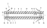
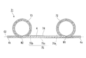
- the stent 1 of the present embodiment includes a coil 3 formed by winding an element wire 2 around an axis C ⁇ b> 1, a substantially tubular shape, and the coil 3 is coaxial with the coil 3.
- An outer layer 4 provided on the outer peripheral side and an inner layer 5 formed in a substantially tubular shape and provided coaxially with the coil 3 on the inner peripheral side of the coil 3 are provided.
- the strand 2 is made of a metal such as tungsten steel or stainless steel, which is a radiopaque material, and has a circular cross section. In the present embodiment, for example, a strand 2 having an outer diameter of 0.11 mm is used.
- the element wire 2 is spirally wound around the axis C1 to form a coil 3.
- the strand 2 has a pitch P1 of about 0.41 mm in this embodiment (the gap between the strands 2 is 0). About 30 mm).
- the outer layer 4 is formed of a polyurethane elastomer resin (first resin material) having a Shore hardness of 70D or less and a glass transition temperature higher than ⁇ 40 ° C., and an outer diameter nominal dimension K of 10 French (3.2 mm, or less). "French” is described as “Fr”).
- the outer layer 4 is provided not only on the outer peripheral surface of the coil 3 but also in the gap between the strands 2.
- the bending elastic modulus of the outer layer 4 is set to 700 MPa or less.
- the outer layer 4 was formed with the above-mentioned polyurethane-type elastomer resin, as a material which forms the outer layer 4, it is not restricted to this.
- a polyamide elastomer / polyethylene elastomer having a Shore hardness of 70D or less and a glass transition temperature higher than ⁇ 40 ° C. a soft polyethylene, a polystyrene elastomer, a polyester elastomer, or the like is appropriately used.
- the flexural modulus of the outer layer 4 is preferably 5 MPa or more
- the Shore hardness of the polyurethane elastomer, polyamide elastomer, soft polyethylene, polystyrene elastomer, and polyester elastomer is preferably 25 D or more.
- biocompatibility property that fits in the body in bending, flexible and low elasticity
- stent invasion and deviation such as stent invasion and deviation, ulceration, etc.
- It is effective for suppression, pain reduction (low invasiveness), etc. to patients.
- the inner layer 5 is made of a material (second resin material) such as PFA (perfluoroalkoxylalkane), FEP, or PTFE, which is a fluororesin and has elasticity. Further, the flexural modulus of the inner layer 5 is desirably 1000 MPa or less.
- the distance from the outer peripheral surface of the outer layer 4 to the inner peripheral surface of the inner layer 5, that is, the thickness D1 of the stent 1 is set to be 0.20 mm or more and 0.35 mm or less in this embodiment. More specifically, the inner layer 5 has a wall thickness of 0.005 mm or more and 0.10 mm or less, and the outer layer 4 has a wall thickness of 0.07 mm or more and 0.34 mm or less. It is arbitrarily set according to the size of. Setting such a thickness is effective in reducing crushing resistance, flexibility, wide lumen, or outer diameter.
- flaps (locking members) 8 to 11 are provided at equal angles around the axis C 1 on the outer peripheral surface on the distal end portion 4 a side which is the distal end side when inserted into the bile duct. (Flap 11 is not shown).
- the flaps 8 to 11 are formed by cutting up a part of the front end portion 4a of the outer layer 4.
- the flaps 8 to 11 have elasticity. When the flaps 8 to 11 are pressed toward the radially inner side of the outer layer 4, the flaps 8 to 11 are notched portions 12 to 15 (the notch portion 15 is (Not shown).
- flaps 16 to 19 are provided at equal angles around the axis C1 (the flap 19 is not shown).
- the flaps 16 to 19 are formed by cutting and raising a part of the base end portion 4b of the outer layer 4.
- the lengths of the flaps 16 to 19 in the direction along the axis C1 are set shorter than the flaps 8 to 11.
- the flaps 16 to 19 have elasticity. When the flaps 16 to 19 are pressed toward the inner side in the radial direction of the outer layer 4, the flaps 16 to 19 are notched portions 20 to 23 (the notch portion 23 is (Not shown).
- the stent 1 When the stent 1 configured in this way is placed in the body, in order to maintain the size of the lumen regardless of the bending or running of the bile duct, the stent 1 is difficult to be crushed or broken. It is important to ensure kink) and biocompatibility (property that fits in a living body to bend, flexibility and low elasticity). In addition, it is important not to be crushed by stenosis after indwelling, or to bend and buckle (bend) because the bile duct itself is pulled by cancer infiltration. It is also important to ensure a sufficient lumen size. There is no established indicator that clearly shows the retention and flexibility of the lumen when the tubular stent is bent. Therefore, in the present invention, the following cantilever stiffness test was performed.
- the maximum bending load Y1 obtained by this cantilever stiffness test As shown in FIG. 3, the maximum bending load Y1 obtained by this cantilever stiffness test, the deflection X1 when the maximum bending load Y1 is applied, and the difference between the maximum bending load Y1 and the return bending load Y2 in the deflection X1.
- the elastic force Z and the thickness D1 of the stent are used as indexes indicating the degree of lumen retention, flexibility, and lumen width.
- index A the value obtained by dividing the maximum bending load Y1 by the deflection X1 at the maximum bending load was taken as index A.
- the percentage of the value obtained by dividing the resilience Z by the index A was used as the index B. That is, the resilience Z, the index A, and the index B can be expressed by equations (2) to (4).
- the index A, the index B, and the wall thickness D1 are appropriately set.
- setting each index appropriately sets the thickness of the inner layer 5 to 0.005 mm or more and 0.10 mm or less, and sets the thickness of the outer layer 4 to 0.07 mm or more and 0.34 mm or less. Is achieved.
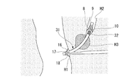
- FIG. 4 is a diagram for explaining a method of a cantilever stiffness test in the present invention.
- the stent S1 that is symmetrical to the measurement may or may not have a flap.
- a cylindrical core R1 having a diameter substantially the same as the lumen is inserted into the lumen of the stent S1.
- the range in which the core body R1 is inserted is from the proximal end side of the stent S1 to the position S2 of 10 mm from the distal end of the stent S1.
- the stent S1 is horizontally disposed, and the outer peripheral surface of the stent S1 corresponding to the range into which the core body R1 is inserted is sandwiched and supported by the clamp R2.
- the attachment R3 is set so that the center of the attachment R3 comes into contact with the outer peripheral surface of the stent S1 from above at a position S3 that is 5 mm away from the position S2 toward the distal end. Then, while measuring in parallel the deflection X when the attachment R3 is pushed down and the reaction force (bending load Y) that the attachment R3 receives from the stent S1 by the measurement device (not shown), the attachment R3 is 5 mm per minute. Push down 5mm vertically at speed. Further, after the attachment R3 is pushed down by 5 mm, the attachment R3 is returned in the reverse direction at the same speed, and the force received from the stent S1 is measured.
- the shape of the attachment R3 is formed in a plate shape having a width of 20 mm and a thickness of 5 mm, as shown in FIG.
- the contact surface R4 of the attachment R3 with respect to the stent S1 is formed in a curved surface with a radius of curvature of 2.5 mm so that the bending load on the stent S1 is not concentrated on one point.
- FIG. 6 shows an example of the results of a cantilever stiffness test performed on the stent 1 of the present embodiment.
- the vertical axis in FIG. 6 indicates the bending load Y
- the horizontal axis indicates the deflection X.
- the deflection X of the stent 1 increases, and the stent 1 takes the maximum bending load Y1 at a certain deflection X1. Thereafter, even if the deflection X is increased, the bending load Y decreases.
- the stent 1 bends while following, but when the maximum bending load Y1 is larger than a predetermined value and a special member such as a reinforcing layer for holding the lumen is not provided, the stent is bent. If the maximum bending load Y1 is small, the stent is easy to bend, and if the maximum bending load Y1 is large, the stent is difficult to bend (low flexibility). However, when the maximum bending load Y1 is small and the deflection X1 when the maximum bending load Y1 is shown is smaller than a certain value, the stent is bent (kinked) while bending until the deflection X becomes 5 mm. This indicates that the cavity cannot be retained.
- the difference between the maximum bending load Y1 and the return bending load at the deflection X1 when indicating the maximum bending load Y1 is small, it indicates that the elastic force is large, that is, the force to return to the original shape is large. Yes.
- the index A is greater than a certain value, it is difficult to bend (hard), and the lumen retention during bending is weak.
- the index A is smaller than a certain value, it is easy to bend (flexible), but the lumen retention during bending is weak.
- the thickness D1 is larger than a certain value, it indicates that the inner diameter is small in a certain nominal dimension.
- the thickness D1 is smaller than a certain value, it indicates that the inner diameter is large in a certain nominal dimension.
- the index B when the index B is large, it indicates that the elastic force is large, and when the index B is small, it indicates that plastic deformation is easy.
- a small index B is preferable as a stent, but if the treatment is taken into consideration, the operability is lowered. That is, the matter required for the stent is that the index A, the index B, and the wall thickness D1 show appropriate values.
- the upper limit value of the maximum bending load Y1 required for the stent, the lower limit value of the deflection X1 at the maximum bending load Y1, and the return bending load Y2 are the nominal dimension K of the outer diameter of the stent. It depends on (see Fig. 1).
- the stent 1 of this embodiment has a nominal dimension K of 10 Fr, an inner diameter of ⁇ 2.8 mm, and an outer diameter of ⁇ 3.2 mm.
- the index A is smaller than 4 N / mm
- the thickness D1 is 0.20 mm or more and 0.35 mm or less
- the upper limit value of the index B is preferably 70%.
- the index A is 1.29 N / mm
- the wall thickness D1 is 0.24 mm
- the index B is 56%
- the stent 1 can enlarge the lumen. It was also found that the lumen can be sufficiently retained, flexible, and less elastic.
- the index A is 0.49 N / mm
- the index B is 0.24 mm
- the index C is 50%. It has been found that the stent 1 can enlarge the lumen and can sufficiently retain the lumen, is flexible, and has little elasticity.
- FIG. 7 shows an example of a result of a cantilever stiffness test performed on a conventional stent having a nominal size of 10 French but not using a coil. It was found that the stent was broken at a certain deflection X3 smaller than 2.0 mm, and the stent lumen was reduced when the stent was bent until the deflection X reached 5 mm.
- an example of a result of a cantilever stiffness test performed on a conventional stent using a reinforcing layer that is not a coil, for example, a blade is shown.
- the operation of the stent 1 configured as described above will be described as an example of a procedure for placing the stent 1 in the bile duct.
- the user inserts a side-view type endoscope into the patient's body cavity through a natural opening such as the mouth, and advances the tip of the endoscope E1 to the vicinity of the duodenal papilla H1 as shown in FIG.
- the user inserts a guide wire E2 from a forceps opening (not shown) of the endoscope E1, and causes the distal end of the guide wire E2 to protrude toward the duodenal papilla H1 while appropriately operating an elevator (not shown). .
- the distal end of the guide wire E2 is inserted from the duodenal papilla H1 into the bile duct H2. Further, the user confirms the shape of the narrowed portion H3 of the duodenal papilla H1 and the bile duct H2 under fluoroscopy, and the flaps 8-11 are free when the flaps 8-11, 16-19 are opened.
- the stent 1 is selected so that the length from the end to the free end of the flaps 16 to 19 exceeds the stenosis H3 of the bile duct H2 from the duodenal papilla H1.
- the user uses the stent delivery catheter (not shown) inserted from the forceps opening to move the stent 1 along the guide wire E2 (ie, the flap 8).
- 11) Insert into the bile duct H2 from the side.
- the flaps 8 to 11 are pressed toward the axis C1 by the constriction H3, and the flaps 8 to 11 are accommodated in the cutouts 12 to 15, respectively.
- the flaps 16 to 19 are also related to the duodenal papilla H1. Stop.
- the user takes out the endoscope E1 from the body cavity of the patient and finishes a series of procedures.
- the stent 1 of the present embodiment since the coil 3 is provided between the outer layer 4 and the inner layer 5, the stent 1 is hardly crushed in the radial direction, and the bending of the bile duct and the running change are made. Even when a bending load due to the above is applied, the size of the lumen can always be maintained. In addition, since the blade is not used, it is possible to prevent the strands 2 from overlapping each other and become thicker in the radial direction, and to prevent the stent 1 from becoming difficult to bend due to friction caused by the strands 2.
- the outer layer 4 is formed of a polyurethane elastomer resin having a flexural modulus of 700 MPa or less, a Shore hardness of 70 D or less, and a glass transition temperature higher than ⁇ 40 ° C., the outer layer 4 is prevented from being hardened, The stent 1 can be easily bent as a whole. Furthermore, since the outer layer 4 is heated to almost the body temperature in the body, the outer layer 4 can be made more flexible.
- the nominal dimension K of the outer diameter of the outer layer 4 is 10 Fr, the value obtained by dividing the maximum bending load in the cantilever stiffness test by the deflection at the maximum bending load is 0.3 N / mm or more, and the stent 1
- the dimension and material of each member of the stent 1 are set so that the thickness D1 is 0.35 mm or less. Therefore, the stent 1 can be thinned, that is, a wide lumen can be secured, and the stent 1 can be easily bent and hardly collapsed. Further, since the flaps 8 to 11 and 16 to 19 are provided, the stent 1 can be locked to the narrowed portion H3 of the bile duct H2, and the stent 1 can be prevented from getting in and out. Can do.
- the outer diameter (outer diameter of the outer layer 4) of the stent having an inner diameter (inner diameter of the inner layer 5) of 7.2 Fr (2.4 mm) is reduced to 10. It can be made as thin as 0 Fr (3.3 mm) to 8.5 Fr (2.8 mm). Also, the outer diameter of the stent having an inner diameter of 8.5 Fr (2.8 mm) is reduced from the conventional 11.5 to 12.0 Fr (3.8 to 4.0 mm) to 10.0 Fr (3.2 mm). can do.
- the stent 1 of the present embodiment it is possible to provide a stent having the same inner diameter and a thinner outer diameter as compared with a conventional stent, or a stent having the same outer diameter and a larger inner diameter. Can do.
- the coil 3 it is not necessary to use a large amount of contrast agent in the stent 1, so that the factor of deterioration in physical properties of the stent 1 can be reduced. Further, when the stent 1 is invaded or when a technique (inside stent) for intentionally inserting the proximal end 4b into the bile duct is used, the position of the proximal end 4b of the stent 1 is fluoroscopically viewed by the coil 3. It can be confirmed below, and the recovery of the stent 1 is facilitated.
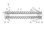
- the same parts as those in the first embodiment are denoted by the same reference numerals, description thereof is omitted, and only different points will be described.
- the wire 2 at a predetermined position on the axis C1 of the coil 3 is wound substantially densely around the axis C1.
- the coil 33 includes a marker coil portion 32 wound around the wire and normal winding coil portions 34 and 35 wound at the same pitch P1 as the wire 2 of the coil 3 of the first embodiment.
- substantially densely wound means that the strands are wound at a constant pitch that is greater than 1 times the outer diameter of the strands and not more than 7 times.
- the gap between adjacent strands 2 is 0.01 to 0.08 mm, and the pitch P2 of the strands 2 Becomes 0.12 to 0.19 mm.
- the pitch P2 of the strand 2 is about 1.1 to 1.7 times the outer diameter of the strand 2. For convenience of explanation, this gap is not shown in the drawing.
- the outer layer 4 and the inner layer 5 are connected to each other at the gap between the adjacent wires 2 in the marker coil portion 32, and the outer layer 4 and the inner layer 5 are hardly separated from each other. can do. Further, if the dimension of the marker coil part 32 deviates from the above, the difference in radiopacity between the coil pitch of the sparse part (ie, the normal winding coil part) and the coil pitch of the dense part (ie, the marker coil part). Can no longer be born. In addition, it is preferable that the length along the axis C1 of this marker coil part 32 is 9 mm or less. This is because the forceps riser at the exit of the endoscope passes smoothly.
- the degree of freedom of the coil is fixed within a certain range, when the length along the axis C1 of the marker coil portion 32 is 9 mm or more, the forceps elevator base passes when the forceps elevator base is up. It can be difficult.
- the tip end of the marker coil portion 32 is disposed so as to be at the same position as the base end of the notch portion 12 in the direction of the axis C1.
- the portions other than the marker coil portion 32 in the coil 33 are configured by normal winding coil portions 34 and 35 wound at the same pitch P1 (about 0.41 mm) as the element wire 2 of the coil 3 of the first embodiment. It is preferable that the pitch P1 of the strand 2 in the normal winding coil portions 34 and 35 is not less than 2 times and not more than 20 times the pitch P2 of the strand 2 of the marker coil portion 32. If the pitch P1 is less than twice the pitch P2, it is difficult to distinguish between the marker coil portion 32 and the normal winding coil portions 34 and 35 under fluoroscopy. If the pitch P1 is larger than 20 times the pitch P2, the size of the lumen cannot be maintained when the stent 31 is bent. Further, the resin does not enter the gap between the strands 2 wound at the pitch P2, and the portion swells up.
- the normal winding coil part 34 is connected to the tip of the marker coil part 32, and the normal winding coil part 35 is connected to the base end of the marker coil part 32.
- the marker coil portion 32, the normal winding coil portion 34, and the normal winding coil portion 35 constitute a coil 33.
- the X-ray opacity (X-ray shielding degree) of the marker coil portion 32, the normal winding coil portion 34, and the normal winding coil portion under X-ray fluoroscopy Since the X-ray opacity of 35 is so visible that the boundary between the marker coil portion 32 and the normal winding coil portion 34 and the boundary between the marker coil portion 32 and the normal winding coil portion 35 can be specified.
- the user inserts the stent 31 into the bile duct H2 while identifying the shape of the bile duct H2 and the position of the marker coil portion 32 of the coil 33 under fluoroscopy. Then, when the insertion of the stent 31 is stopped when the marker coil portion 32 exceeds the stenosis H3, the flaps 8 to 11 are spread and locked to the stenosis H3.
- flaps formed so as to open in a natural state are formed at the distal end portion and the proximal end portion, respectively.
- the flap formed at the distal end portion is pushed and closed by the stenosis portion.
- the flap passes through the narrowed portion of the bile duct, the closed flap is opened and the flap is locked to the bile duct, and the movement of the stent to the duodenum side is restricted.
- the stent 31 of the present embodiment As described above, according to the stent 31 of the present embodiment, as with the stent 1, while maintaining the ease of bending by suppressing the wall thickness, it is always possible even when a bending load is applied due to bending or running changes of the bile duct. It can be made difficult to be crushed. Further, the pitch at which the wire 2 is wound is different between the marker coil portion 32 and the normal winding coil portions 34 and 35. For this reason, when the X-ray having a certain intensity is irradiated onto the coil 33, a difference occurs between the X-ray opacity of the marker coil portion 32 and the X-ray opacity of the normal winding coil portions 34 and 35. Due to this difference in strength, the positions of the tips (free ends) of the flaps 8 to 11 in the stent 31 can be visually recognized under fluoroscopy.
- the strength of the flap 8 can be increased. Thereby, the factor of the physical property fall of the flap 8 can be reduced. Since the marker coil part 32 is provided in the intermediate part of the stent 31 in the direction of the axis C1, the entire stent 31 can be confirmed more clearly. This is useful for placement from the second when placing a plurality of stents.
- the flaps 8 to 11 are pressed and locked against the inner wall of the narrowed portion H3, and the free end is on the outer peripheral surface side of the outer layer 4 Move to.
- the user can visually recognize the shape of the living bile duct H2 and the position of the marker coil portion 32 of the stent 31 under fluoroscopy.
- the X-ray marker positioned in the vicinity of the flaps 8 to 11 is the marker coil section 32, it can be flexibly bent even with respect to local bending.
- the user advances the flaps 8 to 11 into the constricted portion of the bile duct H2 by causing the marker coil portion 32 that can be specified under fluoroscopy to enter the bile duct H2 beyond the constricted portion H3 of the bile duct H2. It can be reliably locked to the back side of H3.
- the strand 2 is wound substantially densely around the axis C ⁇ b> 1 around both the distal end portion and the proximal end portion of the coil 33 in the same manner as the marker coil portion 32 described above.
- the marker coil part 42 and the marker coil part 43 may be provided.
- the marker coil 43 is strong against compression in the direction of the axis C1, and the strands are wound relatively densely compared to a sparse portion (normally wound coil portion) in which the strands are wound relatively sparsely. Since the dense portion (marker coil portion) has a small distance between the strands 2, it is considered that the resin is not sufficiently filled in the gap between the strands 2. The reason for the latter will be further described below. Compared to the sparse part, the dense part has a slightly larger outer diameter value. This means that the pipe cross-sectional area when transmitting the force from the base end 4b side to the tip end 4a side is large. Therefore, the stent 41 can be easily inserted by providing the marker coil portion 43 in which the wire is wound relatively densely on the base end portion 4b that is the side directly receiving the force.
- the stent 51 of the present embodiment includes a coil 53 instead of the coil 33 of the stent 41 of the modified example of the second embodiment.
- the coil 53 includes a normal winding coil portion 35, marker coil portions 42 and 43 provided at both ends of the coil 53, a coarse winding coil portion 54 provided between the normal winding coil portion 35 and the marker coil portion 42, A rough winding coil portion 55 provided between the normal winding coil portion 35 and the marker coil portion 43 is provided.
- the pitch P1 of the wire 2 in the normal winding coil portion 35 is not less than 2 times and not more than 20 times the pitch P2 of the wire 2 of the marker coil portions 42 and 43, and the coarse winding coil portions 54 and 55. It is preferable that the pitch P3 of the strand 2 is 1.1 to 5 times the pitch P1 of the strand 2 of the normal winding coil portion 35. Since the pitch of the wire 2 of each of the coarse winding coil portions 54 and 55 is 1.1 times or more than the pitch of the wire 2 of the normal winding coil portion 35, the boundary between the coarse winding coil portion 54 and the normal winding coil portion 35 is present.
- the boundary between the coarsely wound coil part 55 and the normal wound coil part 35 can be visually recognized under X-ray fluoroscopy.
- the pitch of the strand 2 of the coarsely wound coil portion 54 is twice or more the pitch of the strand 2 of the marker coil portion 42
- the pitch of the strand 2 of the coarsely wound coil portion 55 is the strand of the marker coil portion 43. Since the pitch is equal to or larger than twice the pitch of 2, the coarsely wound coil portion 54 and the marker coil portion 42 and the boundary, and the coarsely wound coil portion 55 and the marker coil portion 43 and the boundary can also be visually recognized under X-ray fluoroscopy.
- the coarsely wound coil portion 54 and the coarsely wound coil portion 55 are provided in ranges substantially corresponding to the flaps 8 to 11 and the flaps 16 to 19 in the direction along the axis C1.
- the stent 51 of the present embodiment configured as described above, like the stent of each of the embodiments, it is possible to suppress the thickness and maintain easiness of bending while making it difficult to be crushed. Further, the positions corresponding to the fixed ends and the free ends of the flaps 8 to 11 and the flaps 16 to 19 can be specified by visually recognizing the boundary between adjacent coils under fluoroscopy.
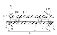
- the stent 61 of the present embodiment is shifted in position on the axis C1 to be a marker coil (coil) 64, a normal coil (coil). 65, a marker coil (coil) 66 is provided.
- the marker coils 64 and 66 are formed by winding the wire 2 in a substantially dense winding around the axis C1 at the same pitch P2 as the marker coil portion 32 described above.
- the normal winding coil 65 is formed by winding the wire 2 around the axis C1 at the same pitch P1 as the normal winding coil portion 35 described above.
- the normal winding coil 65 and the marker coil 64 are respectively connected by a connecting portion 67, and the normal winding coil 65 and the marker coil 66 are respectively connected by a connecting portion 68.
- the connecting portion 67 is formed by a set of strands 2 parallel to the axis C ⁇ b> 1.
- the element wires 2 are arranged so as to be symmetrical with respect to the axis C 1, and one end of each element wire 2 is connected to the marker coil 64 and the other end is connected to the normal winding coil 65.
- various known methods such as soldering, spot welding, or connection using a T-shaped joint member can be used.
- the number and position of the strand 2 used for the connection part 67 can be set suitably.
- the connection portion 68 is formed of a pair of strands 2 as with the connection portion 67, and one end of each strand 2 is connected to the marker coil 66 and the other end is connected to the normal winding coil 65.
- the stent 61 of the present embodiment configured as described above, it is possible to suppress the wall thickness and maintain easiness of bending, and to make it always difficult to be crushed even when a bending load due to bending or running change of the bile duct is applied. Furthermore, since the strands 2 of the connecting portions 67 and 68 are arranged so as to extend along the axis C1, the force acting in the direction of the axis C1 at the distal end 4a is applied to the proximal end 4b and at the proximal end 4b. A force acting in the direction of the axis C1 can be efficiently transmitted to the tip portion 4a.
- the stent 61 By transmitting the force in this way, when the stent 61 is placed in the bile duct H2 with a known stent pusher, the force received by the proximal end portion 4b of the stent 61 by the stent pusher is transmitted to the distal end portion 4a, and the stent 61 is It can be inserted into the constriction H3 of the bile duct H2 more easily.
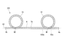
- the stent 71 of the present embodiment is not provided with a flap, and is so-called rotated so as to form a loop surface parallel to the axis C2 at the distal end portion 4a and the proximal end portion 4b.
- Each has bent portions 72 and 73 formed in a pigtail shape.
- a portion of the stent 71 sandwiched between the bent portion 72 and the bent portion 73, that is, a portion adjacent to each of the bent portion 72 and the bent portion 73 is a main body portion 74.
- a coil 75 described later is provided in the outer layer 4, and the above-described inner layer 5 (not shown) is further provided in the coil 75.
- the strand 2 is connected to the distal end 4a side from the boundary M1 between the bent portion 72 and the main body portion 74 and from the boundary M2 between the bent portion 73 and the main body portion 74 to the proximal end portion 4b side.
- a marker coil portion 75a and a marker coil portion 75b wound substantially densely around the axis C2 at the same pitch P2 as the marker coil portion 32 are formed.
- the normal winding coil part 75c by which the strand 2 was wound around the axis line C2 by the same pitch P1 as the above-mentioned normal winding coil part 35 is formed in the part pinched by the marker coil parts 75a and 75b. Yes.
- the positions of the boundaries M1 and M2 and the positions of the distal end portion 4a and the proximal end portion 4b can be specified under fluoroscopy. Further, the boundary can be specified also in appearance by the shade of hue caused by different coil pitches.
- the stent 81 of FIG. 18 replaces with the marker coil part 75a and the marker coil part 75b of the stent 71 of the said embodiment, and the strand 2 is the axis C2 with the same pitch P1 as the above-mentioned normal winding coil part 35.
- the normal winding coil portion 82a and the normal winding coil portion 82b wound around are replaced with the normal winding coil portion 75c and the wire 2 is substantially densely wound around the axis C2 at the same pitch P2 as the marker coil portion 32 described above. Marker coil portions 82c wound around each may be provided.
- the wire 2 is placed only at a predetermined distance from the boundary M1 and at a predetermined distance from the distal end portion 4a.
- Marker coil portions 92a and 92b wound approximately densely around the axis C2 at the same pitch P2 as the portion 32 are provided, and the strand 2 is between the marker coil portions 92a and 92b in the same manner as the normal winding coil portion 35 described above.
- a normal winding coil portion 92c wound around the axis C2 at the pitch P1 may be provided.
- the proximal end portion 4b side of the stent 91 may be configured similarly to the distal end portion 4a side.
- the strand 2 has the same pitch P3 as that of the coarse winding coil portion 54 described above.
- a coarsely wound coil portion 102a wound around the axis C2 may be provided.
- the proximal end portion 4b side of the stent 101 may be configured similarly to the distal end portion 4a side.
- the wire 2 made of metal and having a circular cross section is used.
- a rectangular wire may be used as a strand, and this may be wound spirally to form a flat wire coil.
- the coil 3 is composed of the single-strand strand 2, but a so-called multi-strand winding in which a plurality of strands are aligned in the radial direction and wound spirally. You may comprise a coil with a strand.
- the strand 2 was wound by substantially dense winding, and the marker coil was formed.
- the wire 2 may be wound in a tight winding without providing a gap between the wire 2 of the marker coil.
- the pitch at which the wire 2 is wound is changed in order to visually recognize the position of the connecting portion of the adjacent coil.
- the diameter of the wire may be changed.
- the medical stent of the present invention it is possible to prevent the lumen from being crushed when bent while maintaining the characteristic of being easily bent and less elastic.
- contrast properties can be improved without reducing the physical properties of the stent such as flexibility and elasticity.
Abstract
A medical stent is provided with a coil which is formed by winding an element wire about an axis, an outer layer which is formed in a substantially tubular shape using a first resin material and which is provided on the outer peripheral side of the coil so as to be coaxial therewith, and an inner layer which is formed in a substantially tubular shape using a second resin material different from the first resin material and which is provided on the inner peripheral side of the coil so as to be coaxial therewith.
Description
本発明は、医療用ステントに関する。
本願は、2010年3月26日に、日本に出願された特願2010-073817号に基づき優先権を主張し、その内容をここに援用する。 The present invention relates to a medical stent.
This application claims priority based on Japanese Patent Application No. 2010-073817 filed in Japan on March 26, 2010, the contents of which are incorporated herein by reference.
本願は、2010年3月26日に、日本に出願された特願2010-073817号に基づき優先権を主張し、その内容をここに援用する。 The present invention relates to a medical stent.
This application claims priority based on Japanese Patent Application No. 2010-073817 filed in Japan on March 26, 2010, the contents of which are incorporated herein by reference.
従来、血管、消化管、胆管、膵管、尿管等の生体内管腔に形成された狭窄部に対して、この狭窄部を拡張し、開存状態を維持するために、医療用ステント(以下、「ステント」とも称する。)の留置が行われている。
特許文献1に示すような胆管用に用いられるステントは、略管状に形成されていて、その先端側と基端側には、自然状態で開いており、所定の外力を加えると閉じるように変形可能なフラップがそれぞれ設けられている。これらのフラップを十二指腸乳頭の入口と胆管の狭窄部の端部にそれぞれ係止することにより、狭窄部に対するステントの移動が防止される。 Conventionally, in order to expand this stenosis part and maintain the patency state with respect to the stenosis part formed in the body lumen such as blood vessel, digestive tract, bile duct, pancreatic duct, ureter, etc. , Also referred to as “stent”).
A stent used for a bile duct as shown inPatent Document 1 is formed in a substantially tubular shape, and its distal end side and proximal end side are opened in a natural state and deformed to close when a predetermined external force is applied. Each possible flap is provided. By locking these flaps to the entrance of the duodenal papilla and the end of the stenosis of the bile duct, movement of the stent relative to the stenosis is prevented.
特許文献1に示すような胆管用に用いられるステントは、略管状に形成されていて、その先端側と基端側には、自然状態で開いており、所定の外力を加えると閉じるように変形可能なフラップがそれぞれ設けられている。これらのフラップを十二指腸乳頭の入口と胆管の狭窄部の端部にそれぞれ係止することにより、狭窄部に対するステントの移動が防止される。 Conventionally, in order to expand this stenosis part and maintain the patency state with respect to the stenosis part formed in the body lumen such as blood vessel, digestive tract, bile duct, pancreatic duct, ureter, etc. , Also referred to as “stent”).
A stent used for a bile duct as shown in
この種のステントには、生体内の胆管の屈曲形状や生体の動きに追従するための曲げ易さ、すなわち柔軟性と、ステントが曲げられたとき潰れずに自身の内腔の大きさを保持する硬さ(内腔保持性)という、相反するような特性が求められる。
ステントが生体内で曲げられたときに内腔が潰れ、内腔が狭くなることで胆汁等が通過し難くなるのは大きな問題である。ステントの閉塞の原因は未だに明確には解明されていないが、一般的に、内腔が広いステントの方が内腔が狭いステントに比べて閉塞し難い。 This type of stent retains the bending shape of the bile duct in the living body and the ease of bending to follow the movement of the living body, that is, flexibility and the size of its own lumen without collapsing when the stent is bent. The contradictory property of hardness (lumen retention) is required.
When the stent is bent in the living body, the lumen is crushed and the lumen is narrowed, so that it is difficult to pass bile or the like. Although the cause of the occlusion of the stent has not yet been clearly clarified, in general, a stent having a wide lumen is less likely to be occluded than a stent having a narrow lumen.
ステントの1つの構成として、軟性の樹脂(例えば、軟質ポリエチレン、ポリスチレン系エラストマー、ポリアミド系エラストマー、ポリエステル系エラストマー、ポリウレタン系エラストマー等)を管状に形成したものがある。この場合、ステントの曲げ易さを向上させることができるが、ステントが径方向に潰れるのを防止するためにステントの肉厚を厚く設定する必要がある。ステントの肉厚が薄いと、ステントとして最低限必要な内腔保持性を担保出来ないばかりか、体内留置後に狭窄部に押しつぶされたり、癌の浸潤により胆管が引張られたりしてステントが屈曲する可能性がある。結果として、ステントは坐屈、又は潰れてしまい内腔保持が出来ない、つまり、ステントの重要な役割である胆汁の排出ができない可能性がある。よって、ステントには、少なくとも既存製品と同等程度の内腔保持性が要求されるが、内腔保持を優先させてステント肉厚を設定すると、肉厚が厚くなり柔軟性に富んだステントが得られない。
One configuration of a stent is one in which a soft resin (for example, soft polyethylene, polystyrene elastomer, polyamide elastomer, polyester elastomer, polyurethane elastomer, etc.) is formed in a tubular shape. In this case, the bendability of the stent can be improved, but it is necessary to set the thickness of the stent thick in order to prevent the stent from collapsing in the radial direction. If the stent is thin, not only the minimum lumen retention required as a stent cannot be guaranteed, but the stent bends due to crushing into the stenosis after indwelling or the bile duct being pulled due to cancer invasion. there is a possibility. As a result, the stent may buckle or collapse and cannot retain the lumen, i.e., it may not be able to drain bile, an important role of the stent. Therefore, stents are required to have lumen retention that is at least equivalent to that of existing products. However, if stent thickness is set with priority given to lumen retention, the stent will be thick and flexible. I can't.
また、ステントの肉厚を厚くした場合、外径(呼称寸法)が一定のときにはステントの内径が小さくなる。結果として、ステントの柔軟性が損なわれてしまう。さらには、ステントの肉厚を厚くすることで、ステントの弾発性(曲げたステントが真っ直ぐに戻ろうとする力)が大きくなり、生体内の胆管の屈曲形状に抵抗する力が発生する。この抵抗力は、ときにステントが留置された場所から移動する力となって現れ、ステントが胆管内の深部(肝臓側)に移動(迷入)したり、十二指腸側に脱落(逸脱)したりする可能性がある。この場合、新たな追加処置が必要となるため、患者への負担となる。
また、この抵抗力は、ときに屈曲した胆管を真っ直ぐに引き伸ばそうとする力となって現れ、胆管に不必要な負荷を与える可能性がある。特にステントの両端部においては、胆管上皮組織や十二指腸粘膜にステントが必要以上に押し付けられることで、潰瘍が形成される可能性がある。また、ステント両端部の内腔開口部が組織や粘膜に当接してしまうと、胆汁が流入・流出する経路が塞がれてしまうため、胆汁が通過できなくなる可能性がある。この場合、ステント本来の機能を発揮できなくなる。
また、外径(呼称寸法)が一定の場合に、ステントの肉厚を厚くするとステントの内腔が小さくなるという問題は、ステントの開存期間(ステントが閉塞するまでの期間)に影響を及ぼす。よって、内腔保持性、柔軟性に富み、より大きい内腔のステントが望まれる。 Further, when the thickness of the stent is increased, the inner diameter of the stent is reduced when the outer diameter (nominal dimension) is constant. As a result, the flexibility of the stent is impaired. Furthermore, by increasing the thickness of the stent, the elasticity of the stent (the force that the bent stent tries to return straight) increases, and a force that resists the bent shape of the bile duct in vivo is generated. This resistance force sometimes appears as a force that moves from where the stent is placed, and the stent moves (invades) deep into the bile duct (liver side) or falls off (deviates) to the duodenum side. there is a possibility. In this case, a new additional treatment is required, which is a burden on the patient.
In addition, this resistance force sometimes appears as a force to stretch the bent bile duct straight, and may give an unnecessary load to the bile duct. In particular, at both ends of the stent, there is a possibility that an ulcer may be formed by pressing the stent more than necessary against the bile duct epithelial tissue or the duodenal mucosa. Also, if the lumen openings at both ends of the stent come into contact with the tissue or mucous membrane, the path through which bile flows in / out is blocked, and bile may not pass through. In this case, the original function of the stent cannot be exhibited.
In addition, when the outer diameter (nominal dimension) is constant, the problem that the stent lumen becomes smaller when the stent thickness is increased affects the stent patency period (the period until the stent is occluded). . Therefore, there is a demand for a stent having a larger lumen, which is rich in lumen retention and flexibility.
また、ステントの他の構成として、軟性の樹脂に金属製の素線を網状に編んだブレードを内蔵させたものがある。この場合、ステントを曲げたときに、ブレードの剛性により内腔の大きさを保持することができる。しかしながら、硬質のブレードを樹脂内に内蔵させることで、結果としてステントの柔軟性が損なわれ、弾発性が大きくなってしまう。また、ブレードにおける素線と素線が重なる部分では、径方向に厚くなり、素線同士の摩擦によりステントが曲げ難くなってしまう。すなわち、素線と素線が重なる部分では、柔軟性が低下し、弾発性が大きくなってしまう。
Also, as another configuration of the stent, there is one in which a blade made by knitting a metal wire into a net is built in a soft resin. In this case, when the stent is bent, the lumen size can be maintained by the rigidity of the blade. However, by incorporating a hard blade in the resin, as a result, the flexibility of the stent is impaired and the elasticity becomes large. Further, the portion where the strands of the blade overlap each other becomes thicker in the radial direction, and the stent becomes difficult to bend due to friction between the strands. That is, in a portion where the strands overlap, the flexibility is lowered and the elasticity is increased.
また、ステントには、X線透視下での視認性が必要とされる。ステントを留置する際やステント留置後に、X線を照射することによりステントの位置を確認する必要があるためである。胆汁が確実に通過するためには、ステントの両端部が狭窄部をまたいでいることが重要である。なお、留置後のステントの移動(迷入・逸脱)を防止するためには、ステントの先端側のフラップが確実に狭窄部を超えていることが重要である。すなわち、狭窄上部で明確にプラップが開放され、狭窄部にステントが係止されていることを確認する必要がある。なお、ステントが胆管内に迷入してしまった場合には、X線視認下でステントの位置を確認しながら、ステントの抜去をおこなう必要がある。把持鉗子などでステントの基端部を把持することで、ステントの抜去、回収を行う。従って、ステントの抜去の際には、X線透視下でステント全体が見えることに加えて、ステント基端部が明確に確認できることが必要である。ステント基端部が明確に視認できない場合には、ステントの把持に時間を要することがあり、手技時間の延長による患者への負担や術者のストレスにつながっていた。
Also, the visibility of the stent under X-ray fluoroscopy is required. This is because it is necessary to confirm the position of the stent by irradiating X-rays when placing the stent or after placing the stent. In order to ensure the passage of bile, it is important that both ends of the stent straddle the stenosis. In order to prevent the movement (entrance / departure) of the stent after placement, it is important that the flap on the distal end side of the stent surely exceeds the stenosis. That is, it is necessary to confirm that the flap is clearly opened at the upper part of the stenosis and the stent is locked to the stenosis part. When the stent has entered the bile duct, it is necessary to remove the stent while confirming the position of the stent under X-ray viewing. By grasping the proximal end portion of the stent with grasping forceps or the like, the stent is removed and collected. Therefore, when the stent is removed, it is necessary to clearly confirm the proximal end portion of the stent in addition to being able to see the entire stent under fluoroscopy. If the proximal end of the stent is not clearly visible, it may take time to grasp the stent, leading to a burden on the patient and an operator's stress due to an extended procedure time.
また、ステント留置では、ステントを複数本留置することがある。その際、1本目に留置したステントの位置を知ることは手技上重要となる。全体的にステントが見える又は、両端部以外の一部分が見えることが望ましい。これは、2本目以降の手技において、1本目のステントが移動しているか否かを確認するためである。これまでのステントでは、上記の機能が無く、X線透視下画面とスコープ画面の両方を見ながらの手技であった。これは、術者及び介助者のストレスに繋がっていた。
In stent placement, multiple stents may be placed. At that time, it is important for the procedure to know the position of the stent placed in the first. It is desirable that the stent is visible as a whole or a part other than both ends is visible. This is for checking whether or not the first stent is moving in the second and subsequent procedures. Conventional stents do not have the above-described functions, and are procedures while viewing both the X-ray fluoroscopic screen and the scope screen. This led to stress on the surgeon and caregivers.
このような問題を解決するために、従来のステントの多くは、X線不透過物質である造影剤を樹脂に混練し、造影性を持たせていた。しかしながら、造影剤の添加量を増加することは、ステントとなる管の初期の物性(引張強度、柔軟性、弾発性等)や長期的な物性を低下させる。また、体内に長期間留置されると、材料劣化を誘発する可能性がある。
造影性能を上げるために管の肉厚を上げると、結果として内腔が狭くなったり、外径が太くなったりする。また、柔軟性が損なわれたり、弾発性が大きくなったりする可能性がある。 In order to solve such a problem, many of the conventional stents have kneaded a contrast agent, which is a radiopaque material, in a resin so as to have contrast properties. However, increasing the amount of contrast medium added decreases the initial physical properties (tensile strength, flexibility, elasticity, etc.) and long-term physical properties of the stent tube. In addition, if left in the body for a long time, there is a possibility of inducing material deterioration.
Increasing the thickness of the tube to improve the contrast performance results in a narrower lumen and a thicker outer diameter. In addition, flexibility may be impaired, and elasticity may be increased.
特許文献2では、略円筒状に丸めた板状部材や環状部材を用いて部分的にX線視認性を上げる方法が提案されている。しかしながら、略円形状に丸めた板状部材や環状部材は少なくとも、屈曲の際、ある長さで直線状となり、任意の箇所で且つ任意の形状に曲げることが出来ない。これは結果としてステントの柔軟性を低下させ、弾発性を大きくし、製品性能を大きく低下させることとなる。
特許文献3では、内層材料と補強層と外層材料からなる医療用ステントが提案され、外層のみから成るフラップが示されている。しかしながら、フラップの肉厚は薄いため、造影剤が樹脂に混練してあってもX線視認性はあまり期待できず、フラップ近傍を確認することは困難となる。Patent Document 2 proposes a method of partially improving X-ray visibility using a plate-like member or an annular member rounded into a substantially cylindrical shape. However, a plate-like member or an annular member rounded into a substantially circular shape is linear at a certain length at the time of bending, and cannot be bent into an arbitrary shape at an arbitrary position. This results in reduced stent flexibility, increased resilience, and greatly reduced product performance.
Patent Document 3 proposes a medical stent composed of an inner layer material, a reinforcing layer, and an outer layer material, and shows a flap composed of only the outer layer. However, since the flap is thin, X-ray visibility cannot be expected so much even if the contrast medium is kneaded with the resin, and it is difficult to confirm the vicinity of the flap.
特許文献3では、内層材料と補強層と外層材料からなる医療用ステントが提案され、外層のみから成るフラップが示されている。しかしながら、フラップの肉厚は薄いため、造影剤が樹脂に混練してあってもX線視認性はあまり期待できず、フラップ近傍を確認することは困難となる。
本発明は、このような問題点に鑑みてなされたものであって、曲がり易く(柔軟性があり)、弾発性が少ないという特性を維持しつつも、曲げたときに内腔が潰れ難い医療用ステントを提供することを目的とする。また、ステントの柔軟性や弾発性などを低下させることなく、ステントの重要な機能の一つである造影性を向上させた医療用ステントを提供することを目的とする。
The present invention has been made in view of such problems, and it is easy to bend (there is flexibility) and maintains the characteristics of low elasticity, and the lumen is not easily collapsed when bent. An object is to provide a medical stent. It is another object of the present invention to provide a medical stent having improved contrast, which is one of the important functions of the stent, without reducing the flexibility and elasticity of the stent.
上記課題を解決するために、この発明は以下の手段を提案している。
本発明の医療用ステントは、素線を軸線回りに巻回させて形成したコイルと、第一の樹脂材料で略管状に形成され、前記コイルと同軸に前記コイルの外周側に設けられた外部層と、第二の樹脂材料で略管状に形成され、前記コイルと同軸に前記コイルの内周側に設けられた内部層と、を備える。 In order to solve the above problems, the present invention proposes the following means.
The medical stent of the present invention is formed in a substantially tubular shape with a coil formed by winding an element wire around an axis and a first resin material, and is provided on the outer peripheral side of the coil coaxially with the coil. A layer, and an inner layer formed on the inner peripheral side of the coil coaxially with the coil.
また、上記の医療用ステントにおいて、前記外部層の前記第一樹脂は、ポリアミドエラストマー樹脂、ポリエチレンエラストマー樹脂、ポリエチレン樹脂、ポリスチレンエラストマー又はポリウレタンエラストマー樹脂のいずれかであり、前記外部層において、ショア硬度が25D以上70D以下であり、ガラス転移温度が-40℃より高いことがより好ましい。
In the medical stent, the first resin of the outer layer is any one of a polyamide elastomer resin, a polyethylene elastomer resin, a polyethylene resin, a polystyrene elastomer, or a polyurethane elastomer resin, and the outer layer has a Shore hardness. More preferably, it is 25D or more and 70D or less and the glass transition temperature is higher than −40 ° C.
また、上記の医療用ステントにおいて、前記外部層の曲げ弾性率が5MPa以上700MPa以下であり、前記内部層の曲げ弾性率が1000MPa以下であることがより好ましい。
In the medical stent, it is more preferable that the bending elastic modulus of the outer layer is 5 MPa or more and 700 MPa or less, and the bending elastic modulus of the inner layer is 1000 MPa or less.
また、上記の医療用ステントにおいて、前記医療用ステントの肉厚が0.20mm以上0.35mm以下であり、片持ち剛性試験における最大曲げ荷重をY1(N)、前記最大曲げ荷重を作用させた時のたわみをX1(mm)とした時に、(1)式で規定される指標Aが4.0以下になるように構成されていることがより好ましい。
In the medical stent, the thickness of the medical stent is 0.20 mm or more and 0.35 mm or less, the maximum bending load in the cantilever stiffness test is Y1 (N), and the maximum bending load is applied. It is more preferable that the index A defined by the expression (1) is 4.0 or less when the deflection of time is X1 (mm).

また、上記の医療用ステントにおいて、前記素線はX線不透過性の材料で形成され、前記コイルは、前記素線を前記軸線方向に略密巻きに巻回させたマーカーコイル部と、前記マーカーコイル部に接続され、前記マーカーコイル部における前記素線の前記軸線方向のピッチに対して、2倍以上20倍以下のピッチで前記素線を前記軸線方向に巻回させた通常巻きコイル部と、を有することがより好ましい。
Further, in the above medical stent, the strand is formed of a radiopaque material, and the coil includes a marker coil portion in which the strand is wound substantially densely in the axial direction, and the coil A normal winding coil unit connected to a marker coil unit and wound in the axial direction at a pitch not less than 2 times and not more than 20 times the pitch in the axial direction of the strands in the marker coil unit And more preferably.
また、上記の医療用ステントにおいて、前記素線はX線不透過性の材料で形成され、前記コイルは、前記軸線上に位置をずらして複数備えられ、複数の前記コイルのうち隣り合うコイルは、前記軸線に平行な素線からなる接続部によりそれぞれ接続されていることがより好ましい。
Further, in the above medical stent, the strands are formed of a radiopaque material, and a plurality of the coils are provided with the positions shifted on the axis, and adjacent coils among the plurality of coils are More preferably, they are connected by connecting portions made of strands parallel to the axis.
また、上記の医療用ステントにおいて、第一の端が前記外部層の外周面に設けられ、かつ、第二の端が前記軸線に沿って延びつつ前記外部層の径方向外側に開くように形成された係止部材をさらに備え、前記コイルの前記マーカーコイル部は、前記軸線方向において前記係止部材の前記第二の端に対応する位置に設けられていることがより好ましい。
In the above medical stent, the first end is provided on the outer peripheral surface of the outer layer, and the second end extends along the axis and is opened radially outward of the outer layer. More preferably, the marker coil portion of the coil is further provided at a position corresponding to the second end of the locking member in the axial direction.
また、上記の医療用ステントにおいて、前記軸線方向において前記係止部材の前記第一の端に対応する位置には、前記マーカーコイル部がさらに設けられ、前記通常巻きコイルは、2つの前記マーカーコイル部にそれぞれ接続されていることがより好ましい。
In the medical stent, the marker coil portion may be further provided at a position corresponding to the first end of the locking member in the axial direction, and the normal winding coil may include two marker coils. It is more preferable that each is connected to each part.
また、上記の医療用ステントにおいて、少なくとも一方の端部に形成されたピッグテール状の曲がり部をさらに備え、前記コイルの前記マーカーコイル部は、前記曲がり部の端から所定の長さだけ延びるように設けられていることがより好ましい。
The medical stent may further include a pigtail-shaped bent portion formed on at least one end, and the marker coil portion of the coil may extend a predetermined length from the end of the bent portion. More preferably, it is provided.
本発明の医療用ステントによれば、曲がり易く弾発性が少ないという特性を維持しつつも、曲げたときに内腔を潰れ難くすることができる。また、柔軟性や弾発性など、ステントの物性を低下させることなく、造影性を向上させることができる。
According to the medical stent of the present invention, it is possible to prevent the lumen from being crushed when bent while maintaining the characteristic of being easily bent and less elastic. In addition, contrast properties can be improved without degrading the physical properties of the stent, such as flexibility and elasticity.
(第1実施形態)
以下、本発明に係るステントの第1実施形態を、図1から図9を参照しながら説明する。本実施形態のステントは、経内視鏡的に用いられるステントデリバリーカテーテル等により、生体の胆管内に留置される。なお、以下の全ての図面においては、図面を見やすくするため、各構成要素の厚さや寸法の比率は実際の寸法とは適宜異ならせてある。
図1及び図2に示すように、本実施形態のステント1は、素線2を軸線C1回りに巻回させて形成したコイル3と、略管状に形成され、コイル3と同軸にコイル3の外周側に設けられた外部層4と、略管状に形成され、コイル3と同軸にコイル3の内周側に設けられた内部層5を備えている。 (First embodiment)
Hereinafter, a first embodiment of a stent according to the present invention will be described with reference to FIGS. 1 to 9. The stent of this embodiment is placed in the bile duct of a living body by a stent delivery catheter or the like used for transendoscopy. In all of the following drawings, the thicknesses and dimensional ratios of each component are appropriately changed from the actual dimensions in order to make the drawings easy to see.
As shown in FIG. 1 and FIG. 2, thestent 1 of the present embodiment includes a coil 3 formed by winding an element wire 2 around an axis C <b> 1, a substantially tubular shape, and the coil 3 is coaxial with the coil 3. An outer layer 4 provided on the outer peripheral side and an inner layer 5 formed in a substantially tubular shape and provided coaxially with the coil 3 on the inner peripheral side of the coil 3 are provided.
以下、本発明に係るステントの第1実施形態を、図1から図9を参照しながら説明する。本実施形態のステントは、経内視鏡的に用いられるステントデリバリーカテーテル等により、生体の胆管内に留置される。なお、以下の全ての図面においては、図面を見やすくするため、各構成要素の厚さや寸法の比率は実際の寸法とは適宜異ならせてある。
図1及び図2に示すように、本実施形態のステント1は、素線2を軸線C1回りに巻回させて形成したコイル3と、略管状に形成され、コイル3と同軸にコイル3の外周側に設けられた外部層4と、略管状に形成され、コイル3と同軸にコイル3の内周側に設けられた内部層5を備えている。 (First embodiment)
Hereinafter, a first embodiment of a stent according to the present invention will be described with reference to FIGS. 1 to 9. The stent of this embodiment is placed in the bile duct of a living body by a stent delivery catheter or the like used for transendoscopy. In all of the following drawings, the thicknesses and dimensional ratios of each component are appropriately changed from the actual dimensions in order to make the drawings easy to see.
As shown in FIG. 1 and FIG. 2, the
素線2は、X線不透過性の材料であるタングステン鋼やステンレス鋼等の金属で形成され、その断面は円形に形成されている。本実施形態では、例えば、外径が0.11mmの素線2が用いられている。
素線2は軸線C1回りに螺旋状に巻回されてコイル3を形成している。軸線C1に沿う方向における隣り合う素線2の中心間の距離を素線2のピッチとすると、素線2は、本実施形態では0.41mm程度のピッチP1(素線2同士の隙間は0.30mm程度)で巻回されている。 Thestrand 2 is made of a metal such as tungsten steel or stainless steel, which is a radiopaque material, and has a circular cross section. In the present embodiment, for example, a strand 2 having an outer diameter of 0.11 mm is used.
Theelement wire 2 is spirally wound around the axis C1 to form a coil 3. When the distance between the centers of adjacent strands 2 in the direction along the axis C1 is the pitch of the strands 2, the strand 2 has a pitch P1 of about 0.41 mm in this embodiment (the gap between the strands 2 is 0). About 30 mm).
素線2は軸線C1回りに螺旋状に巻回されてコイル3を形成している。軸線C1に沿う方向における隣り合う素線2の中心間の距離を素線2のピッチとすると、素線2は、本実施形態では0.41mm程度のピッチP1(素線2同士の隙間は0.30mm程度)で巻回されている。 The
The
外部層4は、ショア硬度が70D以下、ガラス転移温度が-40℃より高いポリウレタン系エラストマー樹脂(第一の樹脂材料)で形成され、外径の呼称寸法Kが10フレンチ(3.2mm、以下では、「フレンチ」を「Fr」と記載する)となっている。外部層4は、コイル3の外周面だけでなく、素線2同士の隙間にも設けられている。
なお、外部層4の曲げ弾性率は、700MPa以下に設定されている。
また、本実施形態では、外部層4を上述のポリウレタン系エラストマー樹脂で形成したが、外部層4を形成する材料としてはこれに限られない。例えば、外層部4を形成する材料として、ショア硬度が70D以下で、ガラス転移温度が-40℃より高いポリアミド系エラストマー・ポリエチレン系エラストマー、軟質ポリエチレン、ポリスチレン系エラストマー、ポリエステル系エラストマー等を適宜用いることができる。
また、外部層4の曲げ弾性率は5MPa以上であることが好ましく、ポリウレタン系エラストマー、ポリアミド系エラストマー、軟質ポリエチレン、ポリスチレン系エラストマー、ポリエステル系エラストマーのショア硬度は、25D以上であることが好ましい。
このように、柔軟な材料を用いることで生体親和性(生体内で屈曲走行にフィットする性質、柔軟且つ低弾発性)を得ることができ、これはステントの迷入や逸脱、潰瘍形成等の抑制、患者への苦痛低減(低侵襲性)等に効果がある。 Theouter layer 4 is formed of a polyurethane elastomer resin (first resin material) having a Shore hardness of 70D or less and a glass transition temperature higher than −40 ° C., and an outer diameter nominal dimension K of 10 French (3.2 mm, or less). "French" is described as "Fr"). The outer layer 4 is provided not only on the outer peripheral surface of the coil 3 but also in the gap between the strands 2.
In addition, the bending elastic modulus of theouter layer 4 is set to 700 MPa or less.
Moreover, in this embodiment, although theouter layer 4 was formed with the above-mentioned polyurethane-type elastomer resin, as a material which forms the outer layer 4, it is not restricted to this. For example, as a material for forming the outer layer portion 4, a polyamide elastomer / polyethylene elastomer having a Shore hardness of 70D or less and a glass transition temperature higher than −40 ° C., a soft polyethylene, a polystyrene elastomer, a polyester elastomer, or the like is appropriately used. Can do.
Further, the flexural modulus of theouter layer 4 is preferably 5 MPa or more, and the Shore hardness of the polyurethane elastomer, polyamide elastomer, soft polyethylene, polystyrene elastomer, and polyester elastomer is preferably 25 D or more.
In this way, by using a flexible material, it is possible to obtain biocompatibility (property that fits in the body in bending, flexible and low elasticity), such as stent invasion and deviation, ulceration, etc. It is effective for suppression, pain reduction (low invasiveness), etc. to patients.
なお、外部層4の曲げ弾性率は、700MPa以下に設定されている。
また、本実施形態では、外部層4を上述のポリウレタン系エラストマー樹脂で形成したが、外部層4を形成する材料としてはこれに限られない。例えば、外層部4を形成する材料として、ショア硬度が70D以下で、ガラス転移温度が-40℃より高いポリアミド系エラストマー・ポリエチレン系エラストマー、軟質ポリエチレン、ポリスチレン系エラストマー、ポリエステル系エラストマー等を適宜用いることができる。
また、外部層4の曲げ弾性率は5MPa以上であることが好ましく、ポリウレタン系エラストマー、ポリアミド系エラストマー、軟質ポリエチレン、ポリスチレン系エラストマー、ポリエステル系エラストマーのショア硬度は、25D以上であることが好ましい。
このように、柔軟な材料を用いることで生体親和性(生体内で屈曲走行にフィットする性質、柔軟且つ低弾発性)を得ることができ、これはステントの迷入や逸脱、潰瘍形成等の抑制、患者への苦痛低減(低侵襲性)等に効果がある。 The
In addition, the bending elastic modulus of the
Moreover, in this embodiment, although the
Further, the flexural modulus of the
In this way, by using a flexible material, it is possible to obtain biocompatibility (property that fits in the body in bending, flexible and low elasticity), such as stent invasion and deviation, ulceration, etc. It is effective for suppression, pain reduction (low invasiveness), etc. to patients.
内部層5は、フッ素樹脂であり弾性を有するPFA(パーフルオロアルコキシルアルカン)、FEP、又はPTFE等の材料(第二の樹脂材料)で形成されている。また、内部層5の曲げ弾性率は1000MPa以下であることが望ましい。
外部層4の外周面から内部層5の内周面までの距離、すなわち、ステント1の肉厚D1は、本実施形態では0.20mm以上0.35mm以下になるように設定されている。
更に詳細には、内部層5の肉厚は0.005mm以上0.10mm以下であり、外部層4の肉厚は0.07mm以上0.34mm以下であり、柔軟性や弾発性、内腔の大きさ等にあわせて任意に設定する。
このような肉厚を設定することで耐潰れ性、柔軟性、広内腔又は外径の低減等に効果がある。 Theinner layer 5 is made of a material (second resin material) such as PFA (perfluoroalkoxylalkane), FEP, or PTFE, which is a fluororesin and has elasticity. Further, the flexural modulus of the inner layer 5 is desirably 1000 MPa or less.
The distance from the outer peripheral surface of theouter layer 4 to the inner peripheral surface of the inner layer 5, that is, the thickness D1 of the stent 1 is set to be 0.20 mm or more and 0.35 mm or less in this embodiment.
More specifically, theinner layer 5 has a wall thickness of 0.005 mm or more and 0.10 mm or less, and the outer layer 4 has a wall thickness of 0.07 mm or more and 0.34 mm or less. It is arbitrarily set according to the size of.
Setting such a thickness is effective in reducing crushing resistance, flexibility, wide lumen, or outer diameter.
外部層4の外周面から内部層5の内周面までの距離、すなわち、ステント1の肉厚D1は、本実施形態では0.20mm以上0.35mm以下になるように設定されている。
更に詳細には、内部層5の肉厚は0.005mm以上0.10mm以下であり、外部層4の肉厚は0.07mm以上0.34mm以下であり、柔軟性や弾発性、内腔の大きさ等にあわせて任意に設定する。
このような肉厚を設定することで耐潰れ性、柔軟性、広内腔又は外径の低減等に効果がある。 The
The distance from the outer peripheral surface of the
More specifically, the
Setting such a thickness is effective in reducing crushing resistance, flexibility, wide lumen, or outer diameter.
外部層4において、胆管内に挿入されるときに先端側となる先端部4a側の外周面には、軸線C1回りに等角度毎に4つのフラップ(係止部材)8~11が設けられている(フラップ11は不図示)。フラップ8~11は、外部層4の先端部4aの一部を切り起こすことにより形成されている。
フラップ8~11は弾性を有しており、フラップ8~11が外部層4の径方向内側に向けて押し付けられたときに、フラップ8~11が切り欠き部12~15(切り欠き部15は不図示)にそれぞれ収容される。 In theouter layer 4, four flaps (locking members) 8 to 11 are provided at equal angles around the axis C 1 on the outer peripheral surface on the distal end portion 4 a side which is the distal end side when inserted into the bile duct. (Flap 11 is not shown). The flaps 8 to 11 are formed by cutting up a part of the front end portion 4a of the outer layer 4.
Theflaps 8 to 11 have elasticity. When the flaps 8 to 11 are pressed toward the radially inner side of the outer layer 4, the flaps 8 to 11 are notched portions 12 to 15 (the notch portion 15 is (Not shown).
フラップ8~11は弾性を有しており、フラップ8~11が外部層4の径方向内側に向けて押し付けられたときに、フラップ8~11が切り欠き部12~15(切り欠き部15は不図示)にそれぞれ収容される。 In the
The
外部層4の基端部4bの外周面にも同様に、軸線C1回りに等角度毎に4つのフラップ16~19が設けられている(フラップ19は不図示)。フラップ16~19は、外部層4の基端部4bの一部を切り起こすことにより形成されている。フラップ16~19の軸線C1に沿う方向の長さはフラップ8~11より短く設定されている。
このように基端側(十二指腸側)のフラップを短くすることで、内視鏡出口の鉗子起上台での引っ掛かりによるトラブルを抑制することが出来る。
フラップ16~19の長さは、10mm以下であることが望ましい。フラップ16~19の長さが10mm以上になると、フラップが鉗子起上台を通過することが困難になり、ステントの挿入が困難になる。
フラップ16~19は弾性を有しており、フラップ16~19が外部層4の径方向内側に向けて押し付けられたときに、フラップ16~19が切り欠き部20~23(切り欠き部23は不図示)にそれぞれ収容される。 Similarly, on the outer peripheral surface of thebase end portion 4b of the outer layer 4, four flaps 16 to 19 are provided at equal angles around the axis C1 (the flap 19 is not shown). The flaps 16 to 19 are formed by cutting and raising a part of the base end portion 4b of the outer layer 4. The lengths of the flaps 16 to 19 in the direction along the axis C1 are set shorter than the flaps 8 to 11.
By shortening the flap on the proximal end side (duodenum side) in this way, it is possible to suppress troubles caused by catching on the forceps raising base at the endoscope exit.
The length of theflaps 16 to 19 is desirably 10 mm or less. When the lengths of the flaps 16 to 19 are 10 mm or more, it becomes difficult for the flaps to pass through the forceps raising base, and it becomes difficult to insert the stent.
Theflaps 16 to 19 have elasticity. When the flaps 16 to 19 are pressed toward the inner side in the radial direction of the outer layer 4, the flaps 16 to 19 are notched portions 20 to 23 (the notch portion 23 is (Not shown).
このように基端側(十二指腸側)のフラップを短くすることで、内視鏡出口の鉗子起上台での引っ掛かりによるトラブルを抑制することが出来る。
フラップ16~19の長さは、10mm以下であることが望ましい。フラップ16~19の長さが10mm以上になると、フラップが鉗子起上台を通過することが困難になり、ステントの挿入が困難になる。
フラップ16~19は弾性を有しており、フラップ16~19が外部層4の径方向内側に向けて押し付けられたときに、フラップ16~19が切り欠き部20~23(切り欠き部23は不図示)にそれぞれ収容される。 Similarly, on the outer peripheral surface of the
By shortening the flap on the proximal end side (duodenum side) in this way, it is possible to suppress troubles caused by catching on the forceps raising base at the endoscope exit.
The length of the
The
このように構成されたステント1が体内に留置された際に、胆管の屈曲や走行等にかかわらず内腔の大きさが保持されるためには、ステント1の潰れ難さや折れ難さ(耐キンク性)、生体親和性(生体内で屈曲走行にフィットする性質、柔軟且つ低弾発性)の確保が重要になる。また、体内留置後に狭窄に押しつぶされたり、癌の浸潤により胆管自体が引張られてステントが屈曲し、坐屈(折れる)したりしないことが重要となる。また、十分な内腔の広さを確保することも重要となる。
管状のステントを曲げたときの内腔の保持性と、柔軟性とを明確に示す、確立された指標はない。そこで、本発明においては、以下の片持ち剛性試験を行った。図3に示すように、この片持ち剛性試験によって得られる最大曲げ荷重Y1、最大曲げ荷重Y1を作用させた時のたわみX1、最大曲げ荷重Y1とたわみX1における戻り曲げ荷重Y2との差である弾発力Z、およびステントの肉厚D1を、内腔の保持性・柔軟性・内腔の広さの程度を示す指標とする。
上記試験から得られたデータのうち、最大曲げ荷重Y1を最大曲げ荷重時のたわみX1で除した値を指標Aとした。また、弾発力Zを指標Aで除した値の百分率を指標Bとした。
すなわち、弾発力Z、指標A、および指標Bは、(2)~(4)式で表すことができる。 When thestent 1 configured in this way is placed in the body, in order to maintain the size of the lumen regardless of the bending or running of the bile duct, the stent 1 is difficult to be crushed or broken. It is important to ensure kink) and biocompatibility (property that fits in a living body to bend, flexibility and low elasticity). In addition, it is important not to be crushed by stenosis after indwelling, or to bend and buckle (bend) because the bile duct itself is pulled by cancer infiltration. It is also important to ensure a sufficient lumen size.
There is no established indicator that clearly shows the retention and flexibility of the lumen when the tubular stent is bent. Therefore, in the present invention, the following cantilever stiffness test was performed. As shown in FIG. 3, the maximum bending load Y1 obtained by this cantilever stiffness test, the deflection X1 when the maximum bending load Y1 is applied, and the difference between the maximum bending load Y1 and the return bending load Y2 in the deflection X1. The elastic force Z and the thickness D1 of the stent are used as indexes indicating the degree of lumen retention, flexibility, and lumen width.
Of the data obtained from the above test, the value obtained by dividing the maximum bending load Y1 by the deflection X1 at the maximum bending load was taken as index A. The percentage of the value obtained by dividing the resilience Z by the index A was used as the index B.
That is, the resilience Z, the index A, and the index B can be expressed by equations (2) to (4).
管状のステントを曲げたときの内腔の保持性と、柔軟性とを明確に示す、確立された指標はない。そこで、本発明においては、以下の片持ち剛性試験を行った。図3に示すように、この片持ち剛性試験によって得られる最大曲げ荷重Y1、最大曲げ荷重Y1を作用させた時のたわみX1、最大曲げ荷重Y1とたわみX1における戻り曲げ荷重Y2との差である弾発力Z、およびステントの肉厚D1を、内腔の保持性・柔軟性・内腔の広さの程度を示す指標とする。
上記試験から得られたデータのうち、最大曲げ荷重Y1を最大曲げ荷重時のたわみX1で除した値を指標Aとした。また、弾発力Zを指標Aで除した値の百分率を指標Bとした。
すなわち、弾発力Z、指標A、および指標Bは、(2)~(4)式で表すことができる。 When the
There is no established indicator that clearly shows the retention and flexibility of the lumen when the tubular stent is bent. Therefore, in the present invention, the following cantilever stiffness test was performed. As shown in FIG. 3, the maximum bending load Y1 obtained by this cantilever stiffness test, the deflection X1 when the maximum bending load Y1 is applied, and the difference between the maximum bending load Y1 and the return bending load Y2 in the deflection X1. The elastic force Z and the thickness D1 of the stent are used as indexes indicating the degree of lumen retention, flexibility, and lumen width.
Of the data obtained from the above test, the value obtained by dividing the maximum bending load Y1 by the deflection X1 at the maximum bending load was taken as index A. The percentage of the value obtained by dividing the resilience Z by the index A was used as the index B.
That is, the resilience Z, the index A, and the index B can be expressed by equations (2) to (4).

本実施形態のステント1は、上記指標A、指標B、および肉厚D1が適切に設定されていることが好ましい。それぞれの指標を適切に設定するとは、たとえば、内部層5の肉厚を0.005mm以上0.10mm以下に設定するとともに、外部層4の肉厚を0.07mm以上0.34mm以下に設定することにより達成される。
In the stent 1 of the present embodiment, it is preferable that the index A, the index B, and the wall thickness D1 are appropriately set. For example, setting each index appropriately sets the thickness of the inner layer 5 to 0.005 mm or more and 0.10 mm or less, and sets the thickness of the outer layer 4 to 0.07 mm or more and 0.34 mm or less. Is achieved.
図4は、本発明における片持ち剛性試験の方法を説明する図である。なお、測定対称となるステントS1にフラップはあっても無くても良い。
ステントS1の内腔に、この内腔と略同一の径を有する円柱状の芯体R1を挿入する。芯体R1を挿入する範囲は、ステントS1の基端側から、ステントS1の先端から10mmの位置S2までである。そして、ステントS1を水平に配置し、芯体R1を挿入した範囲に対応する部分のステントS1の外周面をクランプR2で挟んで支持する。
次に、アタッチメントR3の中心が位置S2から先端側に5mm離間した位置S3においてステントS1の外周面に上方から当接するように、アタッチメントR3をセットする。そして、不図示の計測装置により、アタッチメントR3を押し下げたときのたわみXと、アタッチメントR3がステントS1から受ける反力(曲げ荷重Y)とを並行して計測しつつ、アタッチメントR3を毎分5mmの速度で鉛直下方に5mm押し下げる。また、アタッチメントR3を5mm押し下げたあと、同速度でアタッチメントR3を逆方向に戻し、ステントS1から受ける力を計測する。 FIG. 4 is a diagram for explaining a method of a cantilever stiffness test in the present invention. Note that the stent S1 that is symmetrical to the measurement may or may not have a flap.
A cylindrical core R1 having a diameter substantially the same as the lumen is inserted into the lumen of the stent S1. The range in which the core body R1 is inserted is from the proximal end side of the stent S1 to the position S2 of 10 mm from the distal end of the stent S1. Then, the stent S1 is horizontally disposed, and the outer peripheral surface of the stent S1 corresponding to the range into which the core body R1 is inserted is sandwiched and supported by the clamp R2.
Next, the attachment R3 is set so that the center of the attachment R3 comes into contact with the outer peripheral surface of the stent S1 from above at a position S3 that is 5 mm away from the position S2 toward the distal end. Then, while measuring in parallel the deflection X when the attachment R3 is pushed down and the reaction force (bending load Y) that the attachment R3 receives from the stent S1 by the measurement device (not shown), the attachment R3 is 5 mm per minute. Push down 5mm vertically at speed. Further, after the attachment R3 is pushed down by 5 mm, the attachment R3 is returned in the reverse direction at the same speed, and the force received from the stent S1 is measured.
アタッチメントR3の形状は、図5に示すように、幅20mm、厚さ5mmの板状に形成されている。アタッチメントR3のステントS1に対する接触面R4は、ステントS1に対する曲げ荷重が一点に集中しないよう、曲率半径が2.5mmの曲面状に形成されている。
The shape of the attachment R3 is formed in a plate shape having a width of 20 mm and a thickness of 5 mm, as shown in FIG. The contact surface R4 of the attachment R3 with respect to the stent S1 is formed in a curved surface with a radius of curvature of 2.5 mm so that the bending load on the stent S1 is not concentrated on one point.
図6に、本実施形態のステント1で片持ち剛性試験を行った結果の一例を示す。図6の縦軸は曲げ荷重Yを示し、横軸はたわみXを示す。アタッチメントR3の押し下げ量が大きくなるに連れてステント1のたわみXも大きくなり、あるたわみX1でステント1は最大曲げ荷重Y1をとる。それ以降はたわみXを大きくしても曲げ荷重Yは減少していく。ステント1は追従して曲がることになるが、最大曲げ荷重Y1が所定より大きく、かつ、内腔を保持するための補強層などの特別な部材が設けられていない場合には、ステントは折れる。
最大曲げ荷重Y1が小さければステントは曲げ易く、最大曲げ荷重Y1が大きければステントは曲げ難い(柔軟性が低い)。ただし、最大曲げ荷重Y1が小さく、かつ最大曲げ荷重Y1を示す時のたわみX1が一定の値より小さい場合は、たわみXが5mmになるまで曲げる間にステントが折れてしまい(キンクする)、内腔を保持することができないことを示している。一方で、最大曲げ荷重Y1が小さくても最大曲げ荷重Y1を示す時のたわみX1が一定の値より大きい場合は、たわみXが5mmになるまでステントを曲げる間にステントが折れることなく、内腔が保持されることを示している。 FIG. 6 shows an example of the results of a cantilever stiffness test performed on thestent 1 of the present embodiment. The vertical axis in FIG. 6 indicates the bending load Y, and the horizontal axis indicates the deflection X. As the push-down amount of the attachment R3 increases, the deflection X of the stent 1 also increases, and the stent 1 takes the maximum bending load Y1 at a certain deflection X1. Thereafter, even if the deflection X is increased, the bending load Y decreases. The stent 1 bends while following, but when the maximum bending load Y1 is larger than a predetermined value and a special member such as a reinforcing layer for holding the lumen is not provided, the stent is bent.
If the maximum bending load Y1 is small, the stent is easy to bend, and if the maximum bending load Y1 is large, the stent is difficult to bend (low flexibility). However, when the maximum bending load Y1 is small and the deflection X1 when the maximum bending load Y1 is shown is smaller than a certain value, the stent is bent (kinked) while bending until the deflection X becomes 5 mm. This indicates that the cavity cannot be retained. On the other hand, even if the maximum bending load Y1 is small, when the deflection X1 when the maximum bending load Y1 is shown is larger than a certain value, the stent does not break while the stent is bent until the deflection X reaches 5 mm. Is retained.
最大曲げ荷重Y1が小さければステントは曲げ易く、最大曲げ荷重Y1が大きければステントは曲げ難い(柔軟性が低い)。ただし、最大曲げ荷重Y1が小さく、かつ最大曲げ荷重Y1を示す時のたわみX1が一定の値より小さい場合は、たわみXが5mmになるまで曲げる間にステントが折れてしまい(キンクする)、内腔を保持することができないことを示している。一方で、最大曲げ荷重Y1が小さくても最大曲げ荷重Y1を示す時のたわみX1が一定の値より大きい場合は、たわみXが5mmになるまでステントを曲げる間にステントが折れることなく、内腔が保持されることを示している。 FIG. 6 shows an example of the results of a cantilever stiffness test performed on the
If the maximum bending load Y1 is small, the stent is easy to bend, and if the maximum bending load Y1 is large, the stent is difficult to bend (low flexibility). However, when the maximum bending load Y1 is small and the deflection X1 when the maximum bending load Y1 is shown is smaller than a certain value, the stent is bent (kinked) while bending until the deflection X becomes 5 mm. This indicates that the cavity cannot be retained. On the other hand, even if the maximum bending load Y1 is small, when the deflection X1 when the maximum bending load Y1 is shown is larger than a certain value, the stent does not break while the stent is bent until the deflection X reaches 5 mm. Is retained.
また、最大曲げ荷重Y1と最大曲げ荷重Y1を示す時のたわみX1における戻り曲げ荷重との差が小さければ、弾発力が大きいこと、つまり元の形状に戻ろうとする力が大きいことを示している。
指標Aが一定の値より大きい場合、曲げ難く(硬く)、屈曲時の内腔保持性が弱いことを示す。また、指標Aが一定の値より小さい場合は曲げ易い(柔軟)が、屈曲時の内腔保持性が弱いことを示している。
また、肉厚D1が一定の値より大きい場合は、ある呼称寸法においては内径が小さい事を示す。また、肉厚D1が一定の値より小さい場合は、ある呼称寸法においては内径が大きいことを示す。
また、指標Bが大きければ弾発力が大きいことを示し、指標Bが小さい場合は塑性変形し易いことを示している。指標Bが小さいことはステントとして好ましいが、一方で施術を考慮すると操作性が低下する。
つまり、ステントに要求される事項は、指標A、指標B、肉厚D1が適度な値を示すことである。 Further, if the difference between the maximum bending load Y1 and the return bending load at the deflection X1 when indicating the maximum bending load Y1 is small, it indicates that the elastic force is large, that is, the force to return to the original shape is large. Yes.
When the index A is greater than a certain value, it is difficult to bend (hard), and the lumen retention during bending is weak. In addition, when the index A is smaller than a certain value, it is easy to bend (flexible), but the lumen retention during bending is weak.
Further, when the thickness D1 is larger than a certain value, it indicates that the inner diameter is small in a certain nominal dimension. Further, when the thickness D1 is smaller than a certain value, it indicates that the inner diameter is large in a certain nominal dimension.
Further, when the index B is large, it indicates that the elastic force is large, and when the index B is small, it indicates that plastic deformation is easy. A small index B is preferable as a stent, but if the treatment is taken into consideration, the operability is lowered.
That is, the matter required for the stent is that the index A, the index B, and the wall thickness D1 show appropriate values.
なお、図3に示すように、ステントに要求される最大曲げ荷重Y1の上限値、最大曲げ荷重Y1の時のたわみX1の下限値、および戻り曲げ荷重Y2は、ステントの外径の呼称寸法K(図1参照)により異なる。
本実施形態のステント1は呼称寸法Kが10Frであり、内径はφ2.8mm、外径φ3.2mmである。
指標Aは、4N/mmより小さく、肉厚D1は0.20mm以上0.35mm以下であり、指標Bの上限値は70%であることが好ましい。
本実施形態のステント1に片持ち剛性試験を行った結果、指標Aは1.29N/mmで、肉厚D1は0.24mm、指標Bは56%、となり、ステント1は内腔を大きくでき、また内腔を充分保持でき、柔軟で、弾発力の少ないことが分かった。
また、同様に本実施形態のステント1の材料を変更し作成したステントを片持ち剛性試験にかけた結果、指標Aは0.49N/mmで、指標Bは0.24mm、指標Cは50%となり、ステント1は内腔を大きくでき、また内腔を充分保持でき、柔軟で、弾発力の少ないことが分かった。 As shown in FIG. 3, the upper limit value of the maximum bending load Y1 required for the stent, the lower limit value of the deflection X1 at the maximum bending load Y1, and the return bending load Y2 are the nominal dimension K of the outer diameter of the stent. It depends on (see Fig. 1).
Thestent 1 of this embodiment has a nominal dimension K of 10 Fr, an inner diameter of φ2.8 mm, and an outer diameter of φ3.2 mm.
The index A is smaller than 4 N / mm, the thickness D1 is 0.20 mm or more and 0.35 mm or less, and the upper limit value of the index B is preferably 70%.
As a result of performing a cantilever stiffness test on thestent 1 of this embodiment, the index A is 1.29 N / mm, the wall thickness D1 is 0.24 mm, the index B is 56%, and the stent 1 can enlarge the lumen. It was also found that the lumen can be sufficiently retained, flexible, and less elastic.
Similarly, as a result of subjecting the stent prepared by changing the material of thestent 1 of this embodiment to the cantilever rigidity test, the index A is 0.49 N / mm, the index B is 0.24 mm, and the index C is 50%. It has been found that the stent 1 can enlarge the lumen and can sufficiently retain the lumen, is flexible, and has little elasticity.
本実施形態のステント1は呼称寸法Kが10Frであり、内径はφ2.8mm、外径φ3.2mmである。
指標Aは、4N/mmより小さく、肉厚D1は0.20mm以上0.35mm以下であり、指標Bの上限値は70%であることが好ましい。
本実施形態のステント1に片持ち剛性試験を行った結果、指標Aは1.29N/mmで、肉厚D1は0.24mm、指標Bは56%、となり、ステント1は内腔を大きくでき、また内腔を充分保持でき、柔軟で、弾発力の少ないことが分かった。
また、同様に本実施形態のステント1の材料を変更し作成したステントを片持ち剛性試験にかけた結果、指標Aは0.49N/mmで、指標Bは0.24mm、指標Cは50%となり、ステント1は内腔を大きくでき、また内腔を充分保持でき、柔軟で、弾発力の少ないことが分かった。 As shown in FIG. 3, the upper limit value of the maximum bending load Y1 required for the stent, the lower limit value of the deflection X1 at the maximum bending load Y1, and the return bending load Y2 are the nominal dimension K of the outer diameter of the stent. It depends on (see Fig. 1).
The
The index A is smaller than 4 N / mm, the thickness D1 is 0.20 mm or more and 0.35 mm or less, and the upper limit value of the index B is preferably 70%.
As a result of performing a cantilever stiffness test on the
Similarly, as a result of subjecting the stent prepared by changing the material of the
比較例として図7に、呼称寸法が10フレンチではあるが、コイルが用いられていない従来のステントで片持ち剛性試験を行った結果の一例を示す。
2.0mmより小さいあるたわみX3においてステントが折れてしまい、たわみXが5mmになるまでステントを曲げたときに、ステントの内腔が小さくなることが分かった。
また、コイルではない補強層、例えばブレードを用いた従来ステントで片持ち剛性試験を行った結果の一例を示す。
5mmになるまでにステントを曲げた時に、ステントの内腔が小さくなることは無かったが、アタッチメントR3の押し下げに追従せず、低いたわみX3で最大荷重をむかえた。また、最大曲げ荷重時のたわみX3における戻り曲げ荷重も高いことがわかった。
また、ブレードと外層部との材料を変更し柔軟なステントを作成し、再度検証を行った。その結果、最大荷重を大幅に低減することができるが、5mmになるまでにステント内腔が小さくなることが判った。また、柔軟な樹脂のみから構成されていないため、塑性変形することが判った。 As a comparative example, FIG. 7 shows an example of a result of a cantilever stiffness test performed on a conventional stent having a nominal size of 10 French but not using a coil.
It was found that the stent was broken at a certain deflection X3 smaller than 2.0 mm, and the stent lumen was reduced when the stent was bent until the deflection X reached 5 mm.
In addition, an example of a result of a cantilever stiffness test performed on a conventional stent using a reinforcing layer that is not a coil, for example, a blade, is shown.
When the stent was bent to 5 mm, the lumen of the stent did not become small, but did not follow the depression of the attachment R3, and the maximum load was applied with a low deflection X3. Moreover, it turned out that the return bending load in bending | flexion X3 at the time of a maximum bending load is also high.
In addition, the material of the blade and the outer layer was changed to create a flexible stent, and verification was performed again. As a result, it was found that the maximum load can be greatly reduced, but the stent lumen becomes smaller by 5 mm. Moreover, since it was not comprised only from flexible resin, it turned out that it deforms plastically.
次に、以上のように構成されたステント1の動作について、ステント1を胆管に留置する手技を例として以下に説明する。
まず、使用者は、口等の自然開口から側視タイプの内視鏡を患者の体腔内に挿入し、図8に示すように、内視鏡E1の先端を十二指腸乳頭H1付近まで進める。
次に、使用者は、内視鏡E1の不図示の鉗子口からガイドワイヤE2を挿入し、不図示の起上台を適宜操作しながら、ガイドワイヤE2の先端を十二指腸乳頭H1に向かって突出させる。そして、ガイドワイヤE2の先端を十二指腸乳頭H1から胆管H2内に挿入する。
さらに、使用者は、X線透視下において、十二指腸乳頭H1と胆管H2の狭窄部H3の形状を確認して、各フラップ8~11、16~19が開いたときの、フラップ8~11の自由端からフラップ16~19の自由端までの長さが、十二指腸乳頭H1から胆管H2の狭窄部H3を越える長さを備えるステント1を選択する。 Next, the operation of thestent 1 configured as described above will be described as an example of a procedure for placing the stent 1 in the bile duct.
First, the user inserts a side-view type endoscope into the patient's body cavity through a natural opening such as the mouth, and advances the tip of the endoscope E1 to the vicinity of the duodenal papilla H1 as shown in FIG.
Next, the user inserts a guide wire E2 from a forceps opening (not shown) of the endoscope E1, and causes the distal end of the guide wire E2 to protrude toward the duodenal papilla H1 while appropriately operating an elevator (not shown). . Then, the distal end of the guide wire E2 is inserted from the duodenal papilla H1 into the bile duct H2.
Further, the user confirms the shape of the narrowed portion H3 of the duodenal papilla H1 and the bile duct H2 under fluoroscopy, and the flaps 8-11 are free when the flaps 8-11, 16-19 are opened. Thestent 1 is selected so that the length from the end to the free end of the flaps 16 to 19 exceeds the stenosis H3 of the bile duct H2 from the duodenal papilla H1.
まず、使用者は、口等の自然開口から側視タイプの内視鏡を患者の体腔内に挿入し、図8に示すように、内視鏡E1の先端を十二指腸乳頭H1付近まで進める。
次に、使用者は、内視鏡E1の不図示の鉗子口からガイドワイヤE2を挿入し、不図示の起上台を適宜操作しながら、ガイドワイヤE2の先端を十二指腸乳頭H1に向かって突出させる。そして、ガイドワイヤE2の先端を十二指腸乳頭H1から胆管H2内に挿入する。
さらに、使用者は、X線透視下において、十二指腸乳頭H1と胆管H2の狭窄部H3の形状を確認して、各フラップ8~11、16~19が開いたときの、フラップ8~11の自由端からフラップ16~19の自由端までの長さが、十二指腸乳頭H1から胆管H2の狭窄部H3を越える長さを備えるステント1を選択する。 Next, the operation of the
First, the user inserts a side-view type endoscope into the patient's body cavity through a natural opening such as the mouth, and advances the tip of the endoscope E1 to the vicinity of the duodenal papilla H1 as shown in FIG.
Next, the user inserts a guide wire E2 from a forceps opening (not shown) of the endoscope E1, and causes the distal end of the guide wire E2 to protrude toward the duodenal papilla H1 while appropriately operating an elevator (not shown). . Then, the distal end of the guide wire E2 is inserted from the duodenal papilla H1 into the bile duct H2.
Further, the user confirms the shape of the narrowed portion H3 of the duodenal papilla H1 and the bile duct H2 under fluoroscopy, and the flaps 8-11 are free when the flaps 8-11, 16-19 are opened. The
次に、使用者は、ステント1と胆管H2の位置と形状を確認しながら、鉗子口から挿入した不図示のステントデリバリーカテーテルにより、ガイドワイヤE2に沿わせてステント1を先端(すなわち、フラップ8~11)側から胆管H2内に挿入していく。
ステント1の先端が胆管H2の狭窄部H3に達すると、フラップ8~11は狭窄部H3により軸線C1に向けて押し付けられ、フラップ8~11が切り欠き部12~15にそれぞれ収容される。ステント1が胆管H2内にさらに挿入されフラップ8~11が狭窄部H3を越えると、図9に示すように、フラップ8~11の自由端が開き、フラップ8~11が狭窄部H3に係止する。
このとき、フラップ8~11の自由端からフラップ16~19の自由端までの長さが狭窄部H3の長さを越えるステント1を選択しているので、フラップ16~19も十二指腸乳頭H1に係止する。 Next, while confirming the position and shape of thestent 1 and the bile duct H2, the user uses the stent delivery catheter (not shown) inserted from the forceps opening to move the stent 1 along the guide wire E2 (ie, the flap 8). 11) Insert into the bile duct H2 from the side.
When the distal end of thestent 1 reaches the constriction H3 of the bile duct H2, the flaps 8 to 11 are pressed toward the axis C1 by the constriction H3, and the flaps 8 to 11 are accommodated in the cutouts 12 to 15, respectively. When the stent 1 is further inserted into the bile duct H2 and the flaps 8 to 11 exceed the stenosis H3, the free ends of the flaps 8 to 11 are opened and the flaps 8 to 11 are locked to the stenosis H3 as shown in FIG. To do.
At this time, since thestent 1 in which the length from the free ends of the flaps 8 to 11 to the free ends of the flaps 16 to 19 exceeds the length of the stenosis H3 is selected, the flaps 16 to 19 are also related to the duodenal papilla H1. Stop.
ステント1の先端が胆管H2の狭窄部H3に達すると、フラップ8~11は狭窄部H3により軸線C1に向けて押し付けられ、フラップ8~11が切り欠き部12~15にそれぞれ収容される。ステント1が胆管H2内にさらに挿入されフラップ8~11が狭窄部H3を越えると、図9に示すように、フラップ8~11の自由端が開き、フラップ8~11が狭窄部H3に係止する。
このとき、フラップ8~11の自由端からフラップ16~19の自由端までの長さが狭窄部H3の長さを越えるステント1を選択しているので、フラップ16~19も十二指腸乳頭H1に係止する。 Next, while confirming the position and shape of the
When the distal end of the
At this time, since the
その後、使用者は、内視鏡E1を患者の体腔内から取り出し、一連の手技を終了する。
After that, the user takes out the endoscope E1 from the body cavity of the patient and finishes a series of procedures.
以上説明したように、本実施形態のステント1によれば、外部層4と内部層5との間にコイル3を備えるので、ステント1を径方向に潰れ難くして、胆管の屈曲や走行変化等による曲げ荷重が加わっても常に内腔の大きさを保持することができる。
また、ブレードが用いられていないので、素線2同士が重なって径方向に厚くなるのを抑えるとともに、素線2同士による摩擦が生じてステント1が曲げ難くなるのを防止することができる。 As described above, according to thestent 1 of the present embodiment, since the coil 3 is provided between the outer layer 4 and the inner layer 5, the stent 1 is hardly crushed in the radial direction, and the bending of the bile duct and the running change are made. Even when a bending load due to the above is applied, the size of the lumen can always be maintained.
In addition, since the blade is not used, it is possible to prevent thestrands 2 from overlapping each other and become thicker in the radial direction, and to prevent the stent 1 from becoming difficult to bend due to friction caused by the strands 2.
また、ブレードが用いられていないので、素線2同士が重なって径方向に厚くなるのを抑えるとともに、素線2同士による摩擦が生じてステント1が曲げ難くなるのを防止することができる。 As described above, according to the
In addition, since the blade is not used, it is possible to prevent the
また、外部層4が、曲げ弾性率が700MPa以下でショア硬度が70D以下、ガラス転移温度が-40℃より高いポリウレタン系エラストマー樹脂で形成されているので、外部層4が硬くなるのを抑え、ステント1を全体として曲げやすくすることができる。更に、体内では外部層4がほぼ体温に加熱されるので、外部層4をより柔軟とすることができる。
また、外部層4の外径の呼称寸法Kが10Frであり、片持ち剛性試験における最大曲げ荷重を最大曲げ荷重時のたわみで除した値は0.3N/mm以上で、かつ、ステント1の肉厚D1は0.35mm以下になるように、ステント1の各部材の寸法および材料が設定されている。したがって、ステント1を肉薄化、つまり広い内腔を確保すると共に、曲げやすく、潰れ難くする事が出来る。
また、フラップ8~11、16~19が設けられているので、ステント1を胆管H2の狭窄部H3に係止することができ、ステント1が迷入したり、逸脱したりするのを防止することができる。 Further, since theouter layer 4 is formed of a polyurethane elastomer resin having a flexural modulus of 700 MPa or less, a Shore hardness of 70 D or less, and a glass transition temperature higher than −40 ° C., the outer layer 4 is prevented from being hardened, The stent 1 can be easily bent as a whole. Furthermore, since the outer layer 4 is heated to almost the body temperature in the body, the outer layer 4 can be made more flexible.
The nominal dimension K of the outer diameter of theouter layer 4 is 10 Fr, the value obtained by dividing the maximum bending load in the cantilever stiffness test by the deflection at the maximum bending load is 0.3 N / mm or more, and the stent 1 The dimension and material of each member of the stent 1 are set so that the thickness D1 is 0.35 mm or less. Therefore, the stent 1 can be thinned, that is, a wide lumen can be secured, and the stent 1 can be easily bent and hardly collapsed.
Further, since theflaps 8 to 11 and 16 to 19 are provided, the stent 1 can be locked to the narrowed portion H3 of the bile duct H2, and the stent 1 can be prevented from getting in and out. Can do.
また、外部層4の外径の呼称寸法Kが10Frであり、片持ち剛性試験における最大曲げ荷重を最大曲げ荷重時のたわみで除した値は0.3N/mm以上で、かつ、ステント1の肉厚D1は0.35mm以下になるように、ステント1の各部材の寸法および材料が設定されている。したがって、ステント1を肉薄化、つまり広い内腔を確保すると共に、曲げやすく、潰れ難くする事が出来る。
また、フラップ8~11、16~19が設けられているので、ステント1を胆管H2の狭窄部H3に係止することができ、ステント1が迷入したり、逸脱したりするのを防止することができる。 Further, since the
The nominal dimension K of the outer diameter of the
Further, since the
ステントを上記のように構成することで、例えば、内径(内部層5の内径)が7.2Fr(2.4mm)のステントの外径(外部層4の外径)を、従来品の10.0Fr(3.3mm)から8.5Fr(2.8mm)程度に細くすることができる。また、内径が8.5Fr(2.8mm)のステントの外径を、従来品の11.5~12.0Fr(3.8~4.0mm)から10.0Fr(3.2mm)程度に細くすることができる。
すなわち、本実施形態のステント1によれば、従来のステントと比較して、同一の内径でありながら外径がより細いステントや、同一の外径でありながら内径がより大きいステントを提供することができる。 By configuring the stent as described above, for example, the outer diameter (outer diameter of the outer layer 4) of the stent having an inner diameter (inner diameter of the inner layer 5) of 7.2 Fr (2.4 mm) is reduced to 10. It can be made as thin as 0 Fr (3.3 mm) to 8.5 Fr (2.8 mm). Also, the outer diameter of the stent having an inner diameter of 8.5 Fr (2.8 mm) is reduced from the conventional 11.5 to 12.0 Fr (3.8 to 4.0 mm) to 10.0 Fr (3.2 mm). can do.
That is, according to thestent 1 of the present embodiment, it is possible to provide a stent having the same inner diameter and a thinner outer diameter as compared with a conventional stent, or a stent having the same outer diameter and a larger inner diameter. Can do.
すなわち、本実施形態のステント1によれば、従来のステントと比較して、同一の内径でありながら外径がより細いステントや、同一の外径でありながら内径がより大きいステントを提供することができる。 By configuring the stent as described above, for example, the outer diameter (outer diameter of the outer layer 4) of the stent having an inner diameter (inner diameter of the inner layer 5) of 7.2 Fr (2.4 mm) is reduced to 10. It can be made as thin as 0 Fr (3.3 mm) to 8.5 Fr (2.8 mm). Also, the outer diameter of the stent having an inner diameter of 8.5 Fr (2.8 mm) is reduced from the conventional 11.5 to 12.0 Fr (3.8 to 4.0 mm) to 10.0 Fr (3.2 mm). can do.
That is, according to the
コイル3を備えることで、ステント1に造影剤を多く用いる必要が無いため、ステント1の物性低下の因子を減らすことができる。
また、ステント1が迷入してしまった場合、又は故意に基端部4bを胆管内に挿入させる手法(インサイドステント)を用いる場合、コイル3によりステント1の基端部4bの位置をX線透視下において確認することができ、ステント1の回収が容易となる。 By providing thecoil 3, it is not necessary to use a large amount of contrast agent in the stent 1, so that the factor of deterioration in physical properties of the stent 1 can be reduced.
Further, when thestent 1 is invaded or when a technique (inside stent) for intentionally inserting the proximal end 4b into the bile duct is used, the position of the proximal end 4b of the stent 1 is fluoroscopically viewed by the coil 3. It can be confirmed below, and the recovery of the stent 1 is facilitated.
また、ステント1が迷入してしまった場合、又は故意に基端部4bを胆管内に挿入させる手法(インサイドステント)を用いる場合、コイル3によりステント1の基端部4bの位置をX線透視下において確認することができ、ステント1の回収が容易となる。 By providing the
Further, when the
(第2実施形態)
次に、本発明に係る第2実施形態について説明する。本実施形態において、第1実施形態と同一の部位には同一の符号を付してその説明は省略し、異なる点についてのみ説明する。
図10に示すように、本実施形態のステント31は、第1実施形態のステント1のコイル3に代えて、コイル3の軸線C1上における所定位置の素線2が軸線C1回りに略密巻きに巻回されたマーカーコイル部32と、第1実施形態のコイル3の素線2と同じピッチP1で巻回された通常巻きコイル部34、35とを含むコイル33を備えている。 (Second Embodiment)
Next, a second embodiment according to the present invention will be described. In the present embodiment, the same parts as those in the first embodiment are denoted by the same reference numerals, description thereof is omitted, and only different points will be described.
As shown in FIG. 10, in thestent 31 of the present embodiment, instead of the coil 3 of the stent 1 of the first embodiment, the wire 2 at a predetermined position on the axis C1 of the coil 3 is wound substantially densely around the axis C1. The coil 33 includes a marker coil portion 32 wound around the wire and normal winding coil portions 34 and 35 wound at the same pitch P1 as the wire 2 of the coil 3 of the first embodiment.
次に、本発明に係る第2実施形態について説明する。本実施形態において、第1実施形態と同一の部位には同一の符号を付してその説明は省略し、異なる点についてのみ説明する。
図10に示すように、本実施形態のステント31は、第1実施形態のステント1のコイル3に代えて、コイル3の軸線C1上における所定位置の素線2が軸線C1回りに略密巻きに巻回されたマーカーコイル部32と、第1実施形態のコイル3の素線2と同じピッチP1で巻回された通常巻きコイル部34、35とを含むコイル33を備えている。 (Second Embodiment)
Next, a second embodiment according to the present invention will be described. In the present embodiment, the same parts as those in the first embodiment are denoted by the same reference numerals, description thereof is omitted, and only different points will be described.
As shown in FIG. 10, in the
なお、ここで言う「略密巻き」とは、素線の外径の1倍より大きく7倍以下の一定の値のピッチで素線が巻回されていることを意味する。例えば、外径が0.11mmの素線2を用いる本実施形態において、マーカーコイル部32では、隣り合う素線2同士の隙間は0.01~0.08mmであり、素線2のピッチP2は0.12~0.19mmになる。このとき、素線2のピッチP2は素線2の外径の約1.1~1.7倍となる。なお、説明の便宜上、この隙間は図面には図示されていない。
このように隙間を設けることで、マーカーコイル部32においても隣り合う素線2間の隙間の部分において外部層4と内部層5とが互いに接続され、外部層4と内部層5を互いに離れ難くすることができる。
また、マーカーコイル部32の寸法が上記のものから外れると、疎部(すなわち、通常巻きコイル部)のコイルピッチと密部(すなわち、マーカーコイル部)のコイルピッチによるX線不透過度の差が生れなくなる。
なお、このマーカーコイル部32の軸線C1に沿う長さは、9mm以下であることが好ましい。これは、内視鏡出口の鉗子起上台を円滑に通過するためである。また、コイルの自由度がある範囲で固定されている場合は、マーカーコイル部32の軸線C1に沿う長さが9mm以上の場合には、鉗子起上台のアップした状態では鉗子起上台の通過が困難になる可能性がある。 The term “substantially densely wound” as used herein means that the strands are wound at a constant pitch that is greater than 1 times the outer diameter of the strands and not more than 7 times. For example, in the present embodiment using thestrand 2 having an outer diameter of 0.11 mm, in the marker coil section 32, the gap between adjacent strands 2 is 0.01 to 0.08 mm, and the pitch P2 of the strands 2 Becomes 0.12 to 0.19 mm. At this time, the pitch P2 of the strand 2 is about 1.1 to 1.7 times the outer diameter of the strand 2. For convenience of explanation, this gap is not shown in the drawing.
By providing such a gap, theouter layer 4 and the inner layer 5 are connected to each other at the gap between the adjacent wires 2 in the marker coil portion 32, and the outer layer 4 and the inner layer 5 are hardly separated from each other. can do.
Further, if the dimension of themarker coil part 32 deviates from the above, the difference in radiopacity between the coil pitch of the sparse part (ie, the normal winding coil part) and the coil pitch of the dense part (ie, the marker coil part). Can no longer be born.
In addition, it is preferable that the length along the axis C1 of thismarker coil part 32 is 9 mm or less. This is because the forceps riser at the exit of the endoscope passes smoothly. In addition, when the degree of freedom of the coil is fixed within a certain range, when the length along the axis C1 of the marker coil portion 32 is 9 mm or more, the forceps elevator base passes when the forceps elevator base is up. It can be difficult.
このように隙間を設けることで、マーカーコイル部32においても隣り合う素線2間の隙間の部分において外部層4と内部層5とが互いに接続され、外部層4と内部層5を互いに離れ難くすることができる。
また、マーカーコイル部32の寸法が上記のものから外れると、疎部(すなわち、通常巻きコイル部)のコイルピッチと密部(すなわち、マーカーコイル部)のコイルピッチによるX線不透過度の差が生れなくなる。
なお、このマーカーコイル部32の軸線C1に沿う長さは、9mm以下であることが好ましい。これは、内視鏡出口の鉗子起上台を円滑に通過するためである。また、コイルの自由度がある範囲で固定されている場合は、マーカーコイル部32の軸線C1に沿う長さが9mm以上の場合には、鉗子起上台のアップした状態では鉗子起上台の通過が困難になる可能性がある。 The term “substantially densely wound” as used herein means that the strands are wound at a constant pitch that is greater than 1 times the outer diameter of the strands and not more than 7 times. For example, in the present embodiment using the
By providing such a gap, the
Further, if the dimension of the
In addition, it is preferable that the length along the axis C1 of this
マーカーコイル部32の先端は、軸線C1方向において、切り欠き部12の基端と同じ位置となるように配置されている。
コイル33におけるマーカーコイル部32以外の部分は、第1実施形態のコイル3の素線2と同じピッチP1(0.41mm程度)で巻回される通常巻きコイル部34、35により構成される。
通常巻きコイル部34、35における素線2のピッチP1は、マーカーコイル部32の素線2のピッチP2に対して2倍以上20倍以下のピッチであることが好ましい。
ピッチP1がピッチP2の2倍未満であると、X線透視下において、マーカーコイル部32と通常巻きコイル部34、35とを見分けるのが困難となる。また、ピッチP1がピッチP2の20倍より大きいと、ステント31を曲げたときに内腔の大きさを保持できなくなる。また、ピッチP2で巻回された素線2の隙間に樹脂が入り込まず、その部分が膨れ上がってしまう。 The tip end of themarker coil portion 32 is disposed so as to be at the same position as the base end of the notch portion 12 in the direction of the axis C1.
The portions other than themarker coil portion 32 in the coil 33 are configured by normal winding coil portions 34 and 35 wound at the same pitch P1 (about 0.41 mm) as the element wire 2 of the coil 3 of the first embodiment.
It is preferable that the pitch P1 of thestrand 2 in the normal winding coil portions 34 and 35 is not less than 2 times and not more than 20 times the pitch P2 of the strand 2 of the marker coil portion 32.
If the pitch P1 is less than twice the pitch P2, it is difficult to distinguish between themarker coil portion 32 and the normal winding coil portions 34 and 35 under fluoroscopy. If the pitch P1 is larger than 20 times the pitch P2, the size of the lumen cannot be maintained when the stent 31 is bent. Further, the resin does not enter the gap between the strands 2 wound at the pitch P2, and the portion swells up.
コイル33におけるマーカーコイル部32以外の部分は、第1実施形態のコイル3の素線2と同じピッチP1(0.41mm程度)で巻回される通常巻きコイル部34、35により構成される。
通常巻きコイル部34、35における素線2のピッチP1は、マーカーコイル部32の素線2のピッチP2に対して2倍以上20倍以下のピッチであることが好ましい。
ピッチP1がピッチP2の2倍未満であると、X線透視下において、マーカーコイル部32と通常巻きコイル部34、35とを見分けるのが困難となる。また、ピッチP1がピッチP2の20倍より大きいと、ステント31を曲げたときに内腔の大きさを保持できなくなる。また、ピッチP2で巻回された素線2の隙間に樹脂が入り込まず、その部分が膨れ上がってしまう。 The tip end of the
The portions other than the
It is preferable that the pitch P1 of the
If the pitch P1 is less than twice the pitch P2, it is difficult to distinguish between the
通常巻きコイル部34はマーカーコイル部32の先端に接続され、通常巻きコイル部35はマーカーコイル部32の基端に接続されている。そして、マーカーコイル部32、通常巻きコイル部34、及び通常巻きコイル部35で、コイル33を構成している。
The normal winding coil part 34 is connected to the tip of the marker coil part 32, and the normal winding coil part 35 is connected to the base end of the marker coil part 32. The marker coil portion 32, the normal winding coil portion 34, and the normal winding coil portion 35 constitute a coil 33.
このように構成されたステント31を胆管H2に留置するときには、X線透視下において、マーカーコイル部32のX線不透過度(X線遮蔽度)と、通常巻きコイル部34及び通常巻きコイル部35のX線不透過度とが視認可能な程度に異なるので、マーカーコイル部32と通常巻きコイル部34の境界、及びマーカーコイル部32と通常巻きコイル部35の境界を特定することができる。
使用者は、図11に示すように、X線透視下において、胆管H2の形状とコイル33のマーカーコイル部32の位置を特定しながら、ステント31を胆管H2内に挿入していく。そして、マーカーコイル部32が狭窄部H3を越えたときにステント31の挿入を止めると、フラップ8~11が広がって狭窄部H3に係止する。 When thestent 31 configured as described above is placed in the bile duct H2, the X-ray opacity (X-ray shielding degree) of the marker coil portion 32, the normal winding coil portion 34, and the normal winding coil portion under X-ray fluoroscopy Since the X-ray opacity of 35 is so visible that the boundary between the marker coil portion 32 and the normal winding coil portion 34 and the boundary between the marker coil portion 32 and the normal winding coil portion 35 can be specified.
As shown in FIG. 11, the user inserts thestent 31 into the bile duct H2 while identifying the shape of the bile duct H2 and the position of the marker coil portion 32 of the coil 33 under fluoroscopy. Then, when the insertion of the stent 31 is stopped when the marker coil portion 32 exceeds the stenosis H3, the flaps 8 to 11 are spread and locked to the stenosis H3.
使用者は、図11に示すように、X線透視下において、胆管H2の形状とコイル33のマーカーコイル部32の位置を特定しながら、ステント31を胆管H2内に挿入していく。そして、マーカーコイル部32が狭窄部H3を越えたときにステント31の挿入を止めると、フラップ8~11が広がって狭窄部H3に係止する。 When the
As shown in FIG. 11, the user inserts the
上述の特開2006-87712号公報に記載のステントには、先端部と基端部に自然状態で開くように形成されたフラップがそれぞれ形成されている。このステントの先端部を胆管内の狭窄部に挿入するときに、先端部に形成されたフラップは狭窄部に押されて閉じた状態になる。そして、このフラップが胆管の狭窄部を通過すると、閉じていたフラップが開いてフラップが胆管に係止し、ステントは十二指腸側への移動が規制される。
しかし、X線透視下においては、ステントのフラップを視認することが困難であるので、フラップが開き、フラップが胆管に係止したか否かが分かり難い。そのため、ステントを胆管に挿入する深さが浅いと、フラップが開かずにステントが十二指腸側に抜け出てしまうことがあった。 In the stent described in JP-A-2006-87712 described above, flaps formed so as to open in a natural state are formed at the distal end portion and the proximal end portion, respectively. When the distal end portion of the stent is inserted into the stenosis portion in the bile duct, the flap formed at the distal end portion is pushed and closed by the stenosis portion. When the flap passes through the narrowed portion of the bile duct, the closed flap is opened and the flap is locked to the bile duct, and the movement of the stent to the duodenum side is restricted.
However, under fluoroscopy, it is difficult to visually recognize the flap of the stent, so it is difficult to determine whether the flap is open and the flap is locked to the bile duct. Therefore, if the depth at which the stent is inserted into the bile duct is shallow, the flap may not open and the stent may come out to the duodenum side.
以上説明したように、本実施形態のステント31によれば、ステント1と同様に、肉厚を抑えて曲げ易さは維持するとともに、胆管の屈曲や走行変化等による曲げ荷重が加わっても常に潰れ難くすることができる。
さらに、マーカーコイル部32と通常巻きコイル部34、35とで、素線2が巻回されるピッチが異なる。このため、コイル33に一定の強度のX線を照射したときに、マーカーコイル部32のX線不透過度と通常巻きコイル部34、35のX線不透過度に差が生じる。この強度の差により、ステント31におけるフラップ8~11の先端(自由端)の位置をX線透視下で視認することができる。 As described above, according to thestent 31 of the present embodiment, as with the stent 1, while maintaining the ease of bending by suppressing the wall thickness, it is always possible even when a bending load is applied due to bending or running changes of the bile duct. It can be made difficult to be crushed.
Further, the pitch at which thewire 2 is wound is different between the marker coil portion 32 and the normal winding coil portions 34 and 35. For this reason, when the X-ray having a certain intensity is irradiated onto the coil 33, a difference occurs between the X-ray opacity of the marker coil portion 32 and the X-ray opacity of the normal winding coil portions 34 and 35. Due to this difference in strength, the positions of the tips (free ends) of the flaps 8 to 11 in the stent 31 can be visually recognized under fluoroscopy.
さらに、マーカーコイル部32と通常巻きコイル部34、35とで、素線2が巻回されるピッチが異なる。このため、コイル33に一定の強度のX線を照射したときに、マーカーコイル部32のX線不透過度と通常巻きコイル部34、35のX線不透過度に差が生じる。この強度の差により、ステント31におけるフラップ8~11の先端(自由端)の位置をX線透視下で視認することができる。 As described above, according to the
Further, the pitch at which the
フラップ8~11に造影剤を多く用いなくてもフラップ8~11の先端の位置が視認できるため、フラップ8の強度を高くすることができる。また、これにより、フラップ8の物性低下の因子を減らすことができる。
マーカーコイル部32は、ステント31の軸線C1方向の中間部に設けられているので、ステント31全体をより明確に確認することができる。これは、複数本ステントを留置する際の2本目からの留置に有用となる。 Since the positions of the tips of theflaps 8 to 11 can be visually recognized without using a large amount of contrast medium in the flaps 8 to 11, the strength of the flap 8 can be increased. Thereby, the factor of the physical property fall of the flap 8 can be reduced.
Since themarker coil part 32 is provided in the intermediate part of the stent 31 in the direction of the axis C1, the entire stent 31 can be confirmed more clearly. This is useful for placement from the second when placing a plurality of stents.
マーカーコイル部32は、ステント31の軸線C1方向の中間部に設けられているので、ステント31全体をより明確に確認することができる。これは、複数本ステントを留置する際の2本目からの留置に有用となる。 Since the positions of the tips of the
Since the
また、ステント31が、先端部4a側から胆管H2の狭窄部H3内を走行するとき、フラップ8~11は狭窄部H3の内壁に押圧され係止されて自由端が外部層4の外周面側に移動する。このとき、X線透視下において、使用者は生体の胆管H2の形状と、ステント31のマーカーコイル部32の位置とを視認することができる。
また、フラップ8~11近傍に位置されるX線マーカーがマーカーコイル部32であるため局部の曲がりに対しても柔軟に曲がることが出来る。
そして、使用者が、ステント31のマーカーコイル部32を胆管H2の狭窄部H3を越えて胆管H2内に進入させることで、狭窄部H3によるフラップ8~11の自由端の押圧が外れる。このとき、フラップ8~11の自由端側が自身の弾性により外部層4の径方向外側に開くので、ステント31がフラップ8~11により胆管H2の狭窄部H3の奥側に係止される。
すなわち、使用者は、X線透視下において特定することができるマーカーコイル部32を、胆管H2の狭窄部H3を越えて胆管H2内に進入させることで、フラップ8~11を胆管H2の狭窄部H3の奥側に確実に係止させることができる。 Further, when thestent 31 travels from the distal end portion 4a side through the narrowed portion H3 of the bile duct H2, the flaps 8 to 11 are pressed and locked against the inner wall of the narrowed portion H3, and the free end is on the outer peripheral surface side of the outer layer 4 Move to. At this time, the user can visually recognize the shape of the living bile duct H2 and the position of the marker coil portion 32 of the stent 31 under fluoroscopy.
In addition, since the X-ray marker positioned in the vicinity of theflaps 8 to 11 is the marker coil section 32, it can be flexibly bent even with respect to local bending.
Then, when the user causes themarker coil portion 32 of the stent 31 to enter the bile duct H2 beyond the stenosis H3 of the bile duct H2, the pressing of the free ends of the flaps 8 to 11 by the stenosis H3 is released. At this time, the free ends of the flaps 8 to 11 open outward in the radial direction of the outer layer 4 due to their own elasticity, so that the stent 31 is locked to the back side of the narrowed portion H3 of the bile duct H2 by the flaps 8 to 11.
That is, the user advances theflaps 8 to 11 into the constricted portion of the bile duct H2 by causing the marker coil portion 32 that can be specified under fluoroscopy to enter the bile duct H2 beyond the constricted portion H3 of the bile duct H2. It can be reliably locked to the back side of H3.
また、フラップ8~11近傍に位置されるX線マーカーがマーカーコイル部32であるため局部の曲がりに対しても柔軟に曲がることが出来る。
そして、使用者が、ステント31のマーカーコイル部32を胆管H2の狭窄部H3を越えて胆管H2内に進入させることで、狭窄部H3によるフラップ8~11の自由端の押圧が外れる。このとき、フラップ8~11の自由端側が自身の弾性により外部層4の径方向外側に開くので、ステント31がフラップ8~11により胆管H2の狭窄部H3の奥側に係止される。
すなわち、使用者は、X線透視下において特定することができるマーカーコイル部32を、胆管H2の狭窄部H3を越えて胆管H2内に進入させることで、フラップ8~11を胆管H2の狭窄部H3の奥側に確実に係止させることができる。 Further, when the
In addition, since the X-ray marker positioned in the vicinity of the
Then, when the user causes the
That is, the user advances the
なお、図12に示すように、マーカーコイル部32の基端が、軸線C1方向において、切り欠き部12の先端と同じ位置となるように、マーカーコイル部32を配置してもよい。
In addition, as shown in FIG. 12, you may arrange | position the marker coil part 32 so that the base end of the marker coil part 32 may become the same position as the front-end | tip of the notch part 12 in the axis line C1 direction.
また、図13に示すステント41のように、コイル33の先端部及び基端部の両方に、前述のマーカーコイル部32と同様に素線2が軸線C1回りに略密巻きに巻回されたマーカーコイル部42及びマーカーコイル部43を設けても良い。
ステント41をこのように構成することで、コイル33の先端部及び基端部の位置を、マーカーコイル部42、43によりX線透視下でより確実に視認することができる。
マーカーコイル部43を備えることで、挿入時に基端部4b側に作用させる力量をステント41の先端部4a側へ効率的に伝えることが可能である。この理由として、マーカーコイル部43が軸線C1方向の圧縮に強いこと、及び、素線が比較的疎に巻かれた疎部(通常巻きコイル部)に比べて素線が比較的密に巻かれた密部(マーカーコイル部)は素線2同士の間の距離が小さいため、樹脂が素線2同士の隙間に十分に充填され難いことが考えられる。前記後者の理由について以下にさらに説明する。疎部に比べて密部は若干外径値が大きくなる。これは、基端部4b側からの力量を先端部4a側に伝達する際の管断面積が大きいことを意味する。よって、力量を直接受ける側である基端部4bに素線が比較的密に巻かれたマーカーコイル部43を設けることで、ステント41を容易に挿入することができる。 Further, like thestent 41 shown in FIG. 13, the strand 2 is wound substantially densely around the axis C <b> 1 around both the distal end portion and the proximal end portion of the coil 33 in the same manner as the marker coil portion 32 described above. The marker coil part 42 and the marker coil part 43 may be provided.
By configuring thestent 41 in this way, the positions of the distal end portion and the proximal end portion of the coil 33 can be more reliably visually recognized by the marker coil portions 42 and 43 under X-ray fluoroscopy.
By providing themarker coil portion 43, it is possible to efficiently transmit the amount of force that acts on the proximal end portion 4b side during insertion to the distal end portion 4a side of the stent 41. This is because the marker coil 43 is strong against compression in the direction of the axis C1, and the strands are wound relatively densely compared to a sparse portion (normally wound coil portion) in which the strands are wound relatively sparsely. Since the dense portion (marker coil portion) has a small distance between the strands 2, it is considered that the resin is not sufficiently filled in the gap between the strands 2. The reason for the latter will be further described below. Compared to the sparse part, the dense part has a slightly larger outer diameter value. This means that the pipe cross-sectional area when transmitting the force from the base end 4b side to the tip end 4a side is large. Therefore, the stent 41 can be easily inserted by providing the marker coil portion 43 in which the wire is wound relatively densely on the base end portion 4b that is the side directly receiving the force.
ステント41をこのように構成することで、コイル33の先端部及び基端部の位置を、マーカーコイル部42、43によりX線透視下でより確実に視認することができる。
マーカーコイル部43を備えることで、挿入時に基端部4b側に作用させる力量をステント41の先端部4a側へ効率的に伝えることが可能である。この理由として、マーカーコイル部43が軸線C1方向の圧縮に強いこと、及び、素線が比較的疎に巻かれた疎部(通常巻きコイル部)に比べて素線が比較的密に巻かれた密部(マーカーコイル部)は素線2同士の間の距離が小さいため、樹脂が素線2同士の隙間に十分に充填され難いことが考えられる。前記後者の理由について以下にさらに説明する。疎部に比べて密部は若干外径値が大きくなる。これは、基端部4b側からの力量を先端部4a側に伝達する際の管断面積が大きいことを意味する。よって、力量を直接受ける側である基端部4bに素線が比較的密に巻かれたマーカーコイル部43を設けることで、ステント41を容易に挿入することができる。 Further, like the
By configuring the
By providing the
(第3実施形態)
次に、本発明に係る第3実施形態について説明するが、第1および第2実施形態と同一の部位には同一の符号を付してその説明は省略し、異なる点についてのみ説明する。
図14に示すように、本実施形態のステント51は、第2実施形態の変形例のステント41のコイル33に代えてコイル53を備えている。
コイル53は、通常巻きコイル部35と、コイル53の両端にそれぞれ設けられるマーカーコイル部42、43と、通常巻きコイル部35とマーカーコイル部42との間に設けられる粗巻きコイル部54と、通常巻きコイル部35とマーカーコイル部43との間に設けられる粗巻きコイル部55とを備えている。 (Third embodiment)
Next, a third embodiment according to the present invention will be described. The same parts as those in the first and second embodiments are denoted by the same reference numerals, the description thereof will be omitted, and only different points will be described.
As shown in FIG. 14, thestent 51 of the present embodiment includes a coil 53 instead of the coil 33 of the stent 41 of the modified example of the second embodiment.
Thecoil 53 includes a normal winding coil portion 35, marker coil portions 42 and 43 provided at both ends of the coil 53, a coarse winding coil portion 54 provided between the normal winding coil portion 35 and the marker coil portion 42, A rough winding coil portion 55 provided between the normal winding coil portion 35 and the marker coil portion 43 is provided.
次に、本発明に係る第3実施形態について説明するが、第1および第2実施形態と同一の部位には同一の符号を付してその説明は省略し、異なる点についてのみ説明する。
図14に示すように、本実施形態のステント51は、第2実施形態の変形例のステント41のコイル33に代えてコイル53を備えている。
コイル53は、通常巻きコイル部35と、コイル53の両端にそれぞれ設けられるマーカーコイル部42、43と、通常巻きコイル部35とマーカーコイル部42との間に設けられる粗巻きコイル部54と、通常巻きコイル部35とマーカーコイル部43との間に設けられる粗巻きコイル部55とを備えている。 (Third embodiment)
Next, a third embodiment according to the present invention will be described. The same parts as those in the first and second embodiments are denoted by the same reference numerals, the description thereof will be omitted, and only different points will be described.
As shown in FIG. 14, the
The
本実施形態では、通常巻きコイル部35における素線2のピッチP1はマーカーコイル部42、43の素線2のピッチP2に対して2倍以上20倍以下であり、粗巻きコイル部54、55における素線2のピッチP3は通常巻きコイル部35の素線2のピッチP1に対して1.1倍以上5倍以下であることが好ましい。
粗巻きコイル部54、55のそれぞれの素線2のピッチが通常巻きコイル部35の素線2のピッチの1.1倍以上あるので、粗巻きコイル部54と通常巻きコイル部35との境界、および、粗巻きコイル部55と通常巻きコイル部35との境界をX線透視下で視認することができる。また、粗巻きコイル部54の素線2のピッチがマーカーコイル部42の素線2のピッチの2倍以上であり、粗巻きコイル部55の素線2のピッチがマーカーコイル部43の素線2のピッチの2倍以上あるので、粗巻きコイル部54とマーカーコイル部42と境界、および、粗巻きコイル部55とマーカーコイル部43と境界についてもX線透視下で視認することができる。 In the present embodiment, the pitch P1 of thewire 2 in the normal winding coil portion 35 is not less than 2 times and not more than 20 times the pitch P2 of the wire 2 of the marker coil portions 42 and 43, and the coarse winding coil portions 54 and 55. It is preferable that the pitch P3 of the strand 2 is 1.1 to 5 times the pitch P1 of the strand 2 of the normal winding coil portion 35.
Since the pitch of thewire 2 of each of the coarse winding coil portions 54 and 55 is 1.1 times or more than the pitch of the wire 2 of the normal winding coil portion 35, the boundary between the coarse winding coil portion 54 and the normal winding coil portion 35 is present. And the boundary between the coarsely wound coil part 55 and the normal wound coil part 35 can be visually recognized under X-ray fluoroscopy. The pitch of the strand 2 of the coarsely wound coil portion 54 is twice or more the pitch of the strand 2 of the marker coil portion 42, and the pitch of the strand 2 of the coarsely wound coil portion 55 is the strand of the marker coil portion 43. Since the pitch is equal to or larger than twice the pitch of 2, the coarsely wound coil portion 54 and the marker coil portion 42 and the boundary, and the coarsely wound coil portion 55 and the marker coil portion 43 and the boundary can also be visually recognized under X-ray fluoroscopy.
粗巻きコイル部54、55のそれぞれの素線2のピッチが通常巻きコイル部35の素線2のピッチの1.1倍以上あるので、粗巻きコイル部54と通常巻きコイル部35との境界、および、粗巻きコイル部55と通常巻きコイル部35との境界をX線透視下で視認することができる。また、粗巻きコイル部54の素線2のピッチがマーカーコイル部42の素線2のピッチの2倍以上であり、粗巻きコイル部55の素線2のピッチがマーカーコイル部43の素線2のピッチの2倍以上あるので、粗巻きコイル部54とマーカーコイル部42と境界、および、粗巻きコイル部55とマーカーコイル部43と境界についてもX線透視下で視認することができる。 In the present embodiment, the pitch P1 of the
Since the pitch of the
粗巻きコイル部54及び粗巻きコイル部55は、軸線C1に沿う方向において、フラップ8~11及びフラップ16~19にほぼ対応する範囲にそれぞれ設けられている。
The coarsely wound coil portion 54 and the coarsely wound coil portion 55 are provided in ranges substantially corresponding to the flaps 8 to 11 and the flaps 16 to 19 in the direction along the axis C1.
このように構成した本実施形態のステント51によれば、各実施形態のステントと同様に、肉厚を抑えて曲げ易さは維持しつつ、潰れ難くすることができる。
さらに、フラップ8~11及びフラップ16~19のそれぞれの固定端及び自由端に対応する位置を、X線透視下で隣り合うコイル同士の境界を視認することで特定することができる。 According to thestent 51 of the present embodiment configured as described above, like the stent of each of the embodiments, it is possible to suppress the thickness and maintain easiness of bending while making it difficult to be crushed.
Further, the positions corresponding to the fixed ends and the free ends of theflaps 8 to 11 and the flaps 16 to 19 can be specified by visually recognizing the boundary between adjacent coils under fluoroscopy.
さらに、フラップ8~11及びフラップ16~19のそれぞれの固定端及び自由端に対応する位置を、X線透視下で隣り合うコイル同士の境界を視認することで特定することができる。 According to the
Further, the positions corresponding to the fixed ends and the free ends of the
(第4実施形態)
次に、本発明に係る第4実施形態について説明するが、第1~第3実施形態と同一の部位には同一の符号を付してその説明は省略し、異なる点についてのみ説明する。
図15に示すように、本実施形態のステント61は、第3実施形態のステント51のコイル53に代えて、軸線C1上に位置をずらしてマーカーコイル(コイル)64、通常巻きコイル(コイル)65、マーカーコイル(コイル)66を備えている。 (Fourth embodiment)
Next, a fourth embodiment according to the present invention will be described. The same parts as those in the first to third embodiments are denoted by the same reference numerals, description thereof will be omitted, and only different points will be described.
As shown in FIG. 15, in place of thecoil 53 of the stent 51 of the third embodiment, the stent 61 of the present embodiment is shifted in position on the axis C1 to be a marker coil (coil) 64, a normal coil (coil). 65, a marker coil (coil) 66 is provided.
次に、本発明に係る第4実施形態について説明するが、第1~第3実施形態と同一の部位には同一の符号を付してその説明は省略し、異なる点についてのみ説明する。
図15に示すように、本実施形態のステント61は、第3実施形態のステント51のコイル53に代えて、軸線C1上に位置をずらしてマーカーコイル(コイル)64、通常巻きコイル(コイル)65、マーカーコイル(コイル)66を備えている。 (Fourth embodiment)
Next, a fourth embodiment according to the present invention will be described. The same parts as those in the first to third embodiments are denoted by the same reference numerals, description thereof will be omitted, and only different points will be described.
As shown in FIG. 15, in place of the
マーカーコイル64、66は、素線2が前述のマーカーコイル部32と同様のピッチP2で軸線C1回りに略密巻きに巻回されて形成されたものである。また、通常巻きコイル65は、素線2が前述の通常巻きコイル部35と同様のピッチP1で軸線C1回りに巻回されて形成されたものである。
通常巻きコイル65とマーカーコイル64とは接続部67によりそれぞれ接続され、通常巻きコイル65とマーカーコイル66とは接続部68によりそれぞれ接続されている。 The marker coils 64 and 66 are formed by winding thewire 2 in a substantially dense winding around the axis C1 at the same pitch P2 as the marker coil portion 32 described above. The normal winding coil 65 is formed by winding the wire 2 around the axis C1 at the same pitch P1 as the normal winding coil portion 35 described above.
The normal windingcoil 65 and the marker coil 64 are respectively connected by a connecting portion 67, and the normal winding coil 65 and the marker coil 66 are respectively connected by a connecting portion 68.
通常巻きコイル65とマーカーコイル64とは接続部67によりそれぞれ接続され、通常巻きコイル65とマーカーコイル66とは接続部68によりそれぞれ接続されている。 The marker coils 64 and 66 are formed by winding the
The normal winding
図15及び図16に示すように、接続部67は、軸線C1に平行な一組の素線2により形成されている。素線2は、軸線C1に対して線対称になるように配置され、各素線2の一端がマーカーコイル64に接続されるとともに他端が通常巻きコイル65に接続されている。素線2と、マーカーコイル64及び通常巻きコイル65との接続方法は、ハンダ付け、スポット溶接、又はT字型のジョイント部材を用いて接続する等、公知の各種方法を用いることができる。
また、接続部67に用いられる素線2の本数や位置は、適宜設定することができる。
接続部68は、接続部67と同様に一組の素線2により形成され、各素線2の一端がマーカーコイル66に接続されるとともに他端が通常巻きコイル65に接続されている。 As shown in FIGS. 15 and 16, the connectingportion 67 is formed by a set of strands 2 parallel to the axis C <b> 1. The element wires 2 are arranged so as to be symmetrical with respect to the axis C 1, and one end of each element wire 2 is connected to the marker coil 64 and the other end is connected to the normal winding coil 65. As a method for connecting the element wire 2 to the marker coil 64 and the normal winding coil 65, various known methods such as soldering, spot welding, or connection using a T-shaped joint member can be used.
Moreover, the number and position of thestrand 2 used for the connection part 67 can be set suitably.
Theconnection portion 68 is formed of a pair of strands 2 as with the connection portion 67, and one end of each strand 2 is connected to the marker coil 66 and the other end is connected to the normal winding coil 65.
また、接続部67に用いられる素線2の本数や位置は、適宜設定することができる。
接続部68は、接続部67と同様に一組の素線2により形成され、各素線2の一端がマーカーコイル66に接続されるとともに他端が通常巻きコイル65に接続されている。 As shown in FIGS. 15 and 16, the connecting
Moreover, the number and position of the
The
このように構成した本実施形態のステント61によれば、肉厚を抑えて曲げ易さは維持するとともに、胆管の屈曲や走行変化等による曲げ荷重が加わっても常に潰れ難くすることができる。
さらに、接続部67、68の素線2が軸線C1に沿って延びるように配置されているので、先端部4aにおいて軸線C1方向に作用する力を基端部4bに、そして基端部4bにおいて軸線C1方向に作用する力を先端部4aに、それぞれ効率的に伝達することができる。このように力を伝達することにより、公知のステントプッシャーでステント61を胆管H2内に留置するときに、ステントプッシャーによりステント61の基端部4bが受ける力を先端部4aに伝え、ステント61をより容易に胆管H2の狭窄部H3内に挿入することができる。 According to thestent 61 of the present embodiment configured as described above, it is possible to suppress the wall thickness and maintain easiness of bending, and to make it always difficult to be crushed even when a bending load due to bending or running change of the bile duct is applied.
Furthermore, since thestrands 2 of the connecting portions 67 and 68 are arranged so as to extend along the axis C1, the force acting in the direction of the axis C1 at the distal end 4a is applied to the proximal end 4b and at the proximal end 4b. A force acting in the direction of the axis C1 can be efficiently transmitted to the tip portion 4a. By transmitting the force in this way, when the stent 61 is placed in the bile duct H2 with a known stent pusher, the force received by the proximal end portion 4b of the stent 61 by the stent pusher is transmitted to the distal end portion 4a, and the stent 61 is It can be inserted into the constriction H3 of the bile duct H2 more easily.
さらに、接続部67、68の素線2が軸線C1に沿って延びるように配置されているので、先端部4aにおいて軸線C1方向に作用する力を基端部4bに、そして基端部4bにおいて軸線C1方向に作用する力を先端部4aに、それぞれ効率的に伝達することができる。このように力を伝達することにより、公知のステントプッシャーでステント61を胆管H2内に留置するときに、ステントプッシャーによりステント61の基端部4bが受ける力を先端部4aに伝え、ステント61をより容易に胆管H2の狭窄部H3内に挿入することができる。 According to the
Furthermore, since the
(第5実施形態)
次に、本発明に係る第5実施形態について説明するが、第1~第4実施形態と同一の部位には同一の符号を付してその説明は省略し、異なる点についてのみ説明する。
図17に示すように、本実施形態のステント71にはフラップが設けられていなく、先端部4a及び基端部4bに、軸線C2に平行なループ面を形成するように1回転された、いわゆるピッグテール状に形成された曲がり部72、73をそれぞれ有している。なお、ステント71における曲がり部72と曲がり部73とで挟まれた部分、すなわち、曲がり部72と曲がり部73にそれぞれ隣接する部分は、本体部74となる。
外部層4内には後述するコイル75が、さらにこのコイル75内には前述の内部層5(不図示)が備えられている。 (Fifth embodiment)
Next, a fifth embodiment according to the present invention will be described. The same parts as those in the first to fourth embodiments are denoted by the same reference numerals, the description thereof will be omitted, and only different points will be described.
As shown in FIG. 17, thestent 71 of the present embodiment is not provided with a flap, and is so-called rotated so as to form a loop surface parallel to the axis C2 at the distal end portion 4a and the proximal end portion 4b. Each has bent portions 72 and 73 formed in a pigtail shape. A portion of the stent 71 sandwiched between the bent portion 72 and the bent portion 73, that is, a portion adjacent to each of the bent portion 72 and the bent portion 73 is a main body portion 74.
Acoil 75 described later is provided in the outer layer 4, and the above-described inner layer 5 (not shown) is further provided in the coil 75.
次に、本発明に係る第5実施形態について説明するが、第1~第4実施形態と同一の部位には同一の符号を付してその説明は省略し、異なる点についてのみ説明する。
図17に示すように、本実施形態のステント71にはフラップが設けられていなく、先端部4a及び基端部4bに、軸線C2に平行なループ面を形成するように1回転された、いわゆるピッグテール状に形成された曲がり部72、73をそれぞれ有している。なお、ステント71における曲がり部72と曲がり部73とで挟まれた部分、すなわち、曲がり部72と曲がり部73にそれぞれ隣接する部分は、本体部74となる。
外部層4内には後述するコイル75が、さらにこのコイル75内には前述の内部層5(不図示)が備えられている。 (Fifth embodiment)
Next, a fifth embodiment according to the present invention will be described. The same parts as those in the first to fourth embodiments are denoted by the same reference numerals, the description thereof will be omitted, and only different points will be described.
As shown in FIG. 17, the
A
このコイル75において、曲がり部72と本体部74との境界M1から先端部4a側、及び、曲がり部73と本体部74との境界M2から基端部4b側には、素線2が前述のマーカーコイル部32と同様のピッチP2で軸線C2回りに略密巻きに巻回されたマーカーコイル部75a及びマーカーコイル部75bがそれぞれ形成されている。そして、マーカーコイル部75a、75bで挟まれた部分には、素線2が前述の通常巻きコイル部35と同様のピッチP1で軸線C2回りに巻回された通常巻きコイル部75cが形成されている。
In this coil 75, the strand 2 is connected to the distal end 4a side from the boundary M1 between the bent portion 72 and the main body portion 74 and from the boundary M2 between the bent portion 73 and the main body portion 74 to the proximal end portion 4b side. A marker coil portion 75a and a marker coil portion 75b wound substantially densely around the axis C2 at the same pitch P2 as the marker coil portion 32 are formed. And the normal winding coil part 75c by which the strand 2 was wound around the axis line C2 by the same pitch P1 as the above-mentioned normal winding coil part 35 is formed in the part pinched by the marker coil parts 75a and 75b. Yes.
このように構成された本実施形態のステント71によれば、X線透視下において、境界M1、M2の位置、及び先端部4aと基端部4bの位置を特定することができる。また、コイルピッチが異なっていることでおこる色相の濃淡により、外観上でも境界を特定することも出来る。
According to the stent 71 of the present embodiment configured as described above, the positions of the boundaries M1 and M2 and the positions of the distal end portion 4a and the proximal end portion 4b can be specified under fluoroscopy. Further, the boundary can be specified also in appearance by the shade of hue caused by different coil pitches.
なお、図18のステント81に示すように、上記実施形態のステント71のマーカーコイル部75a及びマーカーコイル部75bに代えて素線2が前述の通常巻きコイル部35と同様のピッチP1で軸線C2回りに巻回された通常巻きコイル部82a及び通常巻きコイル部82bを、通常巻きコイル部75cに代えて素線2が前述のマーカーコイル部32と同様のピッチP2で軸線C2回りに略密巻きに巻回されたマーカーコイル部82cをそれぞれ備えても良い。
In addition, as shown in the stent 81 of FIG. 18, it replaces with the marker coil part 75a and the marker coil part 75b of the stent 71 of the said embodiment, and the strand 2 is the axis C2 with the same pitch P1 as the above-mentioned normal winding coil part 35. The normal winding coil portion 82a and the normal winding coil portion 82b wound around are replaced with the normal winding coil portion 75c and the wire 2 is substantially densely wound around the axis C2 at the same pitch P2 as the marker coil portion 32 described above. Marker coil portions 82c wound around each may be provided.
また、図19に示すステント91のように、上記実施形態のステント71のマーカーコイル部75aに代えて、境界M1から所定距離と先端部4aから所定距離のみに、素線2が前述のマーカーコイル部32と同様のピッチP2で軸線C2回りに略密巻き巻回されたマーカーコイル部92a、92bを設け、マーカーコイル部92a、92bの間に素線2が前述の通常巻きコイル部35と同様のピッチP1で軸線C2回りに巻回された通常巻きコイル部92cを設けても良い。
また、ステント91の基端部4b側についても、先端部4a側と同様に構成しても良い。 19, instead of themarker coil portion 75a of the stent 71 of the above-described embodiment, the wire 2 is placed only at a predetermined distance from the boundary M1 and at a predetermined distance from the distal end portion 4a. Marker coil portions 92a and 92b wound approximately densely around the axis C2 at the same pitch P2 as the portion 32 are provided, and the strand 2 is between the marker coil portions 92a and 92b in the same manner as the normal winding coil portion 35 described above. A normal winding coil portion 92c wound around the axis C2 at the pitch P1 may be provided.
Further, theproximal end portion 4b side of the stent 91 may be configured similarly to the distal end portion 4a side.
また、ステント91の基端部4b側についても、先端部4a側と同様に構成しても良い。 19, instead of the
Further, the
また、図20に示すステント101のように、上記変形例のステント91のマーカーコイル部92bと通常巻きコイル部92cに代えて、素線2が前述の粗巻きコイル部54と同様のピッチP3で軸線C2回りに巻回された粗巻きコイル部102aを設けても良い。
また、ステント101の基端部4b側についても、先端部4a側と同様に構成しても良い。 In addition, as in thestent 101 shown in FIG. 20, instead of the marker coil portion 92b and the normal winding coil portion 92c of the stent 91 of the above-described modification, the strand 2 has the same pitch P3 as that of the coarse winding coil portion 54 described above. A coarsely wound coil portion 102a wound around the axis C2 may be provided.
Further, theproximal end portion 4b side of the stent 101 may be configured similarly to the distal end portion 4a side.
また、ステント101の基端部4b側についても、先端部4a側と同様に構成しても良い。 In addition, as in the
Further, the
以上、本発明の第1実施形態から第5実施形態について図面を参照して詳述したが、具体的な構成はこの実施形態に限られるものではなく、本発明の要旨を逸脱しない範囲の構成の変更等も含まれる。
例えば、上記第1実施形態から第5実施形態では、素線2として、金属製で断面が円形に形成されているものを用いた。しかし、素線として断面が矩形のものを用い、これを螺旋状に巻回して平線コイルを形成してしても良い。さらに素線として撚り線を用いても良い。
また、上記第1実施形態から第5実施形態では、1条巻きの素線2でコイル3を構成したが、複数の素線を径方向に整列させ螺旋状に巻回したいわゆる多条巻きの素線でコイルを構成しても良い。 The first to fifth embodiments of the present invention have been described in detail with reference to the drawings. However, the specific configuration is not limited to this embodiment, and the configuration does not depart from the gist of the present invention. Changes are also included.
For example, in the first to fifth embodiments, thewire 2 made of metal and having a circular cross section is used. However, a rectangular wire may be used as a strand, and this may be wound spirally to form a flat wire coil. Furthermore, you may use a strand wire as a strand.
In the first to fifth embodiments, thecoil 3 is composed of the single-strand strand 2, but a so-called multi-strand winding in which a plurality of strands are aligned in the radial direction and wound spirally. You may comprise a coil with a strand.
例えば、上記第1実施形態から第5実施形態では、素線2として、金属製で断面が円形に形成されているものを用いた。しかし、素線として断面が矩形のものを用い、これを螺旋状に巻回して平線コイルを形成してしても良い。さらに素線として撚り線を用いても良い。
また、上記第1実施形態から第5実施形態では、1条巻きの素線2でコイル3を構成したが、複数の素線を径方向に整列させ螺旋状に巻回したいわゆる多条巻きの素線でコイルを構成しても良い。 The first to fifth embodiments of the present invention have been described in detail with reference to the drawings. However, the specific configuration is not limited to this embodiment, and the configuration does not depart from the gist of the present invention. Changes are also included.
For example, in the first to fifth embodiments, the
In the first to fifth embodiments, the
また、上記第2実施形態から第5実施形態では、素線2を略密巻きに巻回してマーカーコイルを形成した。しかし、マーカーコイルの素線2同士の間に隙間を設けず、素線2を密巻きに巻回しても良い。
さらに、上記第2実施形態から第5実施形態では、隣合うコイルの接続部分の位置を視認するために素線2が巻回されるピッチを変化させたが、ピッチは一定にしたままで素線の径を変化させても良い。 Moreover, in the said 2nd Embodiment to 5th Embodiment, thestrand 2 was wound by substantially dense winding, and the marker coil was formed. However, the wire 2 may be wound in a tight winding without providing a gap between the wire 2 of the marker coil.
Further, in the second to fifth embodiments, the pitch at which thewire 2 is wound is changed in order to visually recognize the position of the connecting portion of the adjacent coil. The diameter of the wire may be changed.
さらに、上記第2実施形態から第5実施形態では、隣合うコイルの接続部分の位置を視認するために素線2が巻回されるピッチを変化させたが、ピッチは一定にしたままで素線の径を変化させても良い。 Moreover, in the said 2nd Embodiment to 5th Embodiment, the
Further, in the second to fifth embodiments, the pitch at which the
本発明の医療用ステントによれば、曲がり易く弾発性が少ないという特性を維持しつつも、曲げたときに内腔を潰れ難くすることができる。また、柔軟性や弾発性などのステントの物性を低下させることなく、造影性を向上させることができる。
According to the medical stent of the present invention, it is possible to prevent the lumen from being crushed when bent while maintaining the characteristic of being easily bent and less elastic. In addition, contrast properties can be improved without reducing the physical properties of the stent such as flexibility and elasticity.
1、31、41、51、61、71、81、91、101 ステント(医療用ステント)
2 素線
3、53、63、75、82 コイル
4 外部層
5 内部層
8~11、16~19 フラップ(係止部材)
32、42、43、75a、75b、82c、92a、92b マーカーコイル部
34、35、82a、82b、75c、92c 通常巻きコイル部
54、55 粗巻きコイル部
64、66 マーカーコイル(コイル)
65、 通常巻きコイル(コイル)
72、73 曲り部
C1、C2 軸線
D1 肉厚 1, 31, 41, 51, 61, 71, 81, 91, 101 Stent (medical stent)
2 Wire 3, 53, 63, 75, 82 Coil 4 Outer layer 5 Inner layer 8-11, 16-19 Flap (locking member)
32, 42, 43, 75a, 75b, 82c, 92a, 92b Marker coil section 34, 35, 82a, 82b, 75c, 92c Normal winding coil section 54, 55 Coarse winding coil section 64, 66 Marker coil (coil)
65, normal winding coil (coil)
72, 73 Bent part C1, C2 Axis D1 Thickness
2 素線
3、53、63、75、82 コイル
4 外部層
5 内部層
8~11、16~19 フラップ(係止部材)
32、42、43、75a、75b、82c、92a、92b マーカーコイル部
34、35、82a、82b、75c、92c 通常巻きコイル部
54、55 粗巻きコイル部
64、66 マーカーコイル(コイル)
65、 通常巻きコイル(コイル)
72、73 曲り部
C1、C2 軸線
D1 肉厚 1, 31, 41, 51, 61, 71, 81, 91, 101 Stent (medical stent)
2
32, 42, 43, 75a, 75b, 82c, 92a, 92b
65, normal winding coil (coil)
72, 73 Bent part C1, C2 Axis D1 Thickness
Claims (10)
- 素線を軸線回りに巻回させて形成したコイルと、
第一の樹脂材料で略管状に形成され、前記コイルと同軸に前記コイルの外周側に設けられた外部層と、
第二の樹脂材料で略管状に形成され、前記コイルと同軸に前記コイルの内周側に設けられた内部層と、
を備える医療用ステント。 A coil formed by winding a wire around an axis;
An outer layer formed in a substantially tubular shape with a first resin material and provided coaxially with the coil on the outer peripheral side of the coil;
An inner layer formed in a substantially tubular shape with a second resin material and provided coaxially with the coil on the inner peripheral side of the coil;
A medical stent comprising: - 請求項1に記載の医療用ステントにおいて、
前記外部層の前記第一樹脂は、ポリアミドエラストマー樹脂、ポリエチレンエラストマー樹脂、ポリエチレン樹脂、ポリスチレンエラストマー又はポリウレタンエラストマー樹脂のいずれかであり、
前記外部層において、ショア硬度が25D以上70D以下であり、ガラス転移温度が-40℃より高い医療用ステント。 The medical stent according to claim 1, wherein
The first resin of the outer layer is a polyamide elastomer resin, a polyethylene elastomer resin, a polyethylene resin, a polystyrene elastomer or a polyurethane elastomer resin,
A medical stent having a Shore hardness of 25D or more and 70D or less and a glass transition temperature higher than -40 ° C in the outer layer. - 請求項1に記載の医療用ステントにおいて、
前記外部層の曲げ弾性率が5MPa以上700MPa以下であり、
前記内部層の曲げ弾性率が1000MPa以下である医療用ステント。 The medical stent according to claim 1, wherein
The outer layer has a flexural modulus of 5 MPa to 700 MPa,
A medical stent in which the inner layer has a flexural modulus of 1000 MPa or less. - 請求項1に記載の医療用ステントにおいて、
前記医療用ステントの肉厚が0.20mm以上0.35mm以下であり、
片持ち剛性試験における最大曲げ荷重をY1(N)、前記最大曲げ荷重を作用させた時のたわみをX1(mm)とした時に、(1)式で規定される指標Aが4.0以下になるように構成されている医療用ステント。

The wall thickness of the medical stent is 0.20 mm or more and 0.35 mm or less,
When the maximum bending load in the cantilever stiffness test is Y1 (N) and the deflection when the maximum bending load is applied is X1 (mm), the index A defined by the equation (1) is 4.0 or less. A medical stent configured to be.
- 請求項1に記載の医療用ステントにおいて、
前記素線はX線不透過性の材料で形成され、
前記コイルは、
前記素線を前記軸線方向に略密巻きに巻回させたマーカーコイル部と、
前記マーカーコイル部に接続され、前記マーカーコイル部における前記素線の前記軸線方向のピッチに対して、2倍以上20倍以下のピッチで前記素線を前記軸線方向に巻回させた通常巻きコイル部と、
を有する医療用ステント。 The medical stent according to claim 1, wherein
The strand is made of a radiopaque material,
The coil is
A marker coil section in which the element wire is wound in a substantially dense winding in the axial direction;
A normal winding coil connected to the marker coil portion and wound in the axial direction at a pitch not less than 2 times and not more than 20 times the pitch in the axial direction of the strands in the marker coil portion And
A medical stent. - 請求項1に記載の医療用ステントにおいて、
前記素線はX線不透過性の材料で形成され、
前記コイルは、前記軸線上に位置をずらして複数備えられ、
複数の前記コイルの隣り合うコイルは、前記軸線に平行な素線からなる接続部により接続されている医療用ステント。 The medical stent according to claim 1, wherein
The strand is made of a radiopaque material,
The coil is provided with a plurality of positions shifted on the axis,
The adjacent coil of the said several coil is a medical stent connected by the connection part which consists of a strand parallel to the said axis. - 請求項5に記載の医療用ステントにおいて、
第一の端が前記外部層の外周面に設けられ、かつ、第二の端が前記軸線に沿って延びつつ前記外部層の径方向外側に開くように形成された係止部材をさらに備え、
前記コイルの前記マーカーコイル部は、前記軸線方向において前記係止部材の前記第二の端に対応する位置に設けられている医療用ステント。 The medical stent according to claim 5,
A first end is provided on the outer peripheral surface of the outer layer, and a second end extends along the axis, and further includes a locking member formed to open radially outward of the outer layer,
The marker coil portion of the coil is a medical stent provided at a position corresponding to the second end of the locking member in the axial direction. - 請求項7に記載の医療用ステントにおいて、
前記軸線方向において前記係止部材の前記第一の端に対応する位置には、前記マーカーコイル部がさらに設けられ、
前記通常巻きコイル部は、2つの前記マーカーコイル部にそれぞれ接続されている医療用ステント。 The medical stent according to claim 7,
The marker coil portion is further provided at a position corresponding to the first end of the locking member in the axial direction,
The normal wound coil portion is a medical stent connected to each of the two marker coil portions. - 請求項5に記載の医療用ステントにおいて、
少なくとも一方の端部に形成されたピッグテール状の曲がり部をさらに有し、
前記コイルの前記マーカーコイル部は、前記曲がり部の端から所定の長さだけ延びるように設けられている医療用ステント。 The medical stent according to claim 5,
It further has a pigtail-shaped bent portion formed at at least one end,
The medical stent, wherein the marker coil portion of the coil is provided so as to extend a predetermined length from an end of the bent portion. - 請求項6に記載の医療用ステントにおいて、
少なくとも一方の端部に形成されたピッグテール状の曲がり部をさらに有し、
前記コイルの前記マーカーコイル部は、前記曲がり部の端から所定の長さだけ延びるように設けられている医療用ステント。 The medical stent according to claim 6,
It further has a pigtail-shaped bent portion formed at at least one end,
The medical stent, wherein the marker coil portion of the coil is provided so as to extend a predetermined length from an end of the bent portion.
Priority Applications (5)
| Application Number | Priority Date | Filing Date | Title |
|---|---|---|---|
| JP2011536679A JP4981994B2 (en) | 2010-03-26 | 2010-11-12 | Medical stent |
| CN201080056531.2A CN102655824B (en) | 2010-03-26 | 2010-11-12 | Medical stent |
| EP10848473.4A EP2489334B1 (en) | 2010-03-26 | 2010-11-12 | Medical stent |
| US13/245,157 US8632606B2 (en) | 2010-03-26 | 2011-09-26 | Medical stent |
| US14/138,772 US9192493B2 (en) | 2010-03-26 | 2013-12-23 | Medical stent having a marker coil |
Applications Claiming Priority (2)
| Application Number | Priority Date | Filing Date | Title |
|---|---|---|---|
| JP2010-073817 | 2010-03-26 | ||
| JP2010073817 | 2010-03-26 |
Related Child Applications (1)
| Application Number | Title | Priority Date | Filing Date |
|---|---|---|---|
| US13/245,157 Continuation US8632606B2 (en) | 2010-03-26 | 2011-09-26 | Medical stent |
Publications (1)
| Publication Number | Publication Date |
|---|---|
| WO2011118081A1 true WO2011118081A1 (en) | 2011-09-29 |
Family
ID=44672665
Family Applications (1)
| Application Number | Title | Priority Date | Filing Date |
|---|---|---|---|
| PCT/JP2010/070197 WO2011118081A1 (en) | 2010-03-26 | 2010-11-12 | Medical stent |
Country Status (5)
| Country | Link |
|---|---|
| US (2) | US8632606B2 (en) |
| EP (2) | EP2489334B1 (en) |
| JP (1) | JP4981994B2 (en) |
| CN (1) | CN102655824B (en) |
| WO (1) | WO2011118081A1 (en) |
Cited By (11)
| Publication number | Priority date | Publication date | Assignee | Title |
|---|---|---|---|---|
| EP2604223A1 (en) * | 2011-12-15 | 2013-06-19 | Cook Medical Technologies LLC | Anti-leakage prosthesis |
| JP2014236923A (en) * | 2013-06-10 | 2014-12-18 | オリンパスメディカルシステムズ株式会社 | Stent indwelling apparatus |
| CN104248480A (en) * | 2013-06-28 | 2014-12-31 | 葛迪立医疗株式会社 | Stent kit |
| US20150005894A1 (en) * | 2013-03-07 | 2015-01-01 | Olympus Medical Systems Corp. | Stent for medical use |
| JP2015522377A (en) * | 2012-07-20 | 2015-08-06 | クック・メディカル・テクノロジーズ・リミテッド・ライアビリティ・カンパニーCook Medical Technologies Llc | Anti-slip biliary stent |
| EP2821033A4 (en) * | 2012-02-27 | 2015-10-07 | Nat Cancer Ct | Projection-type partially dual-structured stent |
| WO2018012387A1 (en) * | 2016-07-12 | 2018-01-18 | 株式会社パイオラックスメディカルデバイス | Covered stent |
| CN110769786A (en) * | 2017-06-13 | 2020-02-07 | 株式会社钟化 | Indwelling tube in organism |
| JP2020505187A (en) * | 2016-12-26 | 2020-02-20 | 上海英諾偉医療器械有限公司 | Double-layer drainage tube |
| JP2020513264A (en) * | 2016-11-29 | 2020-05-14 | ファウンドリー イノベーション アンド リサーチ 1,リミテッドFoundry Innovation & Research 1,Ltd. | Wireless Resonant Circuit and Variable Inductance Vascular Implant for Monitoring Vascular and Fluid Status in Patients and Systems and Methods Utilizing the Same |
| WO2020105170A1 (en) * | 2018-11-22 | 2020-05-28 | オリンパス株式会社 | Medical stent and stent delivery device |
Families Citing this family (16)
| Publication number | Priority date | Publication date | Assignee | Title |
|---|---|---|---|---|
| US9387312B2 (en) | 2008-09-15 | 2016-07-12 | Brightwater Medical, Inc. | Convertible nephroureteral catheter |
| EP2749310A1 (en) * | 2012-12-28 | 2014-07-02 | Cook Medical Technologies LLC | Ureteral endoluminal device |
| EP2777604B1 (en) * | 2013-01-23 | 2018-10-03 | Cook Medical Technologies LLC | Stent with positioning arms |
| CN105163793A (en) * | 2013-02-28 | 2015-12-16 | 波士顿科学国际有限公司 | Medical devices for use along the biliary and/or pancreatic tract |
| WO2014164308A1 (en) * | 2013-03-13 | 2014-10-09 | Boston Scientific Scimed, Inc. | Pancreatic stent drainage system |
| US9597206B2 (en) * | 2013-03-15 | 2017-03-21 | Boston Scientific Scimed, Inc. | Anti-migratory stent coating |
| EP3936088A1 (en) | 2014-08-12 | 2022-01-12 | Merit Medical Systems, Inc. | Systems and methods for coupling and decoupling a catheter |
| CN104188741A (en) * | 2014-08-29 | 2014-12-10 | 东莞颠覆产品设计有限公司 | Degradable connector implanted in body |
| US10117761B2 (en) * | 2014-12-19 | 2018-11-06 | Boston Scientific Scimed, Inc. | Stent with anti-migration features |
| CN105769399A (en) * | 2014-12-23 | 2016-07-20 | 刘凯 | Pancreatic duct stent capable of being taken out easily |
| AU2018224040A1 (en) * | 2017-02-21 | 2019-09-12 | Merit Medical Systems, Inc. | Systems and methods for coupling and decoupling a catheter |
| KR102149135B1 (en) * | 2018-01-17 | 2020-08-31 | 서울대학교병원 | Stent for connection between dissimilar organs with pigtail structute |
| EP3741331A1 (en) * | 2019-05-24 | 2020-11-25 | Seoul National University Hospital | Stent for connecting dissimilar organs with pigtail structure |
| US20220008692A1 (en) * | 2020-07-07 | 2022-01-13 | Covidien Lp | Catheter including variable density structural support member |
| EP3991945A1 (en) * | 2020-10-30 | 2022-05-04 | Fundació Eurecat | 3d printing device and 3d printing method |
| CN113633433A (en) * | 2021-10-15 | 2021-11-12 | 微创神通医疗科技(上海)有限公司 | Vascular implant |
Citations (4)
| Publication number | Priority date | Publication date | Assignee | Title |
|---|---|---|---|---|
| US5514176A (en) * | 1995-01-20 | 1996-05-07 | Vance Products Inc. | Pull apart coil stent |
| JP2002355316A (en) * | 2001-03-30 | 2002-12-10 | Terumo Corp | Stent cover and stent |
| JP2004147700A (en) | 2002-10-28 | 2004-05-27 | Sumitomo Bakelite Co Ltd | Catheter |
| JP2006087712A (en) | 2004-09-24 | 2006-04-06 | Olympus Corp | Treatment means introducing member and stent delivery catheter as well as pipeline system |
Family Cites Families (16)
| Publication number | Priority date | Publication date | Assignee | Title |
|---|---|---|---|---|
| US5282860A (en) * | 1991-10-16 | 1994-02-01 | Olympus Optical Co., Ltd. | Stent tube for medical use |
| JP3619527B2 (en) | 1991-10-16 | 2005-02-09 | オリンパス株式会社 | In-vivo indwelling tube |
| EP0814729B1 (en) | 1995-03-10 | 2000-08-09 | Impra, Inc. | Endoluminal encapsulated stent and methods of manufacture |
| US6264684B1 (en) * | 1995-03-10 | 2001-07-24 | Impra, Inc., A Subsidiary Of C.R. Bard, Inc. | Helically supported graft |
| EP1275352A3 (en) * | 1996-09-20 | 2003-06-11 | Converge Medical, Inc. | Radially expanding prostheses and systems for their deployment |
| US6093199A (en) * | 1998-08-05 | 2000-07-25 | Endovascular Technologies, Inc. | Intra-luminal device for treatment of body cavities and lumens and method of use |
| US6312457B1 (en) * | 1999-04-01 | 2001-11-06 | Boston Scientific Corporation | Intraluminal lining |
| CN100368034C (en) | 1999-05-11 | 2008-02-13 | 钟渊化学工业株式会社 | Balloon catheter |
| US7169187B2 (en) | 1999-12-22 | 2007-01-30 | Ethicon, Inc. | Biodegradable stent |
| US20030040803A1 (en) | 2001-08-23 | 2003-02-27 | Rioux Robert F. | Maintaining an open passageway through a body lumen |
| US20040087886A1 (en) * | 2002-10-30 | 2004-05-06 | Scimed Life Systems, Inc. | Linearly expandable ureteral stent |
| US20040230119A1 (en) * | 2003-05-15 | 2004-11-18 | Brustad John R. | Echogenic stent |
| US20060167538A1 (en) * | 2004-12-23 | 2006-07-27 | Rucker Brian K | Inflatable biliary stent |
| DE202005001416U1 (en) * | 2005-01-28 | 2005-03-31 | Urovision Ges Fuer Medizinisch | stent |
| US7789915B2 (en) * | 2005-08-31 | 2010-09-07 | Vance Products Incorporated | Stent for implantation |
| US20080051911A1 (en) * | 2006-08-23 | 2008-02-28 | Wilson-Cook Medical Inc. | Stent with antimicrobial drainage lumen surface |
-
2010
- 2010-11-12 WO PCT/JP2010/070197 patent/WO2011118081A1/en active Application Filing
- 2010-11-12 EP EP10848473.4A patent/EP2489334B1/en active Active
- 2010-11-12 EP EP14172081.3A patent/EP2803339B1/en not_active Not-in-force
- 2010-11-12 CN CN201080056531.2A patent/CN102655824B/en active Active
- 2010-11-12 JP JP2011536679A patent/JP4981994B2/en active Active
-
2011
- 2011-09-26 US US13/245,157 patent/US8632606B2/en active Active
-
2013
- 2013-12-23 US US14/138,772 patent/US9192493B2/en active Active
Patent Citations (4)
| Publication number | Priority date | Publication date | Assignee | Title |
|---|---|---|---|---|
| US5514176A (en) * | 1995-01-20 | 1996-05-07 | Vance Products Inc. | Pull apart coil stent |
| JP2002355316A (en) * | 2001-03-30 | 2002-12-10 | Terumo Corp | Stent cover and stent |
| JP2004147700A (en) | 2002-10-28 | 2004-05-27 | Sumitomo Bakelite Co Ltd | Catheter |
| JP2006087712A (en) | 2004-09-24 | 2006-04-06 | Olympus Corp | Treatment means introducing member and stent delivery catheter as well as pipeline system |
Non-Patent Citations (1)
| Title |
|---|
| See also references of EP2489334A4 |
Cited By (18)
| Publication number | Priority date | Publication date | Assignee | Title |
|---|---|---|---|---|
| US10092388B2 (en) | 2011-12-15 | 2018-10-09 | Cook Medical Technologies Llc | Anti-leakage prosthesis |
| EP2604223A1 (en) * | 2011-12-15 | 2013-06-19 | Cook Medical Technologies LLC | Anti-leakage prosthesis |
| EP2821033A4 (en) * | 2012-02-27 | 2015-10-07 | Nat Cancer Ct | Projection-type partially dual-structured stent |
| JP2015522377A (en) * | 2012-07-20 | 2015-08-06 | クック・メディカル・テクノロジーズ・リミテッド・ライアビリティ・カンパニーCook Medical Technologies Llc | Anti-slip biliary stent |
| US9585772B2 (en) * | 2013-03-07 | 2017-03-07 | Olympus Corporation | Stent for medical use |
| US20150005894A1 (en) * | 2013-03-07 | 2015-01-01 | Olympus Medical Systems Corp. | Stent for medical use |
| US9801746B2 (en) | 2013-06-10 | 2017-10-31 | Olympus Corporation | Stent indwelling device |
| WO2014199704A1 (en) * | 2013-06-10 | 2014-12-18 | オリンパス株式会社 | Stent placement device |
| JP2014236923A (en) * | 2013-06-10 | 2014-12-18 | オリンパスメディカルシステムズ株式会社 | Stent indwelling apparatus |
| CN104248480A (en) * | 2013-06-28 | 2014-12-31 | 葛迪立医疗株式会社 | Stent kit |
| WO2018012387A1 (en) * | 2016-07-12 | 2018-01-18 | 株式会社パイオラックスメディカルデバイス | Covered stent |
| JP2020513264A (en) * | 2016-11-29 | 2020-05-14 | ファウンドリー イノベーション アンド リサーチ 1,リミテッドFoundry Innovation & Research 1,Ltd. | Wireless Resonant Circuit and Variable Inductance Vascular Implant for Monitoring Vascular and Fluid Status in Patients and Systems and Methods Utilizing the Same |
| JP7241405B2 (en) | 2016-11-29 | 2023-03-17 | ファウンドリー イノベーション アンド リサーチ 1,リミテッド | Wireless resonant circuit and variable inductance vascular implant for monitoring vascular and fluid status in patients, and systems and methods utilizing same |
| JP2020505187A (en) * | 2016-12-26 | 2020-02-20 | 上海英諾偉医療器械有限公司 | Double-layer drainage tube |
| CN110769786A (en) * | 2017-06-13 | 2020-02-07 | 株式会社钟化 | Indwelling tube in organism |
| WO2020105170A1 (en) * | 2018-11-22 | 2020-05-28 | オリンパス株式会社 | Medical stent and stent delivery device |
| JPWO2020105170A1 (en) * | 2018-11-22 | 2021-09-27 | オリンパス株式会社 | Medical stents and stent delivery devices |
| JP6995219B2 (en) | 2018-11-22 | 2022-01-14 | オリンパス株式会社 | Medical stents and stent delivery devices |
Also Published As
| Publication number | Publication date |
|---|---|
| CN102655824A (en) | 2012-09-05 |
| US9192493B2 (en) | 2015-11-24 |
| EP2489334B1 (en) | 2014-07-16 |
| JPWO2011118081A1 (en) | 2013-07-04 |
| EP2489334A4 (en) | 2012-08-22 |
| JP4981994B2 (en) | 2012-07-25 |
| EP2803339A1 (en) | 2014-11-19 |
| CN102655824B (en) | 2014-10-29 |
| EP2489334A1 (en) | 2012-08-22 |
| US8632606B2 (en) | 2014-01-21 |
| US20120095545A1 (en) | 2012-04-19 |
| US20140114431A1 (en) | 2014-04-24 |
| EP2803339B1 (en) | 2016-12-28 |
Similar Documents
| Publication | Publication Date | Title |
|---|---|---|
| JP4981994B2 (en) | Medical stent | |
| AU2002354761B2 (en) | Torqueable soft tip medical device and method of usage | |
| JP5284165B2 (en) | Biological organ lesion improvement device | |
| JP4570957B2 (en) | Medical device delivery device | |
| RU2531345C2 (en) | Syringe catheter tip | |
| JP4918494B2 (en) | Medical device with improved torque response and curve retention, and method for manufacturing the same | |
| JP5759478B2 (en) | Approach device and method of using the same | |
| EP1092449A1 (en) | Catheter and guide wire | |
| US20060253102A1 (en) | Non-expandable transluminal access sheath | |
| EP1871286A2 (en) | A retrieval catheter | |
| JP2004358242A (en) | Improved radiopacity intraluminal medical device | |
| US10383719B2 (en) | Stent for medical use | |
| US20210267780A1 (en) | Solid Wire Ureteral Stent | |
| EP3228235A1 (en) | Flexible tube and insertion device | |
| CN216022317U (en) | Radiography guide wire | |
| WO2022158417A1 (en) | Catheter | |
| CN116392182A (en) | Systems and methods for inhibiting premature deployment of embolic implants | |
| IE20060306A1 (en) | A retrieval catheter |
Legal Events
| Date | Code | Title | Description |
|---|---|---|---|
| WWE | Wipo information: entry into national phase |
Ref document number: 201080056531.2 Country of ref document: CN |
|
| WWE | Wipo information: entry into national phase |
Ref document number: 2011536679 Country of ref document: JP |
|
| 121 | Ep: the epo has been informed by wipo that ep was designated in this application |
Ref document number: 10848473 Country of ref document: EP Kind code of ref document: A1 |
|
| WWE | Wipo information: entry into national phase |
Ref document number: 2010848473 Country of ref document: EP |
|
| NENP | Non-entry into the national phase |
Ref country code: DE |