
By William Pearce
Following the successful wind tunnel tests of the Vought V-173 low-aspect ratio, flying wing aircraft in late 1941, the US Navy asked Vought to propose a fighter built along similar lines. Charles H. Zimmerman had been working on such a design as early as 1940. He and his team at Vought quickly finalized their fighter design for the Navy as VS-315. On 17 September 1942, before the V-173 had flown, the Navy issued a letter of intent for two VS-315 fighters, designated XF5U-1. One aircraft was a static test airframe, and the other aircraft was a flight test article.
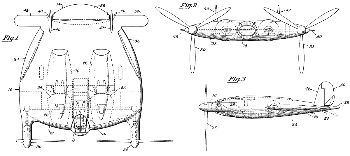
Charles Zimmerman’s fighter aircraft from a patent application submitted in 1940. Although the drawing shows fixed horizontal stabilizers (45/50) and skewed ailerons (34/36), the patent also covered the configuration used on the Vought XF5U. Note the prone position of the pilot, and the guns around the cockpit.
The Vought XF5U was comprised of a rigid aluminum airframe covered with Metalite. Metalite was light and strong and formed by a layer of balsa wood bonded between two thin layers of aluminum. The XF5U had the same basic configuration as the V-173 but was much heavier and more complex.
The XF5U’s entire disk-shaped fuselage provided lift. The aircraft had a short wingspan, and large counter-rotating propellers were placed at the wingtips. At the rear of the aircraft were two vertical tails, and between them were two stabilizing flaps. When the aircraft was near the ground, air loads acted on spring-loaded struts to automatically deflect the stabilizing flaps up and allow air to escape from under the aircraft. The stabilizing flaps enhanced aircraft control during landing. On the sides of the XF5U were hydraulically-boosted, all-moving ailavators (combination ailerons and elevators). The ailavators had a straight leading edge, rather than the swept leading edge used on the V-173’s ailavators. Two large balance weights projected forward of each ailavator’s leading edge.
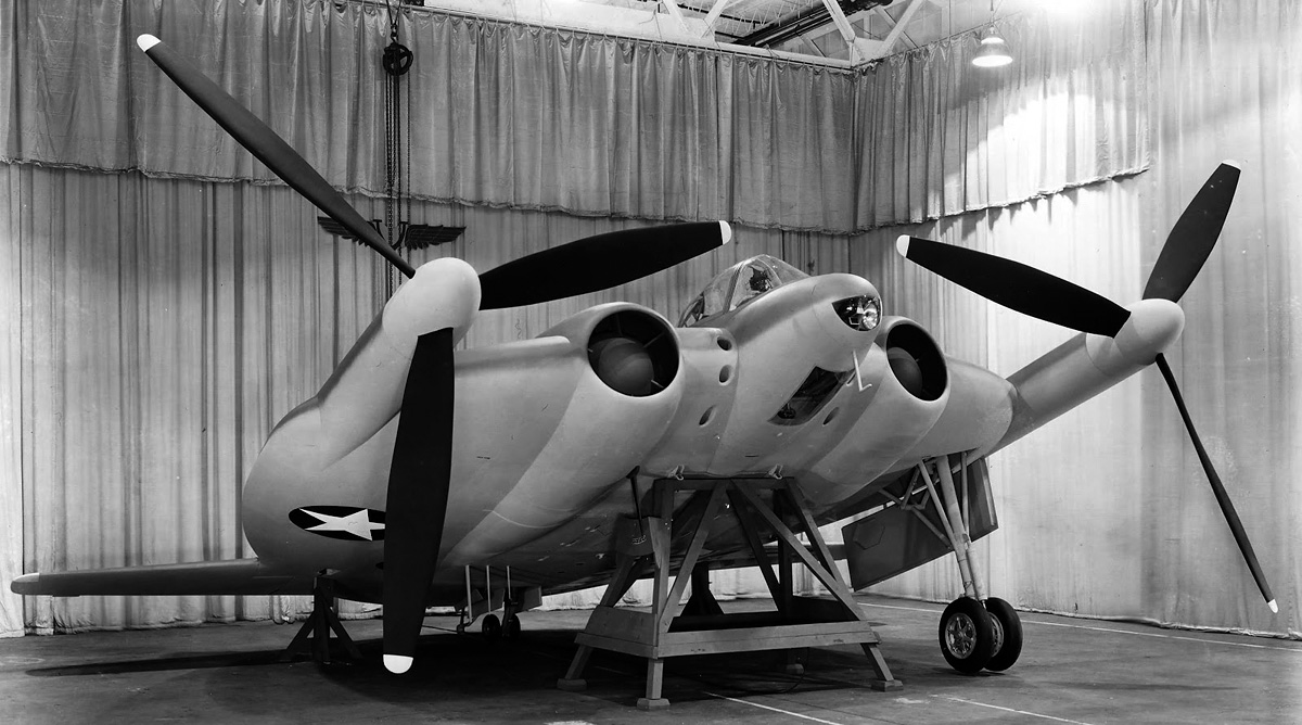
The XF5U mockup was finished in June 1943. Note the gun ports by the cockpit. The mockup had three-blade propellers and single main gear doors, items that differed from what was ultimately used on the prototype. The acrylic panel under the nose was most likely to improve ground visibility, like the glazing on the V-173. However, test pilots reported that the glazing was not useful.
Zimmerman originally proposed a prone position for the pilot, but a conventional seating position was chosen. The pilot was situated just in front of the leading edge and enclosed in a bubble canopy. Some sources state that an ejection seat was to be used, but no mention of one has been found in Vought documents, and an ejection seat does not appear to have been installed in the XF5U-1 prototype. The cockpit was accessed via a series of recessed steps that led up the back of the aircraft. The acrylic nose of the XF5U housed the gun camera and had provisions for landing and approach lights.
The aircraft’s landing gear was fully retractable, including the double-wheeled tailwheel. The main gear had a track of 15 ft 11.5 in (4.9 m). A small hump in the outer gear doors covered the outboard double main gear wheel. The long gear gave the aircraft an 18.7 degree ground angle. A catapult bridle could be attached to the aircraft’s main gear to facilitate catapult-assisted launches from aircraft carriers. For carrier landings, an arresting hook deployed from the XF5U’s upper surface and hung over the rear of the aircraft. Armament for the XF5U consisted of six .50-cal machine guns—three guns stacked on each side of the cockpit—with 400 rpg. The lower four guns were interchangeable with 20 mm cannons, but the proposed rpg for the cannons has not been found. Two hardpoints under the aircraft could each accommodate a 1,000 lb (454 kg) bomb. No armament was installed on the prototype.
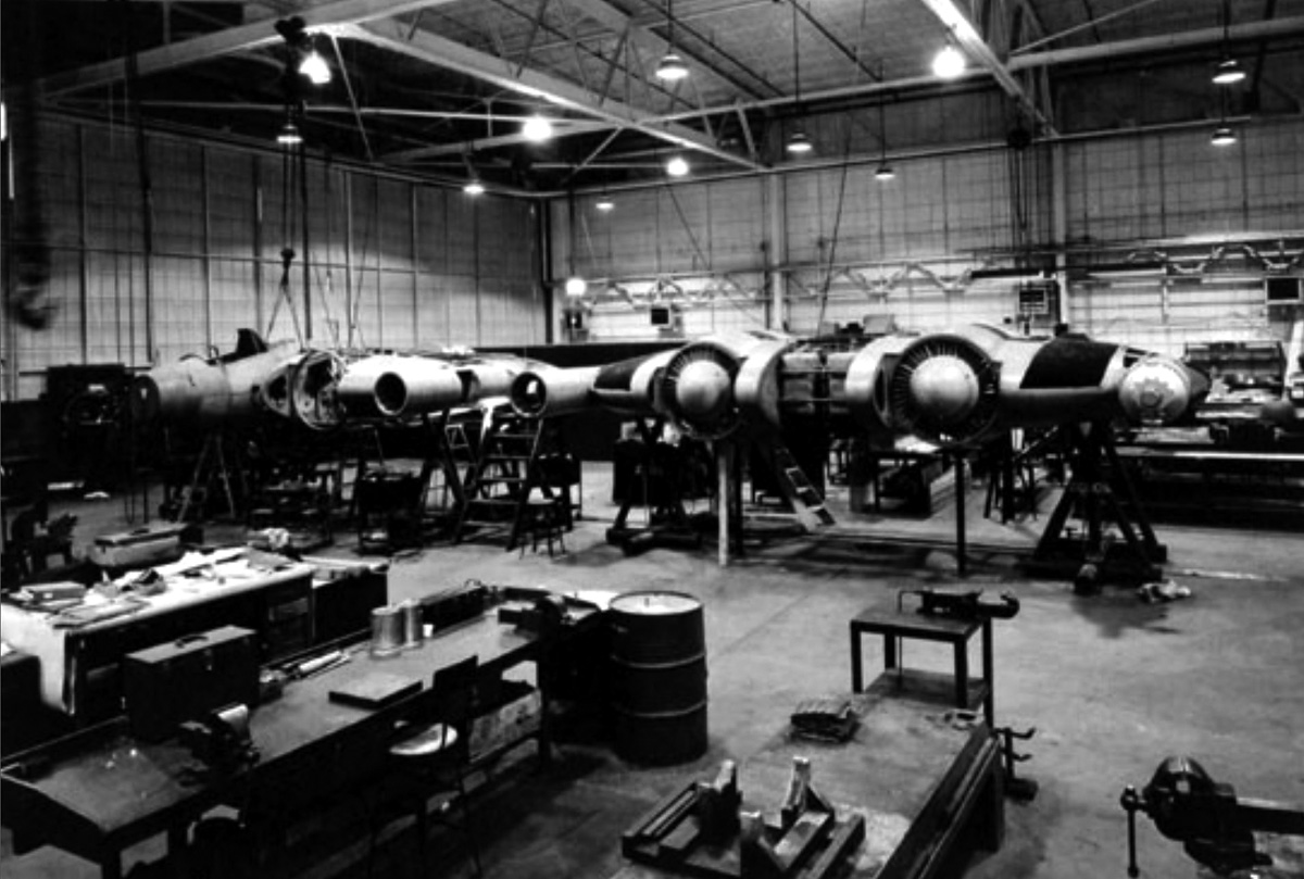
The two XF5Us under construction. The left airframe was used for static testing, and the right airframe was the test flight aircraft. The engine cooling fans and oil tanks can be seen on the right airframe.
Originally, the XF5U was to be powered by two 14-cylinder, 1,600 hp (1,193 kW) Pratt & Whitney (P&W) R-2000-2 engines. It appears P&W stopped development of the -2 engine, and the 1,350 hp (1,007 kW) R-2000-7 was substituted sometime in 1945. The engines were buried in the aircraft’s fuselage, and engine-driven cooling fans brought in air through intakes in the aircraft’s leading edge. Cooling air exit flaps were located on the engine nacelles on both the upper and lower fuselage. An exit flap for intercooler air was located farther back on the top side of each nacelle.
Engine power was delivered to the propellers via a complex set of shafts and right angle gear drives. A two-speed gear reduction provided a .403 speed reduction for takeoff and a .177 reduction for cruising and high-speed flight. With the engines operating at 2,700 rpm (1,350 hp / 1,077 kW) at maximum takeoff power, the propellers turned at 1,088 rpm. At maximum cruise with the engines at 2,350 rpm (735 hp / 548 kW), the propellers turned at 416 rpm.
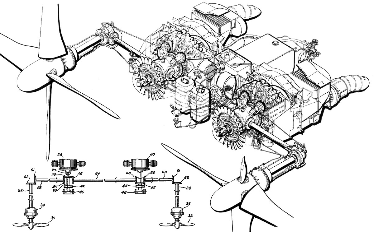
The complex power drive of the XF5U was the aircraft’s downfall. The system was unlikely to work flawlessly, and the Navy chose to use its post-war budget on jet aircraft rather than testing the XF5U. The inset drawing is from Zimmerman’s patent outlining the propeller drive.
A power cross shaft was mounted between the gearboxes on the front of the engines. In the event of an engine failure, the dead engine would be automatically declutched, and the cross shaft would distribute power from the functioning engine to both propellers. The two engines were declutched from the propeller drive at startup. The clutches were hydraulically engaged, and a loss of fluid pressure caused the clutch to disengage. The engines were controlled by a single throttle lever and could not be operated independently (except at startup).
By November 1943, the ongoing flight tests of the V-173 indicated that special articulating (or flapping) propellers would be needed on the XF5U. Propeller articulation was incorporated into the hub by positioning one two-blade pair of propellers in front of the second two-blade pair. The extra room provided the space needed for the 10 degrees of articulation and the linkages for propeller control. As one blade of a pair articulated forward, the opposite blade of the pair moved aft. To relieve the load and minimize vibrations, the propeller hub mechanism caused the blade pitch to decrease as the blade articulated forward and to increase as the blade moved aft. The XF5U’s wide-cord propellers were 16 ft (4.9 m) in diameter, made from Pregwood (plastic-impregnated wood), and built by Vought. The propellers were finished with a black cuff, a woodgrain blade, and a yellow tip. The pitch of the propellers was controlled by a single lever and could not be independently controlled; the set pitch of all blades changed simultaneously. If both engines failed, the propellers would feather automatically. Construction of the special propellers was delayed, and propellers from a F4U-4 Corsair were temporarily fitted to enable ground testing to begin.
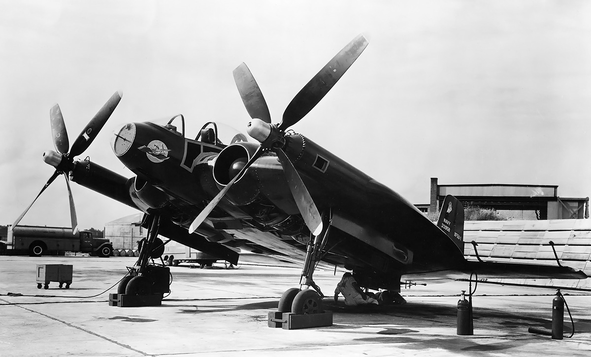
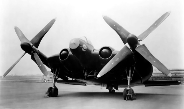
The completed XF5U ready for primary engine runs with F4U-4 propellers. The aircraft was completed over a year before the articulating propellers were finished. Had the propellers been ready sooner, it is likely the XF5U would have been transported to Edwards Air Force Base for testing in late 1945.
The XF5U had a wingspan of 23 ft 4 in (7.1 m) but was 32 ft 6 in (9.9 m) wide from ailavator to ailavator and 36 ft 5 in (8.1 m) from propeller tip to propeller tip. Each ailavator had a span of about 8 ft 4 in (2.5 m). The aircraft was 28 ft 7.5 in (8.7 m) long and 14 ft 9 in (4.5 m) tall. The XF5U could take off in 710 ft (216 m) with no headwind and in 300 ft (91 m) with a 35 mph (56 km/h) headwind. The aircraft had a top speed of 425 mph (684 km/h) and a slow flight speed of 40 mph (64 km/h). Initial rate of climb was 3,000 fpm (15.2 m/s) at 175 mph (282 km/h), and the XF5U had a ceiling of 32,000 ft (9,754 m). A single tank located in the middle of the aircraft carried 261 gallons (988 L) of fuel. The internal fuel gave the XF5U a range of 597 miles (961 km), but with two 150-gallon (568-L) drop tanks added to the aircraft’s hardpoints, range increased to 1,152 miles (1,854 km). The XF5U had an empty weight of 14,550 lb (6,600), a normal weight of 16,802 lb (7,621 kg), and a maximum weight of 18,917 lb (8,581 kg).
The XF5U with its special, wide-cord, articulating propellers installed. Note the winged Vought logo on the propellers. The purpose of the bottles under the fuselage is not clear. The aircraft used compressed air for emergency extension of the landing gear and tail hook. Perhaps that system was being tested. Note that the inner main gear doors have been removed.
A wooden mockup of the XF5U was inspected by the Navy in June 1943. At this time, the mockup had narrow, three-blade propellers that were very similar to those used on the V-173. The XF5U’s complex systems and unconventional layout delayed its construction, which was further stagnated by higher priority work during World War II. The aircraft was rolled out on 20 August 1945 with the F4U-4 propellers installed. Some ground runs were undertaken, but more serious tests had to wait until Vought finished the special articulating propellers in late 1946.
The aircraft started taxi tests on 3 February 1947, but concerns over the XF5U’s propeller drive quickly surfaced. Vought’s chief test pilot Boone T. Guyton made at least one small hop into the air, but no serious test flights were attempted. The test pilots and Vought felt that the only suitable place for test flying the radical aircraft with its unproven gearboxes and propellers was at Edwards Air Force Base in California. Given the XF5U’s construction, the aircraft could not be disassembled, and it was too large to be transported over roads. The only option was to ship the XF5U to California via the Panama Canal. Faced with the expensive transportation request, no urgent need for the XF5U, questions about propeller drive reliability, and the emergence of jet aircraft, the Navy cancelled all further XF5U project activity on 17 March 1947.
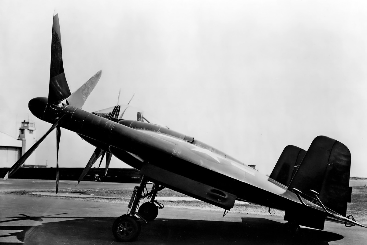
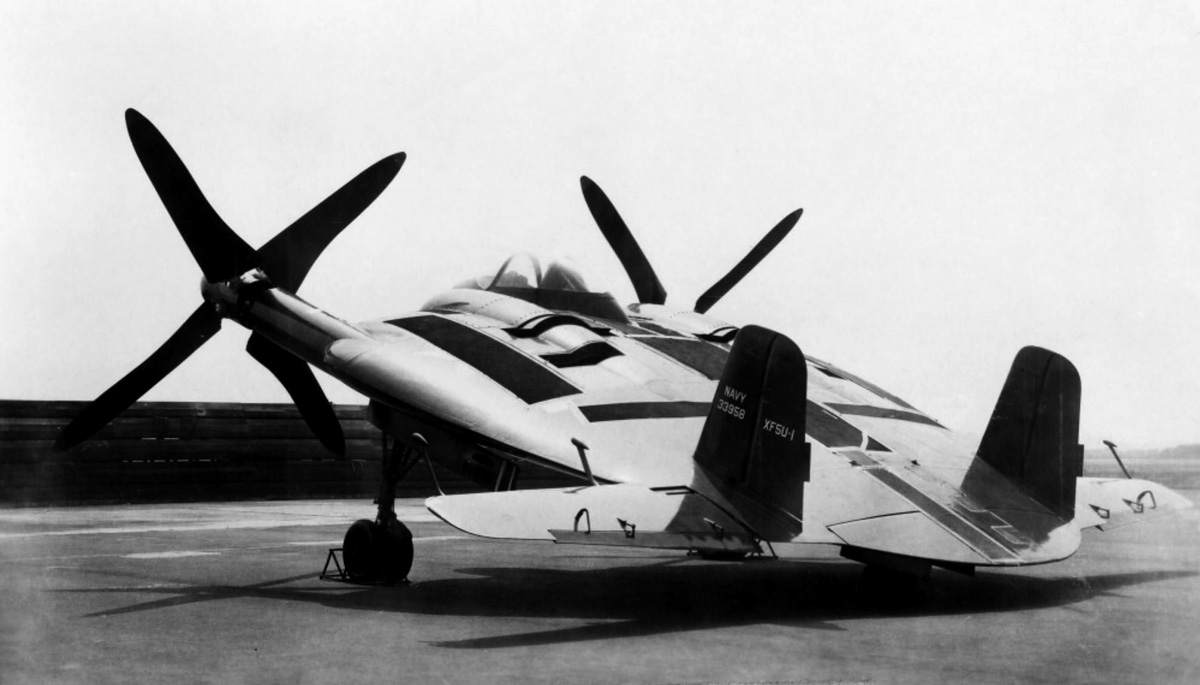
This side view of the XF5U shows how the propeller blades were staggered. Note the balance weights on the ailavator, the hump on the gear door, and the slightly open engine cooling air exit flap on the upper fuselage. Strangely, the tail markings appear to have been removed from the photo.
With the original 1,600 hp (1,193 kW) P&W R-2000-2 engines, the XF5U had a forecasted top speed of 460 mph (740 km/h) and a slow speed of 20 mph (32 km/h). The aircraft had a 3,590 fpm (18.2 m/s) initial rate of climb and a service ceiling of 34,500 ft (10,516 m). With a fuel load listed at 300 gallons (1,136 L), the aircraft would have a 710-mile (1,143-km) range. To increase the XF5U’s performance and try to keep the program alive, Vought proposed a turbine-powered model to the Navy, designated VS-341 (or V-341). While it is not entirely clear which engine was selected, the engine depicted in a technical drawing closely resembles the 2,200 hp (1,641 kW) General Electric T31 (TG-100) turboprop. The estimated performance of the VS-341 was a top speed of 550 mph (885 km/h) and a slow speed of 0 mph (0 km/h)—figures that would allow the VS-341 to achieve Zimmerman’s dream of a high-speed, vertical takeoff and landing (VTOL) aircraft.
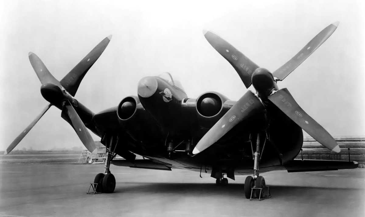
Rear view of the XF5U shows padding taped to the aircraft to protect its Metalite surface. The engine cooling air exit flaps are open. The intercooler doors have been removed, which aided engine cooling during ground runs. Note the tail markings on the aircraft.
The XF5U intended for flight testing (BuNo 33958) was smashed by a wrecking ball shortly after the program was cancelled. The XF5U’s rigid airframe withstood the initial blows, but there was no saving the aircraft; its remains were sold for scrap. At the time, the second XF5U (BuNo 33959) had already been destroyed during static tests.
Zimmerman’s aircraft were given several nicknames during their development: Zimmer’s-Skimmer, Flying Flapjack, and Flying Pancake. It is unfortunate that a radical aircraft so close to flight testing was not actually flown. Zimmerman continued to work on VTOL aircraft for the rest of his career.

To bring the XF5U into the jet age, Vought designed the turbine-powered VS-341. The aircraft had the same basic layout as the XF5U. Note the power cross shaft extending from the gearbox toward the other engine.
Sources:
– Chance Vought V-173 and XF5U-1 Flying Pancakes by Art Schoeni and Steve Ginter (1992)
– Aeroplanes Vought 1917–1977 by Gerard P. Morgan (1978)
– XF5U-1 Preliminary Pilot’s Handbook by Chance Vought Aircraft (30 September 1946)
– XF5U-1 Illustrated Assembly Breakdown by Chance Vought Aircraft (1 January 1945)
– Langley Full-Scale Tunnel Investigation of a 1/3-scale Model of the Chance Vought XF5U-1 Airplane by Roy H. Lange, Bennie W. Cocke Jr., and Anthony J. Proterra (1946)
– “Airplane of Low Aspect Ratio” US patent 2,431,293 by Charles H. Zimmerman (applied 18 December 1940)
– “Single or Multiengined Drive for Plural Airscrews” US patent 2,462,824 by Charles H. Zimmerman (applied 3 November 1944)
– “The Flying Flapjack” by Gilbert Paust Mechanix Illustrated (May 1947)
– http://www.vought.org/special/html/sxf5u.html
– http://www.vought.org/products/html/xf5u-1spec.html

“Given the XF5U’s construction, the aircraft could not be disassembled” – could this have been one of the reasons why the project was cancelled? If a plane enters military service, then they will be a need to replace damaged parts, as well as regular maintenance.
Hello Graham – I don’t think so. With most aircraft, you can remove the wings and tail from the fuselage. But the entire XF5U was a combination wing and fuselage. There were access panels for maintenance and damaged areas could be repaired, but the aircraft could not be broken down into smaller sections. I think the XF5U was cancelled because everyone knew there would be major issues with the gearboxes, the war was over, and jet aircraft were in production. Even so, I think it should have been preserved rather than scrapped.
First thing I have to say is great job on this article. I am a big fan of the XF5U-Flying Flapjack and it was a shame it was never fully tested and analyzed. I have some several questions about the Flapjack concerning speculations of a possible modern version of it.
Questions:
Could the “complicated” shaft system be replaced by…?
-a universal joint system(Optimal)
-a chain system similar to that of a bike(Unsure)
since adding to many parts(gears/shafts/cogs) was deemed to complex
Would a jet assisted Flapjack be viable as portrayed in this magazine?
Click to access flying_flapjack_mechanix_05_1947.pdf
Would a modernized version of the flapjack be viable?
-Upgraded Engines
-Fly by wire systems
-Higher Fuel Capacity?
Like speculated in this Quora post
https://www.quora.com/If-Charles-Zimmermans-Vought-XF5U-flying-flapjack-were-built-using-todays-technology-better-engines-fly-by-wire-composite-structure-etc-would-it-be-a-viable-aircraft-or-drone
The amazing properties have been the Flapjacks trait in standing out from other prototype aircraft. What are some limitations of this configuration for an aircraft?
Ex:
-Fuel
I would love to hear your thoughts and ideas on these questions. Thanks
-Kin
Hello Kin,
Thank you for the kind words, and I’m glad you liked the article. Below you will find my answers to your questions.
Could the “complicated” shaft system be replaced by a universal joint system or a chain system?
— I do not think so. Universal joints do not like operating at an angle beyond 30 degrees and the XF5U had two 90 degree bends. I don’t see how to make universal joints work. Chain drives could work to deliver the power, but the chains and associated parts would weight a lot more than the shafts. In addition to the weight, I think the chains would have issues operating with the constantly changing G forces a fighter aircraft experiences. If a chain failed, it would probably rip apart 1/4 to 1/2 of the aircraft.
Would a jet assisted Flapjack be viable? Would a modernized version of the flapjack be viable?
— Not jet assisted, but I think a turboprop version would be possible. Today’s powerful turboprops output more power than the R-2000 engines in the XF5U. The turboprops are also smaller and lighter. Turboprop engines could be placed at the wingtips of a modern-day XF5U and either drive the propellers directly or through extension shafts. A cross shaft could still be used to synchronize the propellers and transfer power if an engine failed.
While I think it is possible, I do not think it is practical. The AV8 Harrier and F-35 Lightning II outmatch a turboprop-XF5U in every way. In the attack role, I think the aircraft would be too fragile. A bullet hit to the very large propellers could cause serious issues and the loss of the aircraft. Yes, helicopters can take a few bullets to the rotors and keep going, but during an attack run, an XF5U-style aircraft would be presenting two large propeller discs to the target it is attacking. A-10 Thunderbolts can take a lot of damage and still fly. I cannot think of a practical reason the armed forces would want a piloted XF5U-style aircraft in this day and age. Even scaled up to compete with a V-22 Osprey, I think the Osprey would prove to be more versatile.
There could be some medium-size UAV/drone applications. Smaller drones are hand-launched. Larger drones operate like standard aircraft. A medium-size XF5U drone could operate from streets or fields. But, the military funds a lot of things and modern-day aerospace companies employ a lot of smart people. I think if there were a practical application for an XF5U-style drone or aircraft, one would have been developed.
What are some limitations of this configuration for an aircraft?
— The V-173 demonstrated the viability of Zimmerman’s concept. I think the limitations would be a high cost to develop the aircraft, excessive vibrations from the power system and propellers, major questions about control and survivability after a mechanical failure, and high maintenance requirements for the complex system.
If the US Navy really felt they had something good, they would have covered the costs to test the XF5U. Regardless of how much I wish they did and how much I like the aircraft, the fact that no other aircraft have been built like the XF5U indicates to me that it is simply not practical; at least not yet.
Best regards,
Bill Pearce
Speculative Questions:
Would an electric version of the Flapjack be possible in the near future given the advances in the field of batteries and electric vehicles? Taking in consideration advantages of electric vehicles over fuel powered engines.
Recently I was digging around the internet for more disk shaped aircraft and I stumbled upon a recent invention called the Geobat. Which is a circular disk aircraft patent that has yet to have a human seated craft but small UAVs based on the design have flown.
http://www.tested.com/tech/robots/460940-designing-new-breed-flying-disc/
Would it be possible to do an article about this interesting aircraft or even how it compares to the flying pancake/flapjack
Regards, Kin
Hello Kin,
Would an electric version of the Flapjack be possible in the near future given the advances in the field of batteries and electric vehicles?
— Probably. I think piloted-electric aircraft are in their infancy and still have a way to go before things can get too exotic. I think a cross shaft would still be needed in case of failure, and that would complicate things beyond simple electric motors. But, UAV/drone applications should work well.
Would it be possible to do an article about the Geobat or even how it compares to the flying pancake/flapjack?
— I don’t think I would do an article on the Geobat as I prefer to write about old stuff. Besides, Aerobat Aviation is still writing their own history, and I wish them the best of luck. As far as comparing the Geobat with the V-173/XF5U, that is also a bit difficult until Aerobat Aviation builds some larger-scale aircraft. Things are not always scalable, and a piloted Geobat may differ a great deal from the UAVs Aerobat Aviation have developed.
Regards,
Bill
Much talk about the Zimmerman/Vought planes, ignores some things, and mis-states others.
The contest for a STOL/VTOL plane which Zimmerman was in; the Arup planes put on an impressive performance for NACA, the Army and he CAA. Zimmerman worked for NACA and was on the inspection team that saw the Arup planes.
They attracted no orders or requests for licensing and were ignored until the Navy took interest in the proven low aspect ratio planform prototyped by the Arup, in a fighter.
Zimmerman’s work always went towards his tail-sitting VTOL contra-prop ideas (but never actually trying to build for VTOL) Meanwhile the Arup planes were everything the Navy was asking for and which Zimerman’s system claimed, no need for the extra complexity.
The Arup planes had no wing-tip contra-props, they didn’t need it any more than a navy flapjack would, because they did not suffer from excessively high drag during cruise & dash regimes.
The enormous wing-tip wrap-around of a short-aspect-ratio craft at high A, meets with the flow over the top of the LE, and give extra lift as the “trick” of low-aspect ratio silly slow stall speeds at high A.
At cruise low A, they’re slippery and fast as an all-wing is expected to be, the Arup were nimble, and like the V-173, un-stall-spin-able.
The Hatfield “Little Bird” series on the ’80s proved all the claims of the Arup series. Low landing speeds and power, sleek in cruise, easier to make and service. Durable like the Arup and the V-173 (minus the gearing and complexity).
At the same time Vought took the Navy into the un-necessary contra-wing-tip-vortex prop misadventure, the Navy apparently ignored the Boeing proposal for the Navy STOL fighter. The Boeing model 390 would probably have been steel-tube and wood & fabric. Diagrams show what looks like a straight 6 automobile engine buried behind/under the pilot, and a two-blade wooden normal prop at the nose and no nonsense about supposed wing-tip vortex in cruise (you want it, in high-A flight. It’s the point of it with short-aspect-ratio).
The Boeing plane would have been rather like the Arup S-2. Elliptical “tapered” wing rather than a straight leading edge like the Arup. Also like the little Boeing test plane is the successfully flying modern Rowe UFO (“Useless Flying Object”) with a completely circular wing.
That would have been followed by the Boeing model 396. About the size and capability of a Bearcat with more range and payload and speed, 500+kts, and 40kts landing speed. Normal contra-props of the time at the nose. A fin but no horizontal tail (which the Arup S-4 was very successful with, the S-2 without)
While the Zimmerman plane and its un-necessary flapping props strongly evoked the giggle-factor in aviation, the Boeing plane was sinister if anything, as a fighter. The strangeness of the nearly circular planform did not evoke humor (nausea and fainting, perhaps)… Seeing its performance would have been a game-changer. All navy planes would have its planform soon, and after the Arup patents expire, all of Civil aviation. (Or can a patent holder sue after 14 years?)
We usually hear that the advent of the jet age killed this STOL flapjack idea. But the Navy was still building the Avenger and the Skyraider for years after, and operated them until the ’70s along with the piston-prop S-2/C-1/E-1. The Navy is still operating turbo-prop planes., even if it’s difficult to see squeezing much of this concept into a supersonic air superiority jet. Horton designed one, of a unitary wing/body (American W Horton in the 1950s, designer of a “wingless” lifting body plane that would have been successful if it attracted any buyers to overcome the giggle factor and “not invented here” which aerospace is rife with)
Apparently Chance-Vought tried to save the naval flapjack STOL fighter, with their “Jet Skimmer”. I’d heard about possible jet advancement of the concept, but like the Boeing flapjacks, a model kit is almost the only source I can find online info about it. It proves that the design was still viable as a jet, and would have been superior to other things being built at the time. More like the Boeing plane might have evolved into, than anything of Zimmerman’s VTOL ideas.
Why the Navy and Vought thought it worthwhile to venture off in search of Zimmerman’s VTOL toys, instead of building the Boeing plane as an honest appraisal of the very promising Arup, we can’t know.