EP0057914A2 - Video-recorder with a plurality of control elements - Google Patents
Video-recorder with a plurality of control elements Download PDFInfo
- Publication number
- EP0057914A2 EP0057914A2 EP82100797A EP82100797A EP0057914A2 EP 0057914 A2 EP0057914 A2 EP 0057914A2 EP 82100797 A EP82100797 A EP 82100797A EP 82100797 A EP82100797 A EP 82100797A EP 0057914 A2 EP0057914 A2 EP 0057914A2
- Authority
- EP
- European Patent Office
- Prior art keywords
- recorder
- video
- recorder according
- operating
- playback device
- Prior art date
- Legal status (The legal status is an assumption and is not a legal conclusion. Google has not performed a legal analysis and makes no representation as to the accuracy of the status listed.)
- Granted
Links
- 238000012544 monitoring process Methods 0.000 claims abstract 2
- 239000002131 composite material Substances 0.000 claims description 4
- 230000005236 sound signal Effects 0.000 claims description 4
- 238000011022 operating instruction Methods 0.000 abstract description 5
- 230000006870 function Effects 0.000 description 8
- 238000012790 confirmation Methods 0.000 description 2
- 238000000034 method Methods 0.000 description 2
- 238000012545 processing Methods 0.000 description 2
- 238000013024 troubleshooting Methods 0.000 description 2
- 238000002604 ultrasonography Methods 0.000 description 2
- 230000032683 aging Effects 0.000 description 1
- 230000015572 biosynthetic process Effects 0.000 description 1
- 238000012937 correction Methods 0.000 description 1
- 230000007547 defect Effects 0.000 description 1
- 238000011161 development Methods 0.000 description 1
- 230000018109 developmental process Effects 0.000 description 1
- 238000010586 diagram Methods 0.000 description 1
- 239000010453 quartz Substances 0.000 description 1
- VYPSYNLAJGMNEJ-UHFFFAOYSA-N silicon dioxide Inorganic materials O=[Si]=O VYPSYNLAJGMNEJ-UHFFFAOYSA-N 0.000 description 1
- 238000003786 synthesis reaction Methods 0.000 description 1
Images

Classifications
-
- H—ELECTRICITY
- H04—ELECTRIC COMMUNICATION TECHNIQUE
- H04N—PICTORIAL COMMUNICATION, e.g. TELEVISION
- H04N5/00—Details of television systems
- H04N5/76—Television signal recording
- H04N5/765—Interface circuits between an apparatus for recording and another apparatus
- H04N5/775—Interface circuits between an apparatus for recording and another apparatus between a recording apparatus and a television receiver
-
- G—PHYSICS
- G07—CHECKING-DEVICES
- G07C—TIME OR ATTENDANCE REGISTERS; REGISTERING OR INDICATING THE WORKING OF MACHINES; GENERATING RANDOM NUMBERS; VOTING OR LOTTERY APPARATUS; ARRANGEMENTS, SYSTEMS OR APPARATUS FOR CHECKING NOT PROVIDED FOR ELSEWHERE
- G07C3/00—Registering or indicating the condition or the working of machines or other apparatus, other than vehicles
- G07C3/02—Registering or indicating working or idle time only
- G07C3/04—Registering or indicating working or idle time only using counting means or digital clocks
-
- G—PHYSICS
- G11—INFORMATION STORAGE
- G11B—INFORMATION STORAGE BASED ON RELATIVE MOVEMENT BETWEEN RECORD CARRIER AND TRANSDUCER
- G11B15/00—Driving, starting or stopping record carriers of filamentary or web form; Driving both such record carriers and heads; Guiding such record carriers or containers therefor; Control thereof; Control of operating function
- G11B15/005—Programmed access in sequence to indexed parts of tracks of operating tapes, by driving or guiding the tape
-
- G—PHYSICS
- G11—INFORMATION STORAGE
- G11B—INFORMATION STORAGE BASED ON RELATIVE MOVEMENT BETWEEN RECORD CARRIER AND TRANSDUCER
- G11B27/00—Editing; Indexing; Addressing; Timing or synchronising; Monitoring; Measuring tape travel
- G11B27/10—Indexing; Addressing; Timing or synchronising; Measuring tape travel
- G11B27/34—Indicating arrangements
-
- G—PHYSICS
- G11—INFORMATION STORAGE
- G11B—INFORMATION STORAGE BASED ON RELATIVE MOVEMENT BETWEEN RECORD CARRIER AND TRANSDUCER
- G11B33/00—Constructional parts, details or accessories not provided for in the other groups of this subclass
- G11B33/10—Indicating arrangements; Warning arrangements
Definitions
- the invention has for its object to simplify the operation of a video recorder.
- a commercially available television receiver can be used to visually or acoustically convey to the operator the necessary instructions for operation in a clear and understandable form.
- the pediatrician can then choose between the various options according to his wishes.
- the operator therefore always receives guidelines for correct operation.
- the operating instructions are therefore stored in the video recorder and therefore cannot be lost.
- the information displayed optically or acoustically can be of different types. They can include a prompt to the operator to do something specific. They can contain a confirmation that the operating function performed was understandable for the recorder and was used. They can also indicate that there is obviously an incorrect operation and the operator should repeat the operation.
- the invention can extend to all types of operation occurring in practice. Operation can be done via. an ultrasonic or infrared remote control transmitter or the keypad included in the recorder, which can be controlled via LED / LCD display.
- the invention is also particularly advantageous when programming the VCRs. This consists of station programming with station search, fine tuning, direct channel selection and storage of tuning information. It also contains the drive and time programming, the time, switch-on-switch-off programming with the desired drive mode, such as recording and playback, as well as forward and rewind as well as dialing. The programming also enables corrections at any point on the tape;
- the operator can also enter a table of contents of the video cassette into a memory of the video recorder.
- the playback device then serves as a monitor for the memory.
- This data can then be stored on the video cassette.
- the data entered is e.g. stored in the page memory of a data / CVBS converter and checked on the playback device.
- the television picture to be seen is transmitted from this converter via the audio / video control unit to the drive unit, which then writes the data onto the cassette.
- the signals supplied by the video recorder to the playback device can contain a text, a certain graphic, tables, operating symbols as well as speech and other sound signals in coded and uncoded form.
- the signal can be sent from the video recorder to the playback device, for example: a commercially available television receiver, as a composite signal to the so-called AV socket.
- an LF signal for the reproduction of speech and sound is also transmitted.
- This signal can be obtained in the video recorder in a circuit for the synthetic generation of speech signals, a so-called speech synthesis module.
- the signal can also be fed to the antenna socket of a television receiver by means of a modulated carrier.
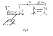
- FIG. 1 shows in principle the interconnection between video recorder and television receiver for establishing the dialogue
- FIG. 2 shows a block diagram of the video recorder in which the solution according to the invention is implemented.
- the video recorder 25 is operated remotely by the remote control transmitter 26 in all its functions.
- the video recorder 25 can receive, process and record an RF television broadcast signal via the antenna 20.
- the video recorder 25 delivers signals to the commercially available television receiver 21. These signals contain information and feedback about the operation and are reproduced on the screen and / or via the loudspeaker.
- This signal can be supplied in the form of a carrier modulated with the signals via line 19 to the antenna socket of television receiver 21 or as a composite signal and LF audio signal via line 18 to an AV socket of television receiver 21.
- the television receiver 21 gives the operator the request "please select a channel". After the channel has been selected, e.g. a confirmation is given that the channel information has been understood and evaluated and thus the receiving part of the video recorder is tuned to a specific channel.
- the RF signal received by the antenna 20 of a television transmitter reaches the tuning unit 6. From there it can be switched directly to an output of the video recorder 25 and reach the antenna socket of the television receiver 21 via the line 19.
- the received signal is decoded into image and sound signals and recorded on the video tape via the control unit 5 and the recording unit 2 with the drive unit 1.
- These signals can additionally be routed via the control unit 5 to the AV output of the video recorder 25 and from there via AV lines 18 to the television receiver 21. This switching of the received signals to the television receiver 21 can also take place without recording the signals on the video tape.
- the microprocessor 11 controls the data / CVBS converter 9 with data which are sent to the control unit 5 as a CVBS signal. From there, this signal can reach the RF modulator 3 and, via line 19, the antenna socket of the television receiver 21. The signal can also be fed directly to the television receiver 21 via the AV line 18. With these functions, the signals can be recorded simultaneously via the recording unit 2 and the drive unit 1.
- Speech signals are generated as follows.
- the microprocessor 11 operates the speech generator 12 with data which arrive at the control unit 5 as an LF signal. These can additionally be transmitted alone and / or together with the composite signal of the converter 9, which is switched accordingly by the control unit 5, via the AV line 18 to the television receiver 21.
- the data can also be over the RF modulator 25 and the line 19 of the antenna socket of the television receiver 21 are supplied.
- the signal can be recorded on the video tape via the recording unit 2 and the drive unit 1.
- the AV signal is fed from the drive unit 1 via the control unit 5 to the AV output and from there via the AV line 18 to the television receiver 21.
- the signal can also reach the RF modulator 3 and from there be fed to the television receiver 21 as a modulated carrier via the line 19.
- the video recorder 25 can be operated via the keyboard 16 on the video recorder.
- the query takes place via the control unit 15 for the keyboard, from which data is exchanged with the microprocessor 11.
- the display of the operated buttons and the results desired thereby is carried out via the control unit 15, which is operated by the microprocessor 11, by means of a display unit 17 in an LED / LCD version.
- the video recorder 25 can also be operated by the remote control transmitter 26 shown in FIG. 1 via ultrasound (US) or infrared (IR). These signals are received and amplified by the preamplifier 13 and converted into digital signals in the remote control transmitter and decoder 14. These signals are then taken over by the microprocessor 11 for further processing.
- US ultrasound
- IR infrared
- the keys operated in each case and the results desired thereby are passed from the microprocessor 11 in the form of data to the converter 9 and / or speech generator 12. From their outputs they are switched to the control unit 5 and via the AV output and the lines 18 fed to the television receiver 21. These data can additionally be recorded on the video tape via the control unit 5, the recording unit 2 and the drive unit 1.
- the control unit 8 is used to control recording, playback, drive functions and control of the tuning unit 6.
- the control unit 8 connects the microprocessor 11 to the playback unit 4, the recording unit 2 and the tuning unit 6. It serves to relieve the microprocessor 11.
- the microprocessor 11 gives operating commands to the control unit 8. From there they are forwarded to the connected modules.
- Various signals such as "Drive end”, “Dial reel finished”, “Start of tape” and the like sends the drive unit 1 to the control unit 8, which forwards these signals to the microprocessor 11, where they are then processed further.
- the programmable clock 7 for automatically switching on. Functions of the drive unit 1 are operated by a separate quartz as a time standard. Thanks to a special circuit, it is possible to continue operating with a lower power consumption even in the event of a power failure.
- the clock 7 is programmable in time, date and switching times.
- the memory 10 serves to store data in the manner already described, which can be entered, for example, by the remote control transmitter 26.
- the memory 10 contains a ROM memory, a RAM memory and a non-volatile memory EAROM.
- the chassis number is stored in the EAROM by the manufacturer and can be called up in the service position and made visible on the playback device.
- the microprocessor 11 Operating time counted and added to the operating time data contained in the memory 10 after completion of the operation or power failure and then stored in the EAROM. This can prevent misuse of the warranty claims at the expense of the manufacturer or the seller.
- the operating hours counter for the service provides valuable information on wear and defects that can occur due to the aging of the recorder.
Abstract
Description
Bedienung und Programmierung eines Videorecorders sind mit zunehmender Ausstattung im Laufe der Zeit beträchtlich schwieriger geworden, zumal gegenüber bisherigen Geräten der Unterhaltungselektronik viele neue Bedienungsfunktionen hinzugekommen sind. Oftmals müssen mehrere Bedienungselemente in einer bestimmten Reihenfolge oder sogar gleichzeitig betätigt werden. Bedienung und Programmierung sind dadurch selbst nach längerer Einübung schwierig. Die Hinweise für die richtige Bedienung des Recorders sind zwar in einer Bedienungsanleitung enthalten. Wegen der Vielzahl der Funktionen wie z.B. Senderprogrammierung, Programmierung einer Uhr, Aufzeichnung, Wiedergabe, Zeitraffung, Zeitdehnung, Standbildwiedergabe sind derartige Bedienungsanleitungen sehr-umfangreich. Das nötige Wissen über die Bedienung muß im allgemeinen häufig durch neues Lesen der Bedienungsanleitung erneut erworben werden. Die Bedienung derartiger Recorder bereitet in der Praxis selbst fachkundigen Bedienungspersonen oftmals Schwierigkeiten. Das kann u.a. zur Folge haben, daß z.B. eine gewünschte Sendung in Abwesenheit nicht aufgenommen oder eine bereits vorhandene Aufzeichnung in unerwünschter Weise gelöscht wird.Operating and programming a video recorder has become considerably more difficult with increasing equipment, especially since many new operating functions have been added to previous devices in entertainment electronics. Often, several controls have to be operated in a certain order or even simultaneously. Operation and programming are difficult even after long practice. The instructions for the correct operation of the recorder are contained in an operating manual. Because of the multitude of functions such as transmitter programming, programming a clock, recording, playback, time lapse, time stretching, still image playback, such operating instructions are very extensive. In general, the necessary knowledge about operation must often be acquired again by reading the operating instructions again. The operation of such recorders often creates difficulties even for skilled operators. Among other things, this can mean that, for example, a desired program is not absent recorded or an existing record is deleted in an undesirable manner.
Der Erfindung liegt die Aufgabe zugrunde, die Bedienung eines Videorecorders zu vereinfachen.The invention has for its object to simplify the operation of a video recorder.
Diese Aufgabe wird durch die im Anspruch 1 beschriebene Erfindung gelöst. Vorteilhafte Weiterbildungen der Erfindung sind in den Unteransprüchen beschrieben.This object is achieved by the invention described in claim 1. Advantageous developments of the invention are described in the subclaims.
Bei der Erfindung kann ein handelsüblicher Fernsehempfänger dazu ausgenutzt werden, dem Bedienenden in übersichtlicher und verständlicher Form die jeweils notwendigen Hinweise für die Bedienung optisch oder akustisch zu übermitteln. Der Pedienende kann dann zwischen den verschiedenen Möglichkeiten nach seinen Wünschen auswählen. Der Bedienende erhält somit immer einen Leitfaden für die jeweils richtige Bedienung. Die Bedienungsanleitung ist somit im Videorecorder gespeichert und kann daher auch nicht verlorengehen.In the invention, a commercially available television receiver can be used to visually or acoustically convey to the operator the necessary instructions for operation in a clear and understandable form. The pediatrician can then choose between the various options according to his wishes. The operator therefore always receives guidelines for correct operation. The operating instructions are therefore stored in the video recorder and therefore cannot be lost.
Die optisch oder akustisch dargestellten Informationen können unterschiedlicher Art sein. Sie können eine Aufforderung an den Bedienenden enthalten, etwas Bestimmtes zu tun. Sie können eine Bestätigung enthalten, daß die durchgeführte Bedienungsfunktion für den Recorder verständlich war und verwertet wurde. Sie können auch anzeigen, daß offensichtlich eine Fehlbedienung vorliegt und der Bedienende die Bedienung wiederholen sollte.The information displayed optically or acoustically can be of different types. They can include a prompt to the operator to do something specific. They can contain a confirmation that the operating function performed was understandable for the recorder and was used. They can also indicate that there is obviously an incorrect operation and the operator should repeat the operation.
Die Erfindung kann sich auf alle in der Praxis vorkommenden Arten der Bedienung erstrecken. Die Bedienung kann über. einen Ultraschall- oder Infrarot-Fernbedienungsgeber erfolgen oder auch durch das im Recorder enthaltene Tastenfeld, das über LED/LCD-Anzeige kontrolliert werden kann. Besonders vorteilhaft ist die Erfindung auch bei der Programmierung des Videorecorders. Diese besteht aus der Senderprogrammierung mit Sendersuchlauf, Feinabstimmung, direkter Kanalwahl und Speicherung der Abstimminformation. Sie enthält außerdem die Laufwerk- und Zeitprogrammierung, die Zeit-, Einschalt-Ausschalt-Programmierung mit dem dazu gewünschten Laufwerkmodus wie z.B. Aufnahme und Wiedergabe sowie den Vor- und Rücklauf und auch das Wählspulen. Die Programmierung ermöglicht-auch Korrekturen an beliebiger Stelle des Bandes;The invention can extend to all types of operation occurring in practice. Operation can be done via. an ultrasonic or infrared remote control transmitter or the keypad included in the recorder, which can be controlled via LED / LCD display. The invention is also particularly advantageous when programming the VCRs. This consists of station programming with station search, fine tuning, direct channel selection and storage of tuning information. It also contains the drive and time programming, the time, switch-on-switch-off programming with the desired drive mode, such as recording and playback, as well as forward and rewind as well as dialing. The programming also enables corrections at any point on the tape;
Es ist auch möglich, bestimmte Daten des Videorecorders vom Laufwerk oder aus der Elektronik zu messen und zu prüfen wie z.B. Drehzahl, Geschwindigkeit und Abstimmsignale, und diese Werte auf dem Wiedergabegerät anzuzeigen. Ebenso besteht die Möglichkeit, für Fehlersuche und Justierarbeiten ein Leitprogramm darzustellen. Auf diese Weise werden die Justierung und die Fehlersuche erleichtert und möglicherweise teure Eingriffe in den Videorecorder vermieden.It is also possible to measure and check certain data from the video recorder from the drive or from the electronics, e.g. Speed, speed and tuning signals, and display these values on the playback device. There is also the option of displaying a control program for troubleshooting and adjustment work. In this way, adjustment and troubleshooting are facilitated and potentially expensive interventions in the video recorder are avoided.
Der Bedienende kann auch ein Inhaltsverzeichnis der Videokassette in einen Speicher des Videorecorders eingeben. Das Wiedergabegerät dient dann anschließend als Monitor-für den Speicher. Anschließend können diese Daten auf-der Videokassette gespeichert werden. Bei diesem Vorgang werden die eingegebenen Daten z.B. im Seitenspeicher eines Daten/FBAS-Wandlers abgelegt und auf dem Wiedergabegerät kontrolliert. Das zu sehende Fernsehbild wird von diesem Wandler über die Audio/Video-Steuerungseinheit auf die Antriebseinheit übertragen, die dann die Daten auf die Kassette aufschreibt.The operator can also enter a table of contents of the video cassette into a memory of the video recorder. The playback device then serves as a monitor for the memory. This data can then be stored on the video cassette. In this process, the data entered is e.g. stored in the page memory of a data / CVBS converter and checked on the playback device. The television picture to be seen is transmitted from this converter via the audio / video control unit to the drive unit, which then writes the data onto the cassette.
Die vom Videorecorder zum Wiedergabegerät gelieferten Signale können einen Text, eine bestimmte Graphik, Tabellen, Bedienungssymbole sowie Sprache und sonstige Tonsignale in codierter und uncodierter Form enthalten.The signals supplied by the video recorder to the playback device can contain a text, a certain graphic, tables, operating symbols as well as speech and other sound signals in coded and uncoded form.
Das Signal kann vom Videorecorder dem Wiedergabegerät, z.B: einem handelsüblichen Fernsehempfänger, als FBAS-Signal zur sogenannten AV-Buchse zugeführt werden. In diesem Fall wird zusätzlich ein NF-Signal zur Wiedergabe von Sprache und Ton übertragen. Dieses Signal kann in dem Videorecorder in einer Schaltung zur synthetischen Erzeugung.von Sprachsignalen gewonnen werden, einem sogenannten Sprachsynthese-Modul. Das Signal kann auch mittels eines modulierten Trägers der Antennenbuchse eines Fernsehempfängers zugeführt werden.The signal can be sent from the video recorder to the playback device, for example: a commercially available television receiver, as a composite signal to the so-called AV socket. In this case, an LF signal for the reproduction of speech and sound is also transmitted. This signal can be obtained in the video recorder in a circuit for the synthetic generation of speech signals, a so-called speech synthesis module. The signal can also be fed to the antenna socket of a television receiver by means of a modulated carrier.
Ein Ausführungsbeispiel der Erfindung wird im folgenden anhand der Zeichnung erläutert. Darin zeigen Figur 1 im Prinzip die Zusammenschaltung zwischen Videorecorder und Fernsehempfänger zur Herstellung des Dialoges und Figur 2 ein Blockschaltbild des Videorecorders, in dem die erfindungsgemäße Lösung verwirklicht ist.An embodiment of the invention is explained below with reference to the drawing. 1 shows in principle the interconnection between video recorder and television receiver for establishing the dialogue and FIG. 2 shows a block diagram of the video recorder in which the solution according to the invention is implemented.
In Figur 1 wird der Videorecorder 25 durch den Fernbedienungsgeber 26 in allen seinen Funktionen fernbedient. Der Videorecorder 25 kann ein HF-Fernseh-Rundfunksignal über die Antenne 20 empfangen, verarbeiten und aufzeichnen. Während dieser Bedienung liefert der Videorecorder 25 Signale zu dem handelsüblichen Fernsehempfänger 21. Diese Signale enthalten Hinweise und Rückmeldungen über die Bedienung und werden auf dem Bildschirm und/oder über den Lautsprecher wiedergegeben. Diese Signalzuführung kann in Form eines mit den Signalen modulierten Trägers über die Leitung 19 zur Antennenbuchse des Fernsehempfängers 21 oder.als FBAS-Signal und NF-Tonsignal über die Leitung 18 zu einer AV-Buchse des Fernsehempfängers 21 erfolgen. Im dargestellten Beispiel gibt der Fernsehempfänger 21 dem Bedienenden die Aufforderung "Bitte Kanal wählen". Nach erfolgter Kanalwahl kann dann z.B. eine Bestätigung gegeben werden, daß die Kanalinformation verstanden und ausgewertet wurde und somit der Empfangsteil des Videorecorders auf einen bestimmten Kanal abgestimmt ist.In Figure 1, the
Anhand der Figur 2 werden nacheinander verschiedene Funktionen beschrieben.Various functions are described in succession with the aid of FIG.
In Figur 2 gelangt das von der Antenne 20 empfangene HF-Signal eines Fernsehsenderszur Abstimmeinheit 6. Von dort kann es direkt wieder auf einen Ausgang des Videorecorders 25 geschaltet werden und über die Leitung 19 zur Antennenbuchse des Fernsehempfängers 21 gelangen. In der Abstimmeinheit.6 wird das empfangene Signal in Bild- und Tonsignale decodiert und über die Steuereinheit 5 und die Aufzeichnungseinheit 2 mit der Antriebseinheit 1 auf dem Videoband aufgezeichnet. Diese Signale können zusätzlich über die Steuereinheit 5 zum AV-Ausgang des Videorecorders 25 und von dort über AV-Leitungen 18 zum Fernsehempfänger 21 geführt werden. Diese Durchschaltung der empfangenen Signale zum Fernsehempfänger 21 kann auch ohne Aufzeichnung der Signale auf dem Videoband erfolgen.In Figure 2, the RF signal received by the
Der Mikroprozessor 11 steuert den Daten/FBAS-Wandler 9 mit Daten, die als FBAS-Signal zur Steuereinheit 5 geleitet werden. Von dort kann dieses Signal zum HF-Modulator 3 und über die Leitung 19 zur Antennenbuchse des Fernsehempfängers 21 gelangen. Das Signal kann auch direkt über die AV-Leitung 18 dem Fernsehempfänger 21 zugeführt werden. Bei diesen Funktionen ist gleichzeitig eine Aufzeichnung der Signale über die Aufzeichnungseinheit 2 und die Antriebseinheit 1 möglich.The
Die Erzeugung von Sprachsignalen geschieht folgendermaßen. Der Mikroprozessor 11 bedient den Spracherzeuger 12 mit Daten, die als NF-Signal zur Steuereinheit 5 gelangen. Diese können zusätzlich allein und/oder zusammen mit dem FBAS-Signal des Wandlers 9, das von der Steuereinheit 5 entsprechend geschaltet wird, über die AV-Leitung 18 zum Fernsehempfänger 21 übertragen werden. Die Daten können auch über den HF-Modulator 25 und die Leitung 19 der Antennenbuchse des Fernsehempfängers 21 zugeführt werden. Zusätzlich kann das Signal über die Aufzeichnungseinheit 2 und die Antriebseinheit 1 auf dem Videoband aufgezeichnet werden.Speech signals are generated as follows. The
Über die Wiedergabeeinheit 4 wird das AV-Signal von der Antriebseinheit 1 über die Steuerungseinheit'5 zum AV-Ausgang und von dort über die AV-Leitung 18 dem Fernsehempfänger 21 zugeführt. Das Signal kann ebenso zum HF-Modulator 3 gelangen und von dort als modulierter Träger über die Leitung 19 dem Fernsehempfänger 21 zugeführt werden.Via the
Die Bedienung des Videorecorders 25 kann über die Tastatur 16 am Videorecorder erfolgen. Die Abfrage erfolgt über die Steuerungseinheit 15 für die Tastatur, von der ein Datenaustausch mit dem Mikroprozessor 11 erfolgt. Die Anzeige der bedienten Tasten und der dadurch erwünschten Resultate erfolgt über die Steuerungseinheit 15, die vom Mikroprozessor 11 bedient wird, mittels einer Anzeigeeinheit 17 in LED/LCD-Ausführung.The
Die Bedienung des Videorecorders 25 kann auch von dem in Figur 1 dargestellten Fernbedienungsgeber 26 über Ultraschall (US) oder Infrarot (IR) erfolgen. Diese Signale werden vom Vorverstärker 13 empfangen und verstärkt und im Fernbedienungsgeber und -Decoder 14 in digitale Signale umgewandelt. Diese Signale werden dann vom Mikroprozessor 11 zur weiteren Verarbeitung übernommen.The
Die jeweils bedienten Tasten und die dadurch erwünschten Resultate werden vom Mikroprozessor 11 in Form von Daten zum Wandler 9 und/oder Spracherzeuger 12 geleitet. Von deren Ausgängen werden sie zur Steuereinheit 5 geschaltet und über den AV-Ausgang und die Leitungen 18 dem Fernsehempfänger 21 zugeführt. Diese Daten können zusätzlich über die Steuerungseinheit 5, die Aufzeichnungseinheit 2 und die Antriebseinheit 1 auf dem Videoband aufgezeichnet werden.The keys operated in each case and the results desired thereby are passed from the
Die Steuerungseinheit 8 dient zur Steuerung von Aufnahme, Wiedergabe, Laufwerksfunktionen sowie Ansteuerung der Abstimmeinheit 6. Die Steuerungseinheit 8 verbindet den Mikroprozessor 11 mit der Wiedergabeeinheit 4, der.Aufzeichnungseinheit 2 und der Abstimmeinheit 6. Sie dient zur Entlastung des Mikroprozessors 11. Der Mikroprozessor 11 gibt Bedienungsbefehle an die Steuerungseinheit 8. Von dort werden sie an die angeschlossenen Module weitergeleitet. Verschiedene Signale wie z.B. "Bandende", "Wählspulen beendet", "Bandanfang" und ähnliches sendet die Antriebseinheit 1 an die Steuerungseinheit 8, die diese Signale an den Mikroprozessor 11 weitergibt, wo sie dann weiterverarbeitet werden.The
Die programmierbare Uhr 7 zum selbsttätigen Einschalten von . Funktionen der Antriebseinheit 1 wird von einem eigenen Quarz als Zeitnormal betrieben. Durch-eine spezielle Schaltung ist es möglich, auch bei Netzausfall mit geringerer Leistungsaufnahme weiterzulaufen. Die Uhr 7 ist programmierbar in Uhrzeit, Datum sowie Schaltzeiten.The programmable clock 7 for automatically switching on. Functions of the drive unit 1 are operated by a separate quartz as a time standard. Thanks to a special circuit, it is possible to continue operating with a lower power consumption even in the event of a power failure. The clock 7 is programmable in time, date and switching times.
Der Speicher 10 dient zur Speicherung von Daten in der bereits beschriebenen Weise, die z.B. von dem Fernbedienungsgeber 26 eingegeben werden können. Der Speicher 10 enthält einen ROM-Speicher, einen RAM-Speicher sowie einen nicht flüchtigen Speicher EAROM. Im EAROM wird vom Herstellerwerk die Chassis-Nummer gespeichert und kann in der Servicestellung abgerufen und auf dem Wiedergabegerät sichtbar gemacht werden. Während des Betriebes des Recorders-25 wird vom Mikroprozessor 11 die Betriebszeit gezählt und nach Beendigung des Betriebes oder Netzausfall zu den im Speicher 10 enthaltenen Betriebszeitdaten addiert und dann im EAROM gespeichert. Hierdurch kann ein Mißbrauch der Garantieansprüche zu Lasten des Herstellers oder des Verkäufers unterbunden werden. Es ergeben sich durch den Betriebsstundenzähler für den Service wertvolle Hinweise auf Verschleiß und Defekte, die durch die Alterung des Recorders auftreten können.The
Claims (13)
Priority Applications (3)
| Application Number | Priority Date | Filing Date | Title |
|---|---|---|---|
| AT82100797T ATE17070T1 (en) | 1981-02-11 | 1982-02-04 | VIDEO RECORDER WITH MULTIPLE CONTROLS. |
| DE8484112908T DE3279279D1 (en) | 1981-02-11 | 1982-02-04 | Video recorder with stored service information |
| EP84112908A EP0149735B2 (en) | 1981-02-11 | 1982-02-04 | Video recorder with stored service information |
Applications Claiming Priority (2)
| Application Number | Priority Date | Filing Date | Title |
|---|---|---|---|
| DE19813104843 DE3104843A1 (en) | 1981-02-11 | 1981-02-11 | VIDEO RECORDER WITH SEVERAL CONTROLS |
| DE3104843 | 1981-02-11 |
Related Child Applications (2)
| Application Number | Title | Priority Date | Filing Date |
|---|---|---|---|
| EP84112908A Division EP0149735B2 (en) | 1981-02-11 | 1982-02-04 | Video recorder with stored service information |
| EP84112908.3 Division-Into | 1984-10-26 |
Publications (3)
| Publication Number | Publication Date |
|---|---|
| EP0057914A2 true EP0057914A2 (en) | 1982-08-18 |
| EP0057914A3 EP0057914A3 (en) | 1982-11-17 |
| EP0057914B1 EP0057914B1 (en) | 1985-12-18 |
Family
ID=6124574
Family Applications (1)
| Application Number | Title | Priority Date | Filing Date |
|---|---|---|---|
| EP82100797A Expired EP0057914B1 (en) | 1981-02-11 | 1982-02-04 | Video-recorder with a plurality of control elements |
Country Status (7)
| Country | Link |
|---|---|
| US (1) | US4519003A (en) |
| EP (1) | EP0057914B1 (en) |
| JP (1) | JP2674619B2 (en) |
| AT (1) | ATE39206T1 (en) |
| AU (1) | AU8026282A (en) |
| DE (3) | DE3104843A1 (en) |
| HK (1) | HK19789A (en) |
Cited By (8)
| Publication number | Priority date | Publication date | Assignee | Title |
|---|---|---|---|---|
| EP0153602A2 (en) * | 1984-02-25 | 1985-09-04 | GRUNDIG E.M.V. Elektro-Mechanische Versuchsanstalt Max Grundig holländ. Stiftung & Co. KG. | Introduction of commands to a microprocessor-controlled video recorder |
| FR2560706A1 (en) * | 1984-03-05 | 1985-09-06 | Rca Corp | PROGRAMMER FOR A TELEVISION SYSTEM WITH A DEVICE REQUIRING THE PROGRAMMING OF THE MENU TYPE ON THE SCREEN |
| FR2560727A1 (en) * | 1984-03-05 | 1985-09-06 | Rca Corp | TELEVISION SYSTEM WITH FUNCTION CONTROL SELECTION AS A MENU |
| FR2568702A1 (en) * | 1984-08-03 | 1986-02-07 | Philips Nv | DETECTED FOR AN APPARATUS WITH AN IMAGE AND / OR SOUND CHANNEL |
| EP0322909A2 (en) * | 1987-12-29 | 1989-07-05 | Hitachi, Ltd. | Video tape recorder |
| EP0354459A1 (en) * | 1988-08-10 | 1990-02-14 | Deutsche Thomson-Brandt GmbH | Televison receiver |
| EP0651572A3 (en) * | 1993-10-27 | 1995-10-25 | Edico Srl | Prompted operation of electronic appliance. |
| EP1059808A2 (en) | 1999-06-10 | 2000-12-13 | GRUNDIG Aktiengesellschaft | Television receiver with basic setting controlled by menu |
Families Citing this family (60)
| Publication number | Priority date | Publication date | Assignee | Title |
|---|---|---|---|---|
| US4908713A (en) * | 1981-12-14 | 1990-03-13 | Levine Michael R | VCR Programmer |
| US5508815A (en) * | 1981-12-14 | 1996-04-16 | Smart Vcr Limited Partnership | Schedule display system for video recorder programming |
| US4963994A (en) * | 1981-12-14 | 1990-10-16 | Levine Michael R | VCR programmer |
| DE3228354C2 (en) * | 1982-07-29 | 1985-10-10 | Standard Elektrik Lorenz Ag, 7000 Stuttgart | User-guided operation of entertainment electronics devices |
| DE3310580A1 (en) * | 1983-03-23 | 1984-09-27 | Telefunken Fernseh Und Rundfunk Gmbh, 3000 Hannover | Remote control device for controlling various functions of one or a number of devices |
| JPS59184250A (en) * | 1983-04-04 | 1984-10-19 | Sumitomo Chem Co Ltd | Resin composition for use in laminating or sealing electronic part |
| JPS59161597U (en) * | 1983-04-14 | 1984-10-29 | ソニー株式会社 | video tape recorder |
| US4625080A (en) * | 1983-05-03 | 1986-11-25 | Scott Michael M | Remote video recorder programming apparatus operating over telephone lines |
| US4652944A (en) * | 1984-06-25 | 1987-03-24 | Kirsch Technologies, Inc. | Computer memory back-up |
| US4789961A (en) * | 1984-06-25 | 1988-12-06 | Kirsch Technologies, Inc. | Computer memory back-up with automatic tape positioning |
| US4839745A (en) * | 1984-06-25 | 1989-06-13 | Kirsch Technologies, Inc. | Computer memory back-up |
| DE3514438C1 (en) * | 1985-04-20 | 1986-09-18 | Porsche Ag | Central operating input and information output for additional devices of vehicles |
| US4796099A (en) * | 1986-04-24 | 1989-01-03 | Eastman Kodak Company | Video still player with internal capability for executing externally-generated viewing programs |
| US4816911A (en) * | 1986-07-05 | 1989-03-28 | Kirsch Technologies, Inc. | Handling process and information station |
| GB2195849B (en) * | 1986-07-28 | 1991-03-13 | Toshiba Kk | System with a timer screen, for reserving the recording of tv programs |
| DE3718017A1 (en) * | 1987-05-27 | 1988-12-15 | Grundig Emv | DEVICE FOR TUNING A VIDEO RECORDER |
| DE8717988U1 (en) * | 1987-09-01 | 1992-03-05 | Grundig E.M.V. Elektro-Mechanische Versuchsanstalt Max Grundig Hollaend. Stiftung & Co Kg, 8510 Fuerth, De | |
| DE3733563A1 (en) * | 1987-10-03 | 1989-04-20 | Grundig Emv | DEVICE FOR PLAYING A VIDEO SIGNAL RECORDED ON A MAGNETIC TAPE OF A VIDEO RECORDER |
| JPH0831226B2 (en) * | 1987-10-13 | 1996-03-27 | 富士写真フイルム株式会社 | Video tape recorder capable of continuous recording and video camera having the same |
| US4923212A (en) * | 1988-08-17 | 1990-05-08 | Talley Automotive Products, Inc. | Lightweight non-welded inflator unit for automobile airbags |
| CA2005070C (en) * | 1988-12-23 | 1999-04-27 | Henry C. Yuen | Apparatus and method for using encoded video recorder/player timer preprogramming information |
| US5974222A (en) * | 1988-12-23 | 1999-10-26 | Gemstar Development Corporation | Apparatus and method using compressed codes for scheduling broadcast information recording |
| US5307173A (en) * | 1988-12-23 | 1994-04-26 | Gemstar Development Corporation | Apparatus and method using compressed codes for television program record scheduling |
| US6049652A (en) * | 1988-12-23 | 2000-04-11 | Gemstar Development Corporation | Apparatus and method using compressed codes for recorder preprogramming |
| US6430359B1 (en) | 1988-12-23 | 2002-08-06 | Gemstar Development Corporation | Apparatus and method using compressed codes for television program record scheduling |
| US4968257A (en) * | 1989-02-27 | 1990-11-06 | Yalen William J | Computer-based teaching apparatus |
| DE3922041A1 (en) * | 1989-07-05 | 1991-01-17 | Thomson Brandt Gmbh | Remote control using microprocessor - with memory cells retaining various programs for remote control of several, different electronic appts. |
| JPH03214091A (en) * | 1990-01-18 | 1991-09-19 | Sony Corp | Timer reservation recorder |
| DE4001254A1 (en) * | 1990-01-18 | 1991-07-25 | Bosch Gmbh Robert | Colour TV receiver video signal input switch - affords choice of signals from TV antenna or video recorder providing sepd. luminance and chrominance components |
| JP2949747B2 (en) | 1990-01-21 | 1999-09-20 | ソニー株式会社 | Information input device |
| JP3089479B2 (en) * | 1990-09-04 | 2000-09-18 | ソニー株式会社 | Television image display |
| JPH0746448B2 (en) * | 1990-12-13 | 1995-05-17 | ソニー株式会社 | Video tape recorder |
| AU2010192A (en) * | 1991-05-21 | 1992-12-30 | Videotelecom Corp. | A multiple medium message recording system |
| DE4135150A1 (en) * | 1991-10-24 | 1993-04-29 | Thomson Brandt Gmbh | Antitheft system for use with video recorders, satellite receivers, CD players etc. - has system activated by code word after disconnection with full disabling after number of incorrect attempts |
| JPH05244526A (en) * | 1992-02-26 | 1993-09-21 | Mitsubishi Electric Corp | Input device |
| ES2142888T5 (en) * | 1993-06-24 | 2005-04-01 | Lg Electronics Inc. | APPARATUS AND METHOD FOR MAKING A RECORDING BY RESERVATION OF A VIDEO CASE RECORDER. |
| AU2515295A (en) | 1994-05-16 | 1995-12-05 | Roy J. Mankovitz | Television program record scheduling and satellite receiver control using compressed codes |
| US5553123A (en) * | 1994-06-09 | 1996-09-03 | Gemstar Development Corporation | Method for downloading setup data via telephone to an appliance controller |
| US6769128B1 (en) | 1995-06-07 | 2004-07-27 | United Video Properties, Inc. | Electronic television program guide schedule system and method with data feed access |
| US5953487A (en) * | 1995-07-11 | 1999-09-14 | Thomson Consumer Electronics | Video recording and playback apparatus |
| US6236801B1 (en) | 1995-07-11 | 2001-05-22 | Thomson Licensing S.A. | Video replay automation with manual control track editing |
| CN1113529C (en) * | 1995-09-15 | 2003-07-02 | 汤姆森消费电子有限公司 | Enhanced display system on screen |
| GB9603332D0 (en) | 1996-02-14 | 1996-04-17 | Thomson Consumer Electronics | Interface for digital recorder and display |
| DE69812701T2 (en) | 1997-07-21 | 2004-02-05 | E Guide, Inc., Pasadena | METHOD FOR NAVIGATING A TV PROGRAM GUIDE WITH ADVERTISING |
| EP0998822B1 (en) * | 1998-05-22 | 2005-11-30 | Koninklijke Philips Electronics N.V. | Television signal processing device having a data block address memory for autonomously determining television program information |
| CN1867068A (en) | 1998-07-14 | 2006-11-22 | 联合视频制品公司 | Client-server based interactive television program guide system with remote server recording |
| US6898762B2 (en) | 1998-08-21 | 2005-05-24 | United Video Properties, Inc. | Client-server electronic program guide |
| US6792197B1 (en) | 1998-12-07 | 2004-09-14 | Index Systems, Inc. | System and method for generating video taping reminders |
| KR20190096450A (en) | 2000-10-11 | 2019-08-19 | 로비 가이드스, 인크. | Systems and methods for delivering media content |
| US7493646B2 (en) | 2003-01-30 | 2009-02-17 | United Video Properties, Inc. | Interactive television systems with digital video recording and adjustable reminders |
| US20040238742A1 (en) * | 2003-05-29 | 2004-12-02 | Mahvi Ali Pascal | Infrared sensor unit for controlling operation of electrically powered appliances |
| US7603022B2 (en) * | 2003-07-02 | 2009-10-13 | Macrovision Corporation | Networked personal video recording system |
| US8438601B2 (en) | 2003-07-02 | 2013-05-07 | Rovi Solutions Corporation | Resource management for a networked personal video recording system |
| US7454120B2 (en) * | 2003-07-02 | 2008-11-18 | Macrovision Corporation | Methods and apparatus for client aggregation of television programming in a networked personal video recording system |
| US8806533B1 (en) | 2004-10-08 | 2014-08-12 | United Video Properties, Inc. | System and method for using television information codes |
| US8582946B2 (en) * | 2005-11-04 | 2013-11-12 | Rovi Guides, Inc. | Systems and methods for recording programs using a network recording device as supplemental storage |
| US7801888B2 (en) | 2007-03-09 | 2010-09-21 | Microsoft Corporation | Media content search results ranked by popularity |
| US8293714B2 (en) * | 2008-05-05 | 2012-10-23 | Covx Technology Ireland, Ltd. | Anti-angiogenic compounds |
| US10063934B2 (en) | 2008-11-25 | 2018-08-28 | Rovi Technologies Corporation | Reducing unicast session duration with restart TV |
| US8805418B2 (en) | 2011-12-23 | 2014-08-12 | United Video Properties, Inc. | Methods and systems for performing actions based on location-based rules |
Citations (3)
| Publication number | Priority date | Publication date | Assignee | Title |
|---|---|---|---|---|
| FR2308279A1 (en) * | 1975-04-19 | 1976-11-12 | Almasi Szabo Otto | Coin operated sound film projector - displays on TV receiver from video-record store with selector keyboard |
| DE2547360A1 (en) * | 1975-10-20 | 1977-04-21 | Ottmar Haberkern | Video replay by cassette recorder - uses endless magnetic video tape and built-in viewing screen |
| DE2918846A1 (en) * | 1979-05-10 | 1980-11-13 | Grundig Emv | CRT image screen timing device for pre-programmed reception data - using signal generator in video recorder and playback appts. coupled to changeover device |
Family Cites Families (10)
| Publication number | Priority date | Publication date | Assignee | Title |
|---|---|---|---|---|
| US3947882A (en) * | 1971-06-01 | 1976-03-30 | Lightner Robert W | Vending system for remotely accessible stored information |
| GB1445337A (en) * | 1972-08-24 | 1976-08-11 | Independent Broadcastin Author | Television systems |
| JPS5074323U (en) * | 1973-11-05 | 1975-06-28 | ||
| JPS5214314A (en) * | 1975-07-24 | 1977-02-03 | Towa Eng:Kk | Image unit operation pattern display system |
| US4134537A (en) * | 1977-04-25 | 1979-01-16 | Transaction Technology, Inc. | Transaction terminal |
| JPS5434576U (en) * | 1977-08-10 | 1979-03-07 | ||
| JPS5951054B2 (en) * | 1977-08-25 | 1984-12-12 | ソニー株式会社 | Recording/playback device |
| JPS54156510U (en) * | 1978-04-24 | 1979-10-31 | ||
| JPS55142053U (en) * | 1979-03-31 | 1980-10-11 | ||
| JPS5626286A (en) * | 1979-08-10 | 1981-03-13 | Hitachi Ltd | Program timer |
-
1981
- 1981-02-11 DE DE19813104843 patent/DE3104843A1/en active Granted
-
1982
- 1982-02-04 DE DE8282100797T patent/DE3267959D1/en not_active Expired
- 1982-02-04 AT AT84112908T patent/ATE39206T1/en not_active IP Right Cessation
- 1982-02-04 DE DE8484112908T patent/DE3279279D1/en not_active Expired
- 1982-02-04 EP EP82100797A patent/EP0057914B1/en not_active Expired
- 1982-02-08 AU AU80262/82A patent/AU8026282A/en not_active Abandoned
- 1982-02-09 US US06/347,447 patent/US4519003A/en not_active Expired - Lifetime
- 1982-02-10 JP JP57019022A patent/JP2674619B2/en not_active Expired - Lifetime
-
1989
- 1989-03-09 HK HK197/89A patent/HK19789A/en unknown
Patent Citations (3)
| Publication number | Priority date | Publication date | Assignee | Title |
|---|---|---|---|---|
| FR2308279A1 (en) * | 1975-04-19 | 1976-11-12 | Almasi Szabo Otto | Coin operated sound film projector - displays on TV receiver from video-record store with selector keyboard |
| DE2547360A1 (en) * | 1975-10-20 | 1977-04-21 | Ottmar Haberkern | Video replay by cassette recorder - uses endless magnetic video tape and built-in viewing screen |
| DE2918846A1 (en) * | 1979-05-10 | 1980-11-13 | Grundig Emv | CRT image screen timing device for pre-programmed reception data - using signal generator in video recorder and playback appts. coupled to changeover device |
Non-Patent Citations (4)
| Title |
|---|
| ELECTRONIC APPLICATIONS BULLETIN, Band 33, Nr. 1, Juli 1975 EINDHOVEN (NL) A.C. SMAAL: "TV receivers as domestic video assessories" Seiten 1-11 * |
| JOURNAL OF THE SOCIETY OF MOTION PICTURE AND TELEVISION ENGINEERS, Band 80, Nr. 8, August 1971 SCARSDALE, N.Y. (US) J.A. FLAHERTY et al.: "New Television Production Techniques" Seiten 605-613 * |
| PROCEEDINGS OF THE CONFERENCE ON COMPUTER GRAPHICS PATTERN RECOGNITION AND DATA STRUCTURE, 14-16. Mai 1975 IEEE, Long Beach (US) M.L. GRIFFITH et al.: "Interactive audio-graphics for speech and image characterization" Seite 163-169 * |
| SIEMENS-ZEITSCHRIFT, Band 47, Nr. 3, Marz 1973 ERLANGEN (DE) K. LANG et al.: "Digitaler vocoder fur Sprachausgabe aus Datenverarbeitungsanlangen" Seiten 131-135 * |
Cited By (12)
| Publication number | Priority date | Publication date | Assignee | Title |
|---|---|---|---|---|
| EP0153602A2 (en) * | 1984-02-25 | 1985-09-04 | GRUNDIG E.M.V. Elektro-Mechanische Versuchsanstalt Max Grundig holländ. Stiftung & Co. KG. | Introduction of commands to a microprocessor-controlled video recorder |
| EP0153602A3 (en) * | 1984-02-25 | 1989-03-22 | Grundig E.M.V. Elektro-Mechanische Versuchsanstalt Max Grundig Holland. Stiftung & Co. Kg. | Introduction of commands to a microprocessor-controlled video recorder |
| FR2560706A1 (en) * | 1984-03-05 | 1985-09-06 | Rca Corp | PROGRAMMER FOR A TELEVISION SYSTEM WITH A DEVICE REQUIRING THE PROGRAMMING OF THE MENU TYPE ON THE SCREEN |
| FR2560727A1 (en) * | 1984-03-05 | 1985-09-06 | Rca Corp | TELEVISION SYSTEM WITH FUNCTION CONTROL SELECTION AS A MENU |
| FR2568702A1 (en) * | 1984-08-03 | 1986-02-07 | Philips Nv | DETECTED FOR AN APPARATUS WITH AN IMAGE AND / OR SOUND CHANNEL |
| EP0322909A2 (en) * | 1987-12-29 | 1989-07-05 | Hitachi, Ltd. | Video tape recorder |
| EP0322909A3 (en) * | 1987-12-29 | 1990-12-12 | Hitachi, Ltd. | Video tape recorder |
| EP0354459A1 (en) * | 1988-08-10 | 1990-02-14 | Deutsche Thomson-Brandt GmbH | Televison receiver |
| WO1990001847A1 (en) * | 1988-08-10 | 1990-02-22 | Deutsche Thomson-Brandt Gmbh | Television receiver |
| US5081534A (en) * | 1988-08-10 | 1992-01-14 | Deutsche Thomson Brandt Gmbh | Television receiver with remote control system capable of controlling associated peripheral devices manufactured by different companies |
| EP0651572A3 (en) * | 1993-10-27 | 1995-10-25 | Edico Srl | Prompted operation of electronic appliance. |
| EP1059808A2 (en) | 1999-06-10 | 2000-12-13 | GRUNDIG Aktiengesellschaft | Television receiver with basic setting controlled by menu |
Also Published As
| Publication number | Publication date |
|---|---|
| DE3104843C2 (en) | 1988-11-17 |
| JPS57154984A (en) | 1982-09-24 |
| EP0057914B1 (en) | 1985-12-18 |
| ATE39206T1 (en) | 1988-12-15 |
| US4519003A (en) | 1985-05-21 |
| JP2674619B2 (en) | 1997-11-12 |
| DE3267959D1 (en) | 1986-01-30 |
| DE3279279D1 (en) | 1989-01-12 |
| HK19789A (en) | 1989-03-17 |
| DE3104843A1 (en) | 1982-08-19 |
| AU8026282A (en) | 1982-08-19 |
| EP0057914A3 (en) | 1982-11-17 |
Similar Documents
| Publication | Publication Date | Title |
|---|---|---|
| DE3104843C2 (en) | ||
| DE3210893C2 (en) | Device arrangement with a television receiver and a Videdo recording and / or reproducing device | |
| EP0103707B1 (en) | User-instructing operation for electronic-consumer goods | |
| DE3507786C2 (en) | Television system | |
| EP0354459B1 (en) | Televison receiver | |
| DE2714501B1 (en) | TV receiver as a picture display terminal for electronic peripheral devices | |
| DE2837670A1 (en) | DISPLAY DEVICE TO EASIER SETTING OF A TUNING SYSTEM | |
| DE2740009A1 (en) | DEVICE FOR CONTROLLING INFORMATION THAT IS TO BE DISPLAYED ON A TELEVISION DEVICE | |
| DE4407701A1 (en) | Data reproduction method using video-recorder with inbuilt time switch | |
| DE3143151C2 (en) | ||
| DE4141206A1 (en) | VIDEO RECORDING AND PLAYBACK SYSTEM | |
| DE4018368C1 (en) | ||
| DE3927384C2 (en) | ||
| EP0149735B2 (en) | Video recorder with stored service information | |
| DE3008190A1 (en) | Cutting and assembling video and/or audio recording carrier - using off=line marker programming kit with keyboard and display | |
| DE3928664C2 (en) | VCR with voice input / output function | |
| EP0320708B1 (en) | Video recording device with a memory for preferred programmes | |
| DE4011102C2 (en) | ||
| EP0386467A2 (en) | Apparatus for controlling a receiver from the transmitter side | |
| EP0333006B1 (en) | Recording apparatus | |
| DE3840585A1 (en) | SIGNAL SOURCE SELECTION AND SWITCHING VIA SCREEN DIALOG PAGES | |
| DE4135628A1 (en) | Programmed recording display device for video cassette recorder - uses frame-in-frame television display for entered programming information | |
| DE4214164C1 (en) | Simplified setting up of VTR for recording selected programme - using appts. accepting recording day as sufficient for date setting with visual display guidance for user | |
| DE4209896C2 (en) | Remote control device with title overlay function | |
| DE3930625C2 (en) | Electronic still camera |
Legal Events
| Date | Code | Title | Description |
|---|---|---|---|
| PUAI | Public reference made under article 153(3) epc to a published international application that has entered the european phase |
Free format text: ORIGINAL CODE: 0009012 |
|
| AK | Designated contracting states |
Designated state(s): AT BE DE FR GB IT SE |
|
| PUAL | Search report despatched |
Free format text: ORIGINAL CODE: 0009013 |
|
| AK | Designated contracting states |
Designated state(s): AT BE DE FR GB IT SE |
|
| 17P | Request for examination filed |
Effective date: 19830422 |
|
| ITF | It: translation for a ep patent filed |
Owner name: BARZANO' E ZANARDO MILANO S.P.A. |
|
| GRAA | (expected) grant |
Free format text: ORIGINAL CODE: 0009210 |
|
| AK | Designated contracting states |
Designated state(s): AT BE DE FR GB IT SE |
|
| REF | Corresponds to: |
Ref document number: 17070 Country of ref document: AT Date of ref document: 19860115 Kind code of ref document: T |
|
| BECH | Be: change of holder |
Free format text: 851218 *TELEFUNKEN FERNSEH UND RUNDFUNK G.M.B.H. |
|
| REF | Corresponds to: |
Ref document number: 3267959 Country of ref document: DE Date of ref document: 19860130 |
|
| RAP2 | Party data changed (patent owner data changed or rights of a patent transferred) |
Owner name: TELEFUNKEN FERNSEH UND RUNDFUNK GMBH |
|
| ET | Fr: translation filed | ||
| PLBI | Opposition filed |
Free format text: ORIGINAL CODE: 0009260 |
|
| 26 | Opposition filed |
Opponent name: GRUNDIG E.M.V. ELEKTRO-MECHANISCHE VERSUCHSANSTALT Effective date: 19860916 Opponent name: INTERESSENGEMEINSCHAFT FUER RUNDFUNKSCHUTZRECHTE E Effective date: 19860918 Opponent name: STANDARD ELEKTRIK LORENZ AG Effective date: 19860913 |
|
| PLAB | Opposition data, opponent's data or that of the opponent's representative modified |
Free format text: ORIGINAL CODE: 0009299OPPO |
|
| R26 | Opposition filed (corrected) |
Opponent name: STANDARD ELEKTRIK LORENZ AG * 860918 INTERESSENGEM Effective date: 19860913 |
|
| PGFP | Annual fee paid to national office [announced via postgrant information from national office to epo] |
Ref country code: SE Payment date: 19900320 Year of fee payment: 9 |
|
| PGFP | Annual fee paid to national office [announced via postgrant information from national office to epo] |
Ref country code: AT Payment date: 19900322 Year of fee payment: 9 |
|
| PLAB | Opposition data, opponent's data or that of the opponent's representative modified |
Free format text: ORIGINAL CODE: 0009299OPPO |
|
| PGFP | Annual fee paid to national office [announced via postgrant information from national office to epo] |
Ref country code: GB Payment date: 19900331 Year of fee payment: 9 |
|
| PGFP | Annual fee paid to national office [announced via postgrant information from national office to epo] |
Ref country code: DE Payment date: 19900414 Year of fee payment: 9 |
|
| R26 | Opposition filed (corrected) |
Opponent name: STANDARD ELEKTRIK LORENZ AG * 860918 INTERESSENGEM Effective date: 19860913 |
|
| RDAG | Patent revoked |
Free format text: ORIGINAL CODE: 0009271 |
|
| STAA | Information on the status of an ep patent application or granted ep patent |
Free format text: STATUS: PATENT REVOKED |
|
| 27W | Patent revoked |
Effective date: 19900717 |
|
| GBPR | Gb: patent revoked under art. 102 of the ep convention designating the uk as contracting state | ||
| PGFP | Annual fee paid to national office [announced via postgrant information from national office to epo] |
Ref country code: FR Payment date: 19910213 Year of fee payment: 10 |
|
| ITTA | It: last paid annual fee | ||
| PGFP | Annual fee paid to national office [announced via postgrant information from national office to epo] |
Ref country code: BE Payment date: 19920219 Year of fee payment: 11 |
|
| BERE | Be: lapsed |
Owner name: TELEFUNKEN FERNSEH UND RUNDFUNK G.M.B.H. Effective date: 19930228 |
|
| EUG | Se: european patent has lapsed |
Ref document number: 82100797.8 Effective date: 19901017 |
|
| APAH | Appeal reference modified |
Free format text: ORIGINAL CODE: EPIDOSCREFNO |