EP0096252A2 - Vehicle location system - Google Patents
Vehicle location system Download PDFInfo
- Publication number
- EP0096252A2 EP0096252A2 EP83104906A EP83104906A EP0096252A2 EP 0096252 A2 EP0096252 A2 EP 0096252A2 EP 83104906 A EP83104906 A EP 83104906A EP 83104906 A EP83104906 A EP 83104906A EP 0096252 A2 EP0096252 A2 EP 0096252A2
- Authority
- EP
- European Patent Office
- Prior art keywords
- location
- signal
- modulated
- inductive coil
- vehicle
- Prior art date
- Legal status (The legal status is an assumption and is not a legal conclusion. Google has not performed a legal analysis and makes no representation as to the accuracy of the status listed.)
- Withdrawn
Links
- 230000001939 inductive effect Effects 0.000 claims abstract description 62
- 238000001514 detection method Methods 0.000 claims description 11
- 238000004804 winding Methods 0.000 claims description 11
- 238000000034 method Methods 0.000 claims description 9
- 230000004907 flux Effects 0.000 claims description 4
- 238000010168 coupling process Methods 0.000 claims description 2
- 238000005859 coupling reaction Methods 0.000 claims description 2
- 230000000694 effects Effects 0.000 description 4
- 230000005540 biological transmission Effects 0.000 description 2
- 238000004891 communication Methods 0.000 description 2
- 238000010586 diagram Methods 0.000 description 2
- 230000035699 permeability Effects 0.000 description 2
- 230000008569 process Effects 0.000 description 2
- 241001544487 Macromiidae Species 0.000 description 1
- 230000004075 alteration Effects 0.000 description 1
- 230000008859 change Effects 0.000 description 1
- 230000008878 coupling Effects 0.000 description 1
- 230000001419 dependent effect Effects 0.000 description 1
- 230000005284 excitation Effects 0.000 description 1
- 238000001914 filtration Methods 0.000 description 1
- 238000012544 monitoring process Methods 0.000 description 1
- 230000010355 oscillation Effects 0.000 description 1
- 230000000737 periodic effect Effects 0.000 description 1
- 230000008707 rearrangement Effects 0.000 description 1
Images
Classifications
-
- G—PHYSICS
- G08—SIGNALLING
- G08G—TRAFFIC CONTROL SYSTEMS
- G08G1/00—Traffic control systems for road vehicles
- G08G1/123—Traffic control systems for road vehicles indicating the position of vehicles, e.g. scheduled vehicles; Managing passenger vehicles circulating according to a fixed timetable, e.g. buses, trains, trams
Definitions
- the present invention relates to a method and apparatus for automatically identifying the location of a vehicle.
- the present invention provides an inexpensive and reliable system for communicating location-identifying information to vehicles.
- information is communicated to the vehicles via existing inductive loops embedded in the roadway.
- Inductive loops such as this are widely used for the detection of traffic, either for statistical traffic pattern analysis or for control of one or more traffic lights in the vicinity.
- means for generating a carrier signal modulated with a location-identifying signal identifying the location of the corresponding one of the inductive loops.
- Means is also included which is adapted to add the modulated carrier signal to the signal which is normally being applied to the existing inductive loop embedded in the roadway. The inductive loop thereby creates a magnetic .field above the roadway which is modulated in accordance with the location-identifying signal.
- the vehicle whose location is to be monitored includes means for detecting and demodulating this modulated magnetic field whenever the vehicle is passing over the inductive loop.
- the vehicle will also include some means for transmitting the location-identifying signal thus detected and demodulated back to a central location.
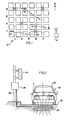
- Fig. 1 is a map of a road system upon which a fleet of vehicles operates.
- the road system is shown as including four east-west roads I, II, III and IV and five north-south roads I, II, III, IV and V.
- three fleet vehicles 12, 14 and 16 are travelling along the road system.
- a central station 18 keeps track of the location of the various fleet vehicles, and dispatches the vehicles on various errands as necessary.
- Automatic vehicle locating systems usually provide plural transmitting stations disposed at fixed locations in the area serviced by the vehicles. Each transmitter transmits a signal defining the location at which that transmitter is disposed. As the vehicle passes the transmitter, it receives the location information and retransmits it via a radio carried in the vehicle to a central location such as 18. In the map of Fig. 1, four such transmitter stations are represented at A, B, C and D.
- the location-identifying signals are communicated to the vehicle by means of a modulated magnetic field, formed by modifying a conventional traffic detector station of the type including an inductive loop embedded in the roadway.
- Fig. 2 is a schematic view of a street intersection, generally showing the elements of an inductive loop traffic detection system.
- an inductive loop 20 is embedded in a roadway 22 below the portion of the roadway over which the vehicles are expected to pass.
- the two ends of the inductive loop 20 are coupled to respective inputs of a traffic detector circuit, located within a box 24 mounted on a support pole 26.
- the coil 20 represents part of a tuned oscillator operating at a frequency in the range of, for example, 100-400 kHz.
- U.S. Patent No. 3,868,626 discloses one form which the traffic detector circuitry has taken in the past.
- the control circuit located within the box 24 energizes the inductive coil 20 such that a magnetic field is established above the roadway.
- the magnetic field is indicated in Fig. 2 by the dotted lines 28, which trace magnetic flux paths through the inductive coil 20.
- the circuitry located within the box 24 detects the shifts in the oscillations (either in their amplitude, frequency, or phase) caused by the change in magnetic permeability in the vicinity of coil 20, and then decides based upon these changes whether or not a vehicle has stopped above or passed over the inductive coil 20.
- This circuitry may include control elements for controlling an adjacent traffic light 32, or perhaps several traffic lights in the vicinity.
- the inductive loop traffic detection apparatus shown in Fig. 2 can readily be modified so as to provide an inexpensive and reliable method of communicating location-identifying information to vehicles passing over the inductive loop. Generally, this is accomplished by modulating a carrier signal in accordance with a coded signal identifying the location at which the traffic detection circuitry is disposed, and by then adding the modulated carrier into the oscillating signal used to energize the inductive loop 20. The effect of this is to provide a modulated magnetic field component which can be detected by suitable receiving equipment on vehicles passing over the inductive loop.
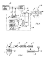
- Fig. 3 illustrates the traffic detection circuitry of Fig. 2, modified in order to add the location-identifying information into the magnetic field established around the inductive loop 20.
- the inductive loop 20 is shown connected to the output of a traffic light control circuit 34, which may have any conventional form.
- traffic light control circuit 34 is mounted within the box 24, which is conventionally large enough that additional space is available in it for mounting other components.
- the traffic light control circuit 34 will usually be powered from a conventional commercial AC power source 36.
- an additional circuit 38 is added to the components described above.
- the circuitry 38 will be housed within an enclosure suitable for mounting within the box 24 of F ig. 2.
- the circuitry 38 has only four leads, whereby its connection into the existing circuitry is readily accomplished.
- Two of the lines 40 and 42 are used to connect the power source 36 to the power supply 44 which powers the circuitry 38.
- the power supply 44 includes suitable rectification and filtering components such that the AC signal appearing across the lines 40 and 42 is converted into one or more DC power supply signals for powering the remainder of the circuitry 38.
- the interconnections between the power supply 44 and the remainder of the circuitry 38 are not shown in Fig. 3.
- the circuitry 38 also includes a carrier source 46 which provides a carrier signal upon which the location-identifying coded signal is to be modulated.
- This carrier source may, for example, provide an AC signal having a frequency of 29 kHz. The frequency of the carrier signal will be selected such that it does not interfere with the operation of the traffic light control circuit 34.
- the carrier signal provided by carrier source 46 is amplitude modulated by a frequency-shift-keyed (FSK) signal generated by a circuit 48.
- FSK signal provided at the output of the generator 48 is modulated by a binary signal coded so as to contain information representative of the street location of the inductive loop 20 with which the circuitry 38 is intended to be associated.
- This identification (ID) code will preferably be provided by a code circuit 50 which can be readily adjusted or changed, such that the circuit 38 can be made to contain a selected one of many different ID codes.
- the ID code generator 50 may be a read-only memory (ROM) having the ID code stored therein, or may merely comprise a series of microswitches, a number of jumper wires, etc.
- the ID code may represent a serial number, in which case the central station 18 will contain a chart or look-up table correlating the serial number with a particular street address. Preferably, however, the code will be an actual address, either street address or latitude/longitude, represented in ASCII code.
- the output of the ID code circuit 50 is a multibit binary word representative of the location at which the circuitry 38 will be installed.
- the identifying code is provided in parallel to the coded FSK generator 48, which provides an FSK signal at its output serially modulated by the individual bits of the ID code provided by circuit 50.
- the FSK signal is continuously and repeatedly modulated by the ID code.
- each bit of the ID code controls the frequency of the output signal provided by FSK generator 48 in a corresponding periodic time slot. If the bit has a logic value of "1", then the output frequency will be, for example, 2100 Hz in the corresponding time slot. If, on the other hand, the logic value of that bit is "0", then the frequency of the signal in the corresponding time slot will be different, for example, 1300 Hz.
- the FSK signal will be modulated at, e.g., 1200 baud.
- the FSK signal provided at the output of the FSK generator 48 is provided to an amplitude modulator circuit 52, which amplitude modulates the carrier signal provided by carrier source 46 in accordance with the FSK signal.
- the resulting modulated carrier signal is continuously provided along an output line 54 to a transformer 56.
- the transformer 56 is used to couple the modulated carrier signal provided along the output line 54 into the inductive loop 20.
- the output signal provided along the output line 54 is applied across the primary winding 58 of the transformer 56, whereas the secondary winding 60 is connected in series with the inductive coil 20.
- the transformer 56 may be a standard 24/24 turn transformer.
- the interconnection of the secondary winding 60 of transformer 56 with the inductive coil 20 may be readily accomplished by breaking one of the leads to the inductive loop 20 (indicated at 62 in Fig. 3), and connecting each end 64 and 66 of the secondary winding 60 to a corresponding one of the resulting two leads.
- the interconnection of the transformer 56 with the inductive loop 20 does not influence the operation of the traffic detection and control circuitry, since the modulated carrier signal provided along the output line 54 is selected to lie within a different frequency range than the oscillating signal used by the traffic light control circuit 34, and since the secondary winding 60 of the transformer 56 has a low impedance relative to other impedances within the circuit. Furthermore, the traffic control circuit 34 will automatically compensate for whatever impedance shift the secondary winding may introduce. Traffic control circuits are designed to be self-balancing in this respect so as to compensate for the effects which rainstorms, nearby parked cars, etc., have on the operation of the circuit.
- the effect of coupling the transformer 56 into the circuit of the inductive loop 20 is to add the modulated carrier signal to the excitation signal normally being applied across the inductive loop 20.
- the magnetic field established about the inductive loop 20 then includes a modulated component at the frequency of the carrier source 46, where that component is modulated in accordance with the FSK signal carrying the location-identifying code.
- the vehicles which participate in the location monitoring system include suitable apparatus for detecting the modulated magnetic fields established by the inductive loops 20 at the various traffic detection stations which have been modified as shown in Fig. 3.
- One embodiment of circuitry suitable for this purpose is shown in Fig. 4.
- the circuitry to be associated with a participating vehicle includes an inductive loop 70 to be mounted on the under carriage of the vehicle in a generally horizontal orientation. When thus mounted, the axis of inductive loop 70 will be aligned parallel to the magnetic axis of the inductive coil 20 embedded in the roadway when the vehicle passes over the coil 20.
- the magnetic flux passing through the inductive coil 20 then also passes through the inductive coil 70 associated with the vehicle, whereby an electrical signal is induced across the coil which corresponds to the signal applied across the inductive loop 20.
- the induced signal is amplified by a tuned amplifier 72 which has a frequency-dependent characteristic such that it selectively responds to the frequency component upon which the location-identifying information is modulated.
- This frequency component is provided to a detector and decoder circuit 74 which amplitude detects that frequency component so as to thereby derive an FSK signal corresponding to the FSK signal provided at the output of coded FSK generator 48 (Fig. 3).
- the FSK signal is applied to a decoder circuit 76, which recovers the ID code from the FSK signal.
- the resulting ID code corresponds to the ID code provided by circuit 50 of Fig. 3.
- the ID code thus recovered is thereafter automatically transmitted to the central station 18 (Fig. 1) via a transceiver 78.
- the transceiver modulates an RF carrier signal in accordance with the location ID code and a vehicle ID code unique to that vehicle.
- the modulated RF carrier signal is applied to an antenna 80 for transmission to the central station 18.
- the circuitry for automatically communicating the location-identifying code to a central location 18 by means of a radio transmission is well known in the art, and will therefore not be described in detail herein.
Abstract
Description
- The present invention relates to a method and apparatus for automatically identifying the location of a vehicle.
- Various systems are known in the art for automatically locating a plurality of fleet vehicles, such as taxi cabs, police cruisers, etc. over the relatively large area serviced by the fleet of vehicles. In a system described in the patent to Chisolm, U.S. Patent No. 3,419,865, the location of each vehicle is determined by triangulating its location with distance information obtained by reception of its radio signal by plural spaced receivers. Other systems, however, include a plurality of wayside stations distributed throughout the service area, where each station automatically communicates a location-identifying signal to vehicles passing nearby. Each vehicle automatically retransmits the location-identifying signal to a central station. The central station then logs that vehicle as being at the identified location at that time.
- One of the difficulties with the latter type of system resides in the cost and reliability of the short range communication links between each wayside station and nearby vehicles. Often, the wayside stations communicate the location-identifying signals to the passing vehicles by means of short range radio transmitters. Patents disclosing systems of this sort include Haemmig, U.S. Patent No. 4,083,003 and Ross et al., U.S. Patent No. 3,757,290. In another system, disclosed in Christ, U.S. Patent No. 3,697,941, the location-identifying information is communicated to the vehicles by means of modulated light energy.
- The present invention provides an inexpensive and reliable system for communicating location-identifying information to vehicles. In the system, information is communicated to the vehicles via existing inductive loops embedded in the roadway. Inductive loops such as this are widely used for the detection of traffic, either for statistical traffic pattern analysis or for control of one or more traffic lights in the vicinity.
- In accordance with the present invention, means is provided for generating a carrier signal modulated with a location-identifying signal identifying the location of the corresponding one of the inductive loops. Means is also included which is adapted to add the modulated carrier signal to the signal which is normally being applied to the existing inductive loop embedded in the roadway. The inductive loop thereby creates a magnetic .field above the roadway which is modulated in accordance with the location-identifying signal.
- The vehicle whose location is to be monitored includes means for detecting and demodulating this modulated magnetic field whenever the vehicle is passing over the inductive loop. Usually, the vehicle will also include some means for transmitting the location-identifying signal thus detected and demodulated back to a central location.
- The foregoing and other objects and advantages of the present invention will become more readily apparent from the following detailed description, as taken in conjunction with the accompanying drawings, wherein:
- Fig. 1 is a street map useful in understanding the general aspects of the vehicle locating system in accordance with the present invention;
- Fig. 2 is a schematic representation of the major features of a conventional traffic detection system using an inductive loop embedded in the roadway;
- Fig. 3 is a block diagram of the location-identifying signal transmitter in accordance with the teachings of the present invention; and
- Fig. 4 is a block diagram of one embodiment of the receiving circuitry to be associated with the vehicle whose location is to be monitored.
- Fig. 1 is a map of a road system upon which a fleet of vehicles operates. In Fig. 1, the road system is shown as including four east-west roads I, II, III and IV and five north-south roads I, II, III, IV and V. In the Fig. 1 map, three
fleet vehicles central station 18 keeps track of the location of the various fleet vehicles, and dispatches the vehicles on various errands as necessary. - In many systems the process of keeping track of the location of fleet vehicles is handled entirely manually. In these systems the vehicle operators are relied upon to periodically advise the
central station 18 of their location by appropriate radio communications. In other systems, however, the process of communicating vehicle location information from the vehicles to the central station is accomplished automatically so as to relieve the motor vehicle operator of the burden of repeatedly communicating the vehicle location to the central station. - Automatic vehicle locating systems usually provide plural transmitting stations disposed at fixed locations in the area serviced by the vehicles. Each transmitter transmits a signal defining the location at which that transmitter is disposed. As the vehicle passes the transmitter, it receives the location information and retransmits it via a radio carried in the vehicle to a central location such as 18. In the map of Fig. 1, four such transmitter stations are represented at A, B, C and D.
- As mentioned previously, the manner in which the location-identifying signal is transmitted to nearby vehicles from the various fixed stations differs from system to system. Each of the prior techniques has associated disadvantages, and it would be desirable if some other method could be provided for communicating the location-identifying coded signals to the vehicles.
- In accordance with the present invention, the location-identifying signals are communicated to the vehicle by means of a modulated magnetic field, formed by modifying a conventional traffic detector station of the type including an inductive loop embedded in the roadway.
- Fig. 2 is a schematic view of a street intersection, generally showing the elements of an inductive loop traffic detection system. As shown in Fig. 2, an
inductive loop 20 is embedded in aroadway 22 below the portion of the roadway over which the vehicles are expected to pass. The two ends of theinductive loop 20 are coupled to respective inputs of a traffic detector circuit, located within abox 24 mounted on asupport pole 26. Thecoil 20 represents part of a tuned oscillator operating at a frequency in the range of, for example, 100-400 kHz. U.S. Patent No. 3,868,626 discloses one form which the traffic detector circuitry has taken in the past. The control circuit located within thebox 24 energizes theinductive coil 20 such that a magnetic field is established above the roadway. The magnetic field is indicated in Fig. 2 by thedotted lines 28, which trace magnetic flux paths through theinductive coil 20. - When a vehicle 30 passes over the
inductive loop 20, it has the effect of changing the magnetic permeability along the flux paths through theinductive coil 20, thereby influencing the oscillating electric signal which energizes the inductive coil. The circuitry located within thebox 24 detects the shifts in the oscillations (either in their amplitude, frequency, or phase) caused by the change in magnetic permeability in the vicinity ofcoil 20, and then decides based upon these changes whether or not a vehicle has stopped above or passed over theinductive coil 20. This circuitry may include control elements for controlling an adjacent traffic light 32, or perhaps several traffic lights in the vicinity. - The inductive loop traffic detection apparatus shown in Fig. 2 can readily be modified so as to provide an inexpensive and reliable method of communicating location-identifying information to vehicles passing over the inductive loop. Generally, this is accomplished by modulating a carrier signal in accordance with a coded signal identifying the location at which the traffic detection circuitry is disposed, and by then adding the modulated carrier into the oscillating signal used to energize the
inductive loop 20. The effect of this is to provide a modulated magnetic field component which can be detected by suitable receiving equipment on vehicles passing over the inductive loop. - Fig. 3 illustrates the traffic detection circuitry of Fig. 2, modified in order to add the location-identifying information into the magnetic field established around the
inductive loop 20. In Fig. 3, theinductive loop 20 is shown connected to the output of a trafficlight control circuit 34, which may have any conventional form. Many types of traffic light control circuits are presently in use, and it is contemplated that the invention can be utilized in conjunction with any of these. The trafficlight control circuit 34 is mounted within thebox 24, which is conventionally large enough that additional space is available in it for mounting other components. The trafficlight control circuit 34 will usually be powered from a conventional commercialAC power source 36. - In accordance with the present invention, an additional circuit 38 is added to the components described above. Preferably, the circuitry 38 will be housed within an enclosure suitable for mounting within the
box 24 of Fig. 2. As shown in Fig. 3, the circuitry 38 has only four leads, whereby its connection into the existing circuitry is readily accomplished. Two of thelines 40 and 42 are used to connect thepower source 36 to thepower supply 44 which powers the circuitry 38. Thepower supply 44 includes suitable rectification and filtering components such that the AC signal appearing across thelines 40 and 42 is converted into one or more DC power supply signals for powering the remainder of the circuitry 38. For simplicity of illustration, the interconnections between thepower supply 44 and the remainder of the circuitry 38 are not shown in Fig. 3. - The circuitry 38 also includes a
carrier source 46 which provides a carrier signal upon which the location-identifying coded signal is to be modulated. This carrier source may, for example, provide an AC signal having a frequency of 29 kHz. The frequency of the carrier signal will be selected such that it does not interfere with the operation of the trafficlight control circuit 34. In Fig. 3, the carrier signal provided bycarrier source 46 is amplitude modulated by a frequency-shift-keyed (FSK) signal generated by acircuit 48. The FSK signal provided at the output of thegenerator 48 is modulated by a binary signal coded so as to contain information representative of the street location of theinductive loop 20 with which the circuitry 38 is intended to be associated. This identification (ID) code will preferably be provided by acode circuit 50 which can be readily adjusted or changed, such that the circuit 38 can be made to contain a selected one of many different ID codes. TheID code generator 50 may be a read-only memory (ROM) having the ID code stored therein, or may merely comprise a series of microswitches, a number of jumper wires, etc. The ID code may represent a serial number, in which case thecentral station 18 will contain a chart or look-up table correlating the serial number with a particular street address. Preferably, however, the code will be an actual address, either street address or latitude/longitude, represented in ASCII code. - The output of the
ID code circuit 50 is a multibit binary word representative of the location at which the circuitry 38 will be installed. The identifying code is provided in parallel to the codedFSK generator 48, which provides an FSK signal at its output serially modulated by the individual bits of the ID code provided bycircuit 50. The FSK signal is continuously and repeatedly modulated by the ID code. Thus, each bit of the ID code controls the frequency of the output signal provided byFSK generator 48 in a corresponding periodic time slot. If the bit has a logic value of "1", then the output frequency will be, for example, 2100 Hz in the corresponding time slot. If, on the other hand, the logic value of that bit is "0", then the frequency of the signal in the corresponding time slot will be different, for example, 1300 Hz. The FSK signal will be modulated at, e.g., 1200 baud. - The FSK signal provided at the output of the
FSK generator 48 is provided to anamplitude modulator circuit 52, which amplitude modulates the carrier signal provided bycarrier source 46 in accordance with the FSK signal. The resulting modulated carrier signal is continuously provided along anoutput line 54 to atransformer 56. - The
transformer 56 is used to couple the modulated carrier signal provided along theoutput line 54 into theinductive loop 20. The output signal provided along theoutput line 54 is applied across the primary winding 58 of thetransformer 56, whereas the secondary winding 60 is connected in series with theinductive coil 20. Thetransformer 56 may be a standard 24/24 turn transformer. The interconnection of the secondary winding 60 oftransformer 56 with theinductive coil 20 may be readily accomplished by breaking one of the leads to the inductive loop 20 (indicated at 62 in Fig. 3), and connecting eachend - The interconnection of the
transformer 56 with theinductive loop 20 does not influence the operation of the traffic detection and control circuitry, since the modulated carrier signal provided along theoutput line 54 is selected to lie within a different frequency range than the oscillating signal used by the trafficlight control circuit 34, and since the secondary winding 60 of thetransformer 56 has a low impedance relative to other impedances within the circuit. Furthermore, thetraffic control circuit 34 will automatically compensate for whatever impedance shift the secondary winding may introduce. Traffic control circuits are designed to be self-balancing in this respect so as to compensate for the effects which rainstorms, nearby parked cars, etc., have on the operation of the circuit. - The effect of coupling the
transformer 56 into the circuit of theinductive loop 20 is to add the modulated carrier signal to the excitation signal normally being applied across theinductive loop 20. Thus, the magnetic field established about theinductive loop 20 then includes a modulated component at the frequency of thecarrier source 46, where that component is modulated in accordance with the FSK signal carrying the location-identifying code. - The vehicles which participate in the location monitoring system include suitable apparatus for detecting the modulated magnetic fields established by the
inductive loops 20 at the various traffic detection stations which have been modified as shown in Fig. 3. One embodiment of circuitry suitable for this purpose is shown in Fig. 4. As shown in Fig. 4, the circuitry to be associated with a participating vehicle includes an inductive loop 70 to be mounted on the under carriage of the vehicle in a generally horizontal orientation. When thus mounted, the axis of inductive loop 70 will be aligned parallel to the magnetic axis of theinductive coil 20 embedded in the roadway when the vehicle passes over thecoil 20. The magnetic flux passing through theinductive coil 20 then also passes through the inductive coil 70 associated with the vehicle, whereby an electrical signal is induced across the coil which corresponds to the signal applied across theinductive loop 20. - The induced signal is amplified by a
tuned amplifier 72 which has a frequency-dependent characteristic such that it selectively responds to the frequency component upon which the location-identifying information is modulated. This frequency component is provided to a detector anddecoder circuit 74 which amplitude detects that frequency component so as to thereby derive an FSK signal corresponding to the FSK signal provided at the output of coded FSK generator 48 (Fig. 3). The FSK signal is applied to adecoder circuit 76, which recovers the ID code from the FSK signal. The resulting ID code corresponds to the ID code provided bycircuit 50 of Fig. 3. - The ID code thus recovered is thereafter automatically transmitted to the central station 18 (Fig. 1) via a
transceiver 78. The transceiver modulates an RF carrier signal in accordance with the location ID code and a vehicle ID code unique to that vehicle. The modulated RF carrier signal is applied to anantenna 80 for transmission to thecentral station 18. The circuitry for automatically communicating the location-identifying code to acentral location 18 by means of a radio transmission is well known in the art, and will therefore not be described in detail herein. - Although the invention has been described with respect to a preferred embodiment, it will be appreciated that various rearrangements and alterations of parts may be made without departing from the spirit and scope of the present invention, as defined in the appended claims.
Claims (14)
Applications Claiming Priority (2)
| Application Number | Priority Date | Filing Date | Title |
|---|---|---|---|
| US06/384,614 US4529982A (en) | 1982-06-03 | 1982-06-03 | Vehicle locating system |
| US384614 | 1989-07-25 |
Publications (2)
| Publication Number | Publication Date |
|---|---|
| EP0096252A2 true EP0096252A2 (en) | 1983-12-21 |
| EP0096252A3 EP0096252A3 (en) | 1987-05-20 |
Family
ID=23518027
Family Applications (1)
| Application Number | Title | Priority Date | Filing Date |
|---|---|---|---|
| EP83104906A Withdrawn EP0096252A3 (en) | 1982-06-03 | 1983-05-18 | Vehicle location system |
Country Status (8)
| Country | Link |
|---|---|
| US (1) | US4529982A (en) |
| EP (1) | EP0096252A3 (en) |
| JP (1) | JPS5947700A (en) |
| AU (1) | AU1522283A (en) |
| CA (1) | CA1199711A (en) |
| DK (1) | DK244183A (en) |
| FI (1) | FI831888L (en) |
| NO (1) | NO831988L (en) |
Cited By (13)
| Publication number | Priority date | Publication date | Assignee | Title |
|---|---|---|---|---|
| EP0155108A2 (en) * | 1984-02-24 | 1985-09-18 | Troll Detector Systems Limited | Detection system |
| EP0199342A2 (en) * | 1985-04-22 | 1986-10-29 | Omron Tateisi Electronics Co. | Vehicle detecting method and system which can communicate with vehicles |
| EP0290161A2 (en) * | 1987-05-08 | 1988-11-09 | Detector Systems Inc. | Vehicle communication system using roadway loops |
| US4996716A (en) * | 1987-12-28 | 1991-02-26 | Detector Systems, Inc. | Vehicle communication system using existing roadway loops |
| US5089815A (en) * | 1987-05-08 | 1992-02-18 | Detector Systems, Inc. | Vehicle communication system using existing roadway loops |
| US9551788B2 (en) | 2015-03-24 | 2017-01-24 | Jim Epler | Fleet pan to provide measurement and location of a stored transport item while maximizing space in an interior cavity of a trailer |
| US9779449B2 (en) | 2013-08-30 | 2017-10-03 | Spireon, Inc. | Veracity determination through comparison of a geospatial location of a vehicle with a provided data |
| US9779379B2 (en) | 2012-11-05 | 2017-10-03 | Spireon, Inc. | Container verification through an electrical receptacle and plug associated with a container and a transport vehicle of an intermodal freight transport system |
| US10169822B2 (en) | 2011-12-02 | 2019-01-01 | Spireon, Inc. | Insurance rate optimization through driver behavior monitoring |
| US10223744B2 (en) | 2013-12-31 | 2019-03-05 | Spireon, Inc. | Location and event capture circuitry to facilitate remote vehicle location predictive modeling when global positioning is unavailable |
| US10255824B2 (en) | 2011-12-02 | 2019-04-09 | Spireon, Inc. | Geospatial data based assessment of driver behavior |
| US11299219B2 (en) | 2018-08-20 | 2022-04-12 | Spireon, Inc. | Distributed volumetric cargo sensor system |
| US11475680B2 (en) | 2018-12-12 | 2022-10-18 | Spireon, Inc. | Cargo sensor system implemented using neural network |
Families Citing this family (29)
| Publication number | Priority date | Publication date | Assignee | Title |
|---|---|---|---|---|
| US5245335A (en) * | 1984-03-06 | 1993-09-14 | Comsource Systems Corp. | Transceiver system for communication over wire laid along the path of guided/vehicles |
| US5198811A (en) * | 1987-05-08 | 1993-03-30 | Detector Systems, Inc. | Vehicle communication system using existing roadway loops wherein the physical integrity of the loop is kept intact |
| US4973952A (en) * | 1987-09-21 | 1990-11-27 | Information Resources, Inc. | Shopping cart display system |
| DE3828725A1 (en) * | 1987-09-29 | 1989-04-13 | Pioneer Electronic Corp | METHOD FOR RECORDING THE DRIVING ROUTE DATA FOR A NAVIGATION DEVICE OF A MOTOR VEHICLE |
| US5057831A (en) * | 1990-05-29 | 1991-10-15 | Signalmatic International, Inc. | Vehicle simulation circuit for loop traffic signal control system |
| US5455768A (en) * | 1992-11-06 | 1995-10-03 | Safetran Traffic Systems, Inc. | System for determining vehicle speed and presence |
| US5652577A (en) * | 1994-10-27 | 1997-07-29 | Frasier Products, Inc. | Device and method for passively activating inductive loop sensor |
| US5757288A (en) * | 1996-05-02 | 1998-05-26 | Mitron Systems Corporation | Vehicle detector system and method |
| US5900825A (en) * | 1996-08-01 | 1999-05-04 | Manitto Technologies, Inc. | System and method for communicating location and direction specific information to a vehicle |
| GB2348501B (en) | 1999-03-31 | 2003-07-30 | Diamond Consulting Services Lt | Loop sensing apparatus for traffic detection |
| US6337640B2 (en) * | 1999-03-31 | 2002-01-08 | Diamond Consulting Services Limited | Inductive loop sensor for traffic detection, and traffic monitoring apparatus and method using such a loop sensor |
| EP1250691B1 (en) * | 1999-12-15 | 2006-05-17 | Vert, Inc. | System and method for managing advertisement and information displays on vehicles based on an e-commerce site |
| US6505123B1 (en) | 2000-07-24 | 2003-01-07 | Weatherbank, Inc. | Interactive weather advisory system |
| US6720888B2 (en) | 2000-09-07 | 2004-04-13 | Savi Technology, Inc. | Method and apparatus for tracking mobile devices using tags |
| US6940392B2 (en) * | 2001-04-24 | 2005-09-06 | Savi Technology, Inc. | Method and apparatus for varying signals transmitted by a tag |
| US6542114B1 (en) * | 2000-09-07 | 2003-04-01 | Savi Technology, Inc. | Method and apparatus for tracking items using dual frequency tags |
| US6765484B2 (en) | 2000-09-07 | 2004-07-20 | Savi Technology, Inc. | Method and apparatus for supplying commands to a tag |
| US6747558B1 (en) | 2001-11-09 | 2004-06-08 | Savi Technology, Inc. | Method and apparatus for providing container security with a tag |
| US7198227B2 (en) * | 2004-06-10 | 2007-04-03 | Goodrich Corporation | Aircraft cargo locating system |
| US20060071791A1 (en) * | 2004-09-29 | 2006-04-06 | Honeywell International Inc. | Enhanced RFID vehicle presence detection system |
| US20060161469A1 (en) | 2005-01-14 | 2006-07-20 | Weatherbank, Inc. | Interactive advisory system |
| US8832121B2 (en) * | 2005-02-02 | 2014-09-09 | Accuweather, Inc. | Location-based data communications system and method |
| US8229467B2 (en) | 2006-01-19 | 2012-07-24 | Locator IP, L.P. | Interactive advisory system |
| US8634814B2 (en) | 2007-02-23 | 2014-01-21 | Locator IP, L.P. | Interactive advisory system for prioritizing content |
| US20090045675A1 (en) * | 2007-08-14 | 2009-02-19 | Novak Gerald J | Vehicle Theft Prevention Apparatus and Method Utilizing a Transmission Signal |
| US9123238B1 (en) * | 2013-05-17 | 2015-09-01 | Michael Gordon Smith | Method to enable small vehicles to trip a traffic light inductive loop sensor |
| DE102017215932B3 (en) | 2017-09-11 | 2019-02-28 | Audi Ag | Method for determining position information of a motor vehicle and motor vehicle |
| DE102018129800A1 (en) * | 2018-11-26 | 2020-05-28 | Bayerische Motoren Werke Aktiengesellschaft | System and method for determining a position of a motor vehicle in free traffic |
| CN109887269A (en) * | 2019-03-28 | 2019-06-14 | 中航物业管理有限公司 | A kind of taxi two times scheduling system and method |
Citations (4)
| Publication number | Priority date | Publication date | Assignee | Title |
|---|---|---|---|---|
| DE2325935A1 (en) * | 1973-05-15 | 1974-12-05 | Huber Signalbau Muenchen | PROCEDURE AND ARRANGEMENT FOR DETECTING VEHICLES IN TRAFFIC FLOWS |
| US3996555A (en) * | 1974-09-17 | 1976-12-07 | The Secretary Of State For The Environment In Her Britannic Majesty's Government Of The United Kingdom Of Great Britain And Northern Ireland | Identification of vehicles |
| GB1543910A (en) * | 1976-04-20 | 1979-04-11 | Plessey Co Ltd | Vehicle communication systems |
| US4251797A (en) * | 1976-07-14 | 1981-02-17 | Robert Bosch Gmbh | Vehicular direction guidance system, particularly for interchange of information between road mounted units and vehicle mounted equipment |
Family Cites Families (7)
| Publication number | Priority date | Publication date | Assignee | Title |
|---|---|---|---|---|
| US3419865A (en) * | 1967-05-10 | 1968-12-31 | John P. Chisholm | Mobile emergency unit locating system |
| US3757290A (en) * | 1971-03-12 | 1973-09-04 | Sperry Rand Corp | Automatic vehicle monitoring system |
| US3697941A (en) * | 1971-07-01 | 1972-10-10 | Devenco Inc | Vehicle location system and method |
| US3868626A (en) * | 1973-07-09 | 1975-02-25 | Gulf & Western Industries | Digital loop detector system |
| US4083003A (en) * | 1973-11-05 | 1978-04-04 | Products Of Information Technology, Inc. | Vehicle location system |
| US4083008A (en) * | 1975-04-10 | 1978-04-04 | Blaupunkt-Werke Gmbh | Method and circuit for generation of digitally frequency-shiftable electric signals |
| US4253192A (en) * | 1979-02-05 | 1981-02-24 | The United States Of America As Represented By The Secretary Of The Army | Telemetric system |
-
1982
- 1982-06-03 US US06/384,614 patent/US4529982A/en not_active Expired - Fee Related
-
1983
- 1983-05-18 EP EP83104906A patent/EP0096252A3/en not_active Withdrawn
- 1983-05-26 FI FI831888A patent/FI831888L/en not_active Application Discontinuation
- 1983-05-31 AU AU15222/83A patent/AU1522283A/en not_active Abandoned
- 1983-05-31 DK DK244183A patent/DK244183A/en not_active Application Discontinuation
- 1983-06-02 JP JP58098731A patent/JPS5947700A/en active Pending
- 1983-06-02 CA CA000429491A patent/CA1199711A/en not_active Expired
- 1983-06-02 NO NO831988A patent/NO831988L/en unknown
Patent Citations (4)
| Publication number | Priority date | Publication date | Assignee | Title |
|---|---|---|---|---|
| DE2325935A1 (en) * | 1973-05-15 | 1974-12-05 | Huber Signalbau Muenchen | PROCEDURE AND ARRANGEMENT FOR DETECTING VEHICLES IN TRAFFIC FLOWS |
| US3996555A (en) * | 1974-09-17 | 1976-12-07 | The Secretary Of State For The Environment In Her Britannic Majesty's Government Of The United Kingdom Of Great Britain And Northern Ireland | Identification of vehicles |
| GB1543910A (en) * | 1976-04-20 | 1979-04-11 | Plessey Co Ltd | Vehicle communication systems |
| US4251797A (en) * | 1976-07-14 | 1981-02-17 | Robert Bosch Gmbh | Vehicular direction guidance system, particularly for interchange of information between road mounted units and vehicle mounted equipment |
Cited By (16)
| Publication number | Priority date | Publication date | Assignee | Title |
|---|---|---|---|---|
| EP0155108A2 (en) * | 1984-02-24 | 1985-09-18 | Troll Detector Systems Limited | Detection system |
| EP0155108A3 (en) * | 1984-02-24 | 1987-12-02 | Troll Detector Systems Limited | Detection system |
| EP0199342A2 (en) * | 1985-04-22 | 1986-10-29 | Omron Tateisi Electronics Co. | Vehicle detecting method and system which can communicate with vehicles |
| EP0199342A3 (en) * | 1985-04-22 | 1989-03-29 | Omron Tateisi Electronics Co. | Vehicle detecting method and system which can communicate with vehicles |
| EP0290161A2 (en) * | 1987-05-08 | 1988-11-09 | Detector Systems Inc. | Vehicle communication system using roadway loops |
| EP0290161A3 (en) * | 1987-05-08 | 1989-06-28 | Detector Systems Inc. | Vehicle communication system using roadway loops |
| US5089815A (en) * | 1987-05-08 | 1992-02-18 | Detector Systems, Inc. | Vehicle communication system using existing roadway loops |
| US4996716A (en) * | 1987-12-28 | 1991-02-26 | Detector Systems, Inc. | Vehicle communication system using existing roadway loops |
| US10255824B2 (en) | 2011-12-02 | 2019-04-09 | Spireon, Inc. | Geospatial data based assessment of driver behavior |
| US10169822B2 (en) | 2011-12-02 | 2019-01-01 | Spireon, Inc. | Insurance rate optimization through driver behavior monitoring |
| US9779379B2 (en) | 2012-11-05 | 2017-10-03 | Spireon, Inc. | Container verification through an electrical receptacle and plug associated with a container and a transport vehicle of an intermodal freight transport system |
| US9779449B2 (en) | 2013-08-30 | 2017-10-03 | Spireon, Inc. | Veracity determination through comparison of a geospatial location of a vehicle with a provided data |
| US10223744B2 (en) | 2013-12-31 | 2019-03-05 | Spireon, Inc. | Location and event capture circuitry to facilitate remote vehicle location predictive modeling when global positioning is unavailable |
| US9551788B2 (en) | 2015-03-24 | 2017-01-24 | Jim Epler | Fleet pan to provide measurement and location of a stored transport item while maximizing space in an interior cavity of a trailer |
| US11299219B2 (en) | 2018-08-20 | 2022-04-12 | Spireon, Inc. | Distributed volumetric cargo sensor system |
| US11475680B2 (en) | 2018-12-12 | 2022-10-18 | Spireon, Inc. | Cargo sensor system implemented using neural network |
Also Published As
| Publication number | Publication date |
|---|---|
| FI831888L (en) | 1983-12-04 |
| NO831988L (en) | 1983-12-05 |
| JPS5947700A (en) | 1984-03-17 |
| FI831888A0 (en) | 1983-05-26 |
| DK244183A (en) | 1983-12-04 |
| EP0096252A3 (en) | 1987-05-20 |
| US4529982A (en) | 1985-07-16 |
| AU1522283A (en) | 1983-12-08 |
| DK244183D0 (en) | 1983-05-31 |
| CA1199711A (en) | 1986-01-21 |
Similar Documents
| Publication | Publication Date | Title |
|---|---|---|
| US4529982A (en) | Vehicle locating system | |
| US5867801A (en) | Remote asset monitoring system | |
| US5032845A (en) | Vehicle locating system with Loran-C | |
| US4296400A (en) | Installation for control of a traffic light system by vehicles having an automatic location determination | |
| MXPA98004362A (en) | Traffic information warning system. | |
| US8294555B2 (en) | Communication system for inductive power transfer system | |
| US4487385A (en) | Method of controlling a railroad car in automatic drive | |
| US4920340A (en) | Vehicle detecting method and system which can communicate with vehicles | |
| NO875244L (en) | PROCEDURE FOR DISPOSING OF AUTOMATIC TRAFFIC INFORMATION, AND DEVICE FOR EXECUTING THE PROCEDURE. | |
| CN105059323B (en) | A kind of localization method based on Geomagnetism Information, apparatus and system | |
| EP0155108A2 (en) | Detection system | |
| JP3858506B2 (en) | In-vehicle communication device for road-to-vehicle communication | |
| KR100315581B1 (en) | Traffic information collection method and device | |
| JPS5922638Y2 (en) | Device that controls traffic signal lighting equipment | |
| JP2653852B2 (en) | Vehicle position detection and traveling direction determination system | |
| JPH05307697A (en) | Communication equipment between road and vehicle | |
| JPH0779183A (en) | Road side beacon equipment and beacon system using the road side beacon equipment | |
| JPH05225495A (en) | On-vehicle communication equipment | |
| JPS60204099A (en) | Broad area monitoring system for automobile traffic | |
| JP2000123285A (en) | Vehicle position recognition device | |
| JP2003016580A (en) | Device and system for detecting mobile body | |
| JPS61229200A (en) | Apparatus for communication between road vehicles | |
| JP2828571B2 (en) | Point passing detection system | |
| JPH0271400A (en) | Stand-type beacon system | |
| JPS58119099A (en) | Call method for bus location system |
Legal Events
| Date | Code | Title | Description |
|---|---|---|---|
| PUAI | Public reference made under article 153(3) epc to a published international application that has entered the european phase |
Free format text: ORIGINAL CODE: 0009012 |
|
| AK | Designated contracting states |
Designated state(s): BE DE FR GB IT NL SE |
|
| PUAL | Search report despatched |
Free format text: ORIGINAL CODE: 0009013 |
|
| AK | Designated contracting states |
Kind code of ref document: A3 Designated state(s): BE DE FR GB IT NL SE |
|
| 17P | Request for examination filed |
Effective date: 19871110 |
|
| 17Q | First examination report despatched |
Effective date: 19880624 |
|
| STAA | Information on the status of an ep patent application or granted ep patent |
Free format text: STATUS: THE APPLICATION IS DEEMED TO BE WITHDRAWN |
|
| 18D | Application deemed to be withdrawn |
Effective date: 19890705 |
|
| RIN1 | Information on inventor provided before grant (corrected) |
Inventor name: KARLSTROM, KRISTER Inventor name: FABRICIUS-HANSEN, ROLF |