EP0256815A2 - Preventing data loss in computers - Google Patents
Preventing data loss in computers Download PDFInfo
- Publication number
- EP0256815A2 EP0256815A2 EP87307030A EP87307030A EP0256815A2 EP 0256815 A2 EP0256815 A2 EP 0256815A2 EP 87307030 A EP87307030 A EP 87307030A EP 87307030 A EP87307030 A EP 87307030A EP 0256815 A2 EP0256815 A2 EP 0256815A2
- Authority
- EP
- European Patent Office
- Prior art keywords
- computer
- cpu
- power supply
- ram
- main power
- Prior art date
- Legal status (The legal status is an assumption and is not a legal conclusion. Google has not performed a legal analysis and makes no representation as to the accuracy of the status listed.)
- Withdrawn
Links
Images


Classifications
-
- G—PHYSICS
- G06—COMPUTING; CALCULATING OR COUNTING
- G06F—ELECTRIC DIGITAL DATA PROCESSING
- G06F12/00—Accessing, addressing or allocating within memory systems or architectures
- G06F12/16—Protection against loss of memory contents
-
- G—PHYSICS
- G06—COMPUTING; CALCULATING OR COUNTING
- G06F—ELECTRIC DIGITAL DATA PROCESSING
- G06F1/00—Details not covered by groups G06F3/00 - G06F13/00 and G06F21/00
- G06F1/26—Power supply means, e.g. regulation thereof
- G06F1/30—Means for acting in the event of power-supply failure or interruption, e.g. power-supply fluctuations
Definitions
- UPS uninterruptible power supply
- a storage battery a battery charger, and an inverter; both the input and the output of the UPS are AC.
- AC from the power line is rectified to DC and then inverted back to AC for output to the computer.
- the AC power line is interrupted, i.e., its voltage drops below a certain minimum value, energy is drawn from the battery through the inverter.
- Devices such as those disclosed in U.S. Patents: 4,458,307; 4,327,410; 4,307,455; and 3,286,239 provide for orderly shut down and restart of microcomputer systems but are not suitable for use with higher capability, more complex computers such as the PC-AT manufactured by the International Business Machines Corporation.
- the higher capability machines execute software application programs such as word processors and spreadsheets through the mediation of software operating systems such as PC-DOS and MS-DOS developed by the MicroSoft Corporation.
- FIG. 2 shows more details of the UPS 5 and the monitor circuit 4 and their interconnection through power and signal conductors 9.
- the UPS 5 is of a type known in the prior art, comprising generally a battery charger 25 which receives AC power from the main supply through power conductors 6, a blocking device 26 such as a diode, a means 27 of supplying power when the main AC supply is interrupted or absent such as a storage battery, and an inverter 28.
- the charger 25 rectifies the input AC voltage to a DC voltage appropriate to the supply means 27; in one embodiment the supply means is a 12-volt battery therefore the output voltage of the charger 25 is appropriate to maintain the battery fully charged.
- the DC output of the charger 25 and supply means 27 is inverted back to AC by the inverter 28 and output to the computer 1 and other I/O devices 2.
- a voltage comparator 33 has, as one input, a reference voltage provided by a zener diode 34.
- the reference voltage remains constant as the output voltage of the power supply means 27 decreases due to power continuing to be supplied to the computer 1 and other I/O devices 2 when the main power supply is interrupted.
- a resistor 35 limits the amount of current flowing through the zener diode 34.
- the other input of the comparator 33 is a voltage proportional to the output voltage of the power supply means 27 which can be provided by means such as the resistive divider network 36.
- Figure 3 shows part of the interconnections between the computer 1 and auxiliary board 3.
- the computer 1 includes a central processing unit (CPU) 13 for performing calculations and executing program instructions provided by read-only memory (ROM) 15 and random-access memory (RAM) 14. These devices are linked by a data- and address-bus 21 and their operation is synchronized by a master system clock 12.
- the auxiliary board 3 includes an auxiliary ROM 19, an auxiliary RAM 20 and a large auxiliary FIFO RAM 16 which are also connected to the data- and address-bus 21. Program instructions stored in the auxiliary ROM 19 are executed by the CPU 13. The operation of the large FIFO RAM 16 is controlled by a control circuit 17 and auxiliary clock 18.
- Buffers 41 have their inputs connected to the address lines of the computer's data- and address-bus 21 and to the computer's control signals; their outputs are connected to other components on the auxiliary board 3.
- the buffers serve to isolate electrically the auxiliary board from the computer, thus avoiding possible undesirable interactions, while transmitting address information to the auxiliary board.
- Bus transceivers are connected to the data lines of the computer's data- and address-bus 21 and to other components on the auxiliary board 3. Information moves in both directions through the transceivers 42 which still help to provide electrical isolation between the auxiliary board 3 and the computer 1. Other gates and signals are provided to control the operation of the transceivers 42.
- One of the transceivers is used for the large auxiliary FIFO memory 16 while the other transceiver is used for the auxiliary ROM 19 and the auxiliary RAM 20.
- Figure 4b shows a means 43 for setting the program address of the auxiliary board 3 and for determining when that address is received on certain of the address lines from the computer.
- the board address is set by selecting the ON/OFF position of a series of switches SW1.
- the voltage levels of the address lines are compared to the voltage levels determined by the switches; when the corresponding levels match, a decoder means 44 is enabled.
- the decoder means 44 then outputs one of several control signals to the other components of the auxiliary board 3 in accordance with the values of three of the address lines and the control signals IOR and IOW.
- Figure 4d shows the large auxiliary memory 16 and its control circuits 17 and clock 18.
- the large memory 16 is an array of dynamic random access memory circuit that thus depend on a continuous supply of power to maintain their contents.
- the continuous supply of power is provided by the voltage regulator circuit 37 in monitor circuit 4.
- the capacity of the memory 16 need only be large enough to store the entire contents of the computer's volatile RAM 14 and the CPU state, together with the contents of any other boards the loss of which it is desired to have prevented. It will therefore be appreciated that the function of memory 16 can be performed by any suitable non-volatile random access memory including magnetic bubble or disk-drive types which do not require continuous power.
- the nature of the control circuit 17 and clock 18 would likewise change accordingly.
- the operation of the memory 16 and control circuit 17 is synchronized by the auxiliary clock circuit 18; these circuits are provided continuous power from the supply means 27 through the regulator 37 and thus continue to operate and maintain the contents of the memory 16 even when the main power supply is interrupted.
- the operation of the auxiliary board memory circuits is synchronized with the computer's master system clock 12 by the circuitry 48 which also ensures that there are no latch-up problems experienced by the system when the auxiliary board is installed.
- the large auxiliary memory 16 may be made available to the computer operator for use during normal operation, i.e., when the main power supply is not interrupted.
- the memory can thus be employed in the manner of a VDisk which is a designation of the operating system PC-DOS, versions 3.1 and 3.2. The memory therefore appears to be an element of the actual hardware configuration of the computer and is treated as another peripheral device.
- the large memory 16 can be made available as a RAMDisk, which is a designation of several independent software makers, or other equivalent.
- any contents that are stored in the memory must be removed and stored elsewhere before the memory is made available to compensate for a power failure. This can be provided by automatically evacuating the contents of the memory 16 to another non-volatile memory such as a hard disk drive peripheral before the contents of the computer's other RAM 14 and CPU state are stored.
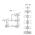
- FIG. 5a shows a flowchart of a system startup program module in accordance with the present invention.
- a program module called the Power Fail Interrupt Service Routine in loaded from the auxiliary ROM 19 into the RAM 14 and installed under the control of the operating system.
- the circuitry of the auxiliary board 3 is then reset and prepared for a power interruption by initializing or setting up the large memory 16 and enabling the interrupt signals to the CPU.
- program control returns for either continued execution of the AUTOEXEC.BAT file which is a file "non-resident" under DOS or to other programs "resident" under the operating system.
- Short power interrupts may require a time period to allow the computer's power supplies to drain properly before power should be reapplied. Also, means may be included to monitor the stability of the main power supply and prevent rebooting before a continuous period of stable main power has elapsed.
- the system can automatically provide for an orderly shutdown of the operation of the computer.
- the work-saving system can also save the contents of auxiliary circuit boards such as extended graphics adaptor boards.
Abstract
Description
- The present invention relates to computer systems that are protected against the loss of data stored in volatile memories as a result of electric power interruption.
- One method of avoiding memory loss has been the use of an uninterruptible power supply which is inserted between the computer to be protected and the AC power line. Typically, an uninterruptible power supply (UPS) consists of a storage battery, a battery charger, and an inverter; both the input and the output of the UPS are AC. Under normal conditions AC from the power line is rectified to DC and then inverted back to AC for output to the computer. When the AC power line is interrupted, i.e., its voltage drops below a certain minimum value, energy is drawn from the battery through the inverter.
- Since the UPS effectively replaces the main power supply of the power line, the entire computer system continues to function without memory loss. The high power level necessary to operate the entire computer requires a high capacity storage battery and similarly high power battery charger and inverter. Since these components are large and expensive, the use of a UPS with a smaller computer system has not been considered cost-effective.
- Reducing sufficiently the capacities of the parts of the UPS to make its cost acceptable introduces the problem of limiting the time period that the UPS can compensate for a main power interruption. The time period should be long enough to compensate for momentary or short-term power failures, but short enough to avoid excessive UPS cost. However, when the UPS battery voltage drops low enough, operation of the computer system will be disrupted in the same way as an unprotected computer. An orderly shutdown of the computer is, therefore, desirable to avoid the loss of any data that might be stored in volatile memory, i.e., memory devices which require a continuous supply of electric power to maintain their contents. An orderly shutdown of a higher capability computer includes the transfer of any data or programs from unprotected volatile memory to either a non-volatile memory or a volatile memory having a continuous power supply independent of the AC line. Once the computer has been put into a state of "suspended animation," it is particularly useful to "revive" the computer when the main power supply is restored and restart it from the condition at which it was shut down.
- Devices such as those disclosed in U.S. Patents: 4,458,307; 4,327,410; 4,307,455; and 3,286,239 provide for orderly shut down and restart of microcomputer systems but are not suitable for use with higher capability, more complex computers such as the PC-AT manufactured by the International Business Machines Corporation. The higher capability machines execute software application programs such as word processors and spreadsheets through the mediation of software operating systems such as PC-DOS and MS-DOS developed by the MicroSoft Corporation.
- Portions of the operating system and application program are stored in the computer in volatile random-access memory (RAM) for faster access during program execution. The software is executed by controlling the state of the computer's central processing unit (CPU) which includes data busses, data registers, and internal switches. The state of the CPU including pointers, vectors, wait-state, etc. is the condition of the data registers and busses and the switches at a given cycle of the CPU's master clock. An orderly shutdown of a higher capability computer requires the transfer of those portions of the application program and operating system stored in volatile RAM and information on the CPU's state to either a non-volatile memory or a continuously powered memory. Restarting the computer requires reloading of the application program and operating system into the RAM and precise resetting of the CPU state. The data saving system should also operate with any software or CPU either automatically or with minimal user interaction. These features are beyond the capability of the prior art devices.
- The present invention provides, for a digital computer having a central processing unit (CPU) driven by an operating system environment external to the CPU and volatile random-access memory (RAM), a system for preventing an unintentional loss due to an interruption of a main power supply of the computer's application program and operating system stored in RAM and the CPU's state, comprising:
means for supplying electric power to the computer after a main power interruption;
means for monitoring the main electric power supply and for generating a signal indicative of an interruption thereof;
means for directing an operation of the computer and for conserving power to be supplied by the power supply means, the directing means being responsive to the interruption signal and including an interrupt program stored in a non-volatile memory; and
means for storing the application program and operating system stored in the RAM and the CPU's state, the storing means being responsive to the directing means. - The present invention further provides, for a digital computer having a central processing unit (CPU) driven by an operating system environment external to the CPU and volatile random-access memory (RAM), a system for preventing an unintentional loss due to an interruption of a main power supply of the computer's application program and operating system stored in the RAM and the CPU's state, and for restarting the computer after the main power supply is restored, comprising:
means for supplying electric power to the computer after a main power interruption;
means for monitoring the main electric power supply and for generating a signal indicative of an interruption thereof and a signal indicative of a restoration thereof;
means for directing an orderly shutdown operation of the computer when the main power supply is interrupted and for restarting the computer when main power is restored, the directing means being responsive to the signals of the monitoring means and including an interrupt program in a non-volatile memory; and
means for storing the application program and operating system stored in the RAM and the CPU's state, the storing means being responsive to the directing means. - In accordance with the present invention, a work-saving system includes an uninterruptible power supply having a means of supplying electric power when the main power supplied by the AC line is interrupted. The system further includes a monitor circuit which generates signals when the main power supply is interrupted and restored and which monitors the condition of the power supply means. The power supply means may, for example, include a storage battery and the condition monitored may be the output voltage of the battery. The system further includes a circuit having a small read-only memory (ROM) and a much larger auxiliary memory. The ROM contains a firmware program that takes over control of the computer system and is executed by the CPU when a main power interruption is signalled by the monitor circuit. The program allows any operation already in progress in the computer to be completed and then directs the transfer of the application programs and operating system from the computer's RAM to the work saving system's auxiliary memory and also the transfer of the operating state of the computer's CPU to the auxiliary memory. When the output voltage of the power supply means drops low enough, the computer is powered down to conserve the remaining energy of the power supply means which may continue to supply power to the work-saving system's auxiliary memory, if necessary. Upon reliable restoration of main AC power, the ROM firmware causes the CPU to reload the application program and operating system into the computer's RAM and the state of the CPU to be reset to that which was stored.
- During the time interval when the computer system continues to receive power from the power supply means, a message is displayed on the output display of the computer which indicates that the main power supply has been interrupted and that the operator can take over control from the work-saving system, if desired.
- Embodiments of the present invention will now be described by way of example only with reference to the accompanying drawings, in which:-
- Figure 1 is a block diagram of a computer system and the work saving system according to the present invention;
- Figure 2 is a circuit diagram of the components to be added to an uninterruptible power supply;
- Figure 3 is a block diagram of part of the computer system and the work-saving system according to the present invention;
- Figures 4a-4e are circuit diagrams of an auxiliary board according to the present invention; and
- Figures 5a-5d are flowcharts of a firmware program according to the present invention.
- Figure 1 shows a block diagram of the interconnections among the basic components of a typical computer system and the work-saving system of the present invention. The
computer 1 receives AC power through apower conductor 7 from an uninterruptible power supply (UPS) 5. The UPS 5 receives its AC power from a main supply, e.g., a wall plug (not shown) throughpower conductors 6; the UPS 5 also supplies AC power to other input/output (I/O)devices 2 which communicate with thecomputer 1 throughsignal conductors 8. The other I/O devices might include, for example, a printer for producing hard copies of the computer's output and a display monitor such as a CRT. - In addition to the above-described components, Figure 1 shows an
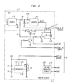
auxiliary board 3 and amonitor circuit 4 which communicate with each other through power andsignal conductors 10. Themonitor circuit 4 is connected to the UPS 5 through power andsignal conductors 9 and theauxiliary board 3 communicates with thecomputer 1 throughsignal conductors 11. In one embodiment, theauxiliary board 3 is a printed circuit board that is configured to plug into an open card slot in thecomputer 1 which might be a member of the PC-family of computers manufactured by the International Business Machines Corporation or those made by the Digital Equipment Corporation. Themonitor circuit 4 and UPS 5 may also be mounted in a common housing to enhance the utility and esthetic appeal of the system. - Figure 2 shows more details of the UPS 5 and the
monitor circuit 4 and their interconnection through power andsignal conductors 9. The UPS 5 is of a type known in the prior art, comprising generally abattery charger 25 which receives AC power from the main supply throughpower conductors 6, ablocking device 26 such as a diode, ameans 27 of supplying power when the main AC supply is interrupted or absent such as a storage battery, and aninverter 28. Thecharger 25 rectifies the input AC voltage to a DC voltage appropriate to the supply means 27; in one embodiment the supply means is a 12-volt battery therefore the output voltage of thecharger 25 is appropriate to maintain the battery fully charged. The DC output of thecharger 25 and supply means 27 is inverted back to AC by theinverter 28 and output to thecomputer 1 and other I/O devices 2. - When the main AC power supply is interrupted, the output of the
charger 25 drops to zero or near zero but the supply means 27 continues to supply power at substantially the same voltage to theinverter 28 and through it to the rest of the system as before. In this way the system is thus unaffected by the loss of the main power supply. A blocking device such as adiode 26 is usually inserted between the power supply means 27 and thecharger 25. Thediode 26 allows power to flow in only one direction and is oriented to prevent the flow of power from the supply means back through the charger into the failed main power supply. - Also shown in Figure 2 are details of the
monitor circuit 4 which may be located in the same housing as the UPS 5. The output of thecharger 25 is connected throughconductor 9 to atransistor 30 and throughconductor 10 to theauxiliary board 3. It will be appreciated that the function performed bytransistor 30 can also be implemented by a Darlington-connected set of transistors. When the main AC power supply is present, the output of thecharger 25 is a voltage substantially more positive than ground, e.g., 12 volts and thustransistor 30 is switched ON, thereby providing a ground path for relay coil 29ʹ which is being supplied a voltage from power supply means 27. The energization of the relay coil 29ʹ causes the normally-open relay contacts 29 to close. One of the contacts conducts AC power from theinverter 28 to thecomputer 1 and other I/O devices 2 through thepower conductor 7. The other relay contact provides another ground path for relay coil 29ʹ through another relay's normally closedcontact 31. - The other relay's coil 31ʹ is also supplied a voltage from the power supply means 27 and is similarly provided a ground return path through another
transistor 32 which is normally OFF. During normal operation, therefore, relay coil 29ʹ is energized while relay coil 31ʹ is not. When the main power supply is interrupted, the output voltage of thecharger 25 falls andtransistor 30 switches OFF, however, relay coil 29ʹ remains energized (andcontacts 29 remain closed) because its ground return path is still provided through the other relay'scontact 31. - As will be described in more detail below, the operation of the other relay is controlled by the
auxiliary board 3 through a signal sent via one ofconductors 10 to theother transistor 32. When that signal is present, while main power is interrupted,transistor 32 switches ON, thereby energizing relay coil 31ʹ and openingrelay contact 31. The ground return path for relay coil 29ʹ is thereby broken, de-energizing that coil and openingrelay contacts 29. As a result, AC power is no longer provided to thecomputer 1 or the other I/O devices 2, thereby conserving the energy remaining in the power supply means 27. - Also included in the
monitor circuit 4 is a circuit for generating a signal when the output voltage of the power supply means 27 drops below a predetermined value. It will be appreciated that there are many equivalent circuits which can perform this function. - In one embodiment, a
voltage comparator 33 has, as one input, a reference voltage provided by azener diode 34. The reference voltage remains constant as the output voltage of the power supply means 27 decreases due to power continuing to be supplied to thecomputer 1 and other I/O devices 2 when the main power supply is interrupted. Aresistor 35 limits the amount of current flowing through thezener diode 34. The other input of thecomparator 33 is a voltage proportional to the output voltage of the power supply means 27 which can be provided by means such as theresistive divider network 36. The division factor of thenetwork 36 is selected so that when the power supply means 27 is fully charged, the output ofcomparator 33 is a first voltage value and when the output voltage of the power supply means 27 drops to a predetermined level the output ofcomparator 33 switches to a second voltage value. The output of thecomparator 33 is connected to theauxiliary board 3 by one of theconductors 10. - Besides the simplicity of its circuitry, the above arrangement avoids the inflexibility and other drawbacks associated with the use of timers, particularly for embodiments in which the power supply means 27 are storage batteries. It is well known that the output voltage as a function of time of a battery varies with age, temperature and other factors. In embodiments of the present invention which include non-volatile memory devices requiring a continuous power supply independent of the main AC supply, it is important that enough stored energy remains in the power supply means 27 to continue to supply those memory devices. This can be assured despite changes in system power requirements resulting from changes in the number or electrical requirements of devices connected to
power conductor 7 by employing a device that directly monitors the condition of the power supply means 27, as shown in Figure 2. It will be appreciated that any suitable means for storing and recovering electrical energy may be used as supply means 27. - There is also included in the monitor circuit 4 a
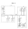
voltage regulator circuit 37 which provides a regulated output DC voltage of, for example, 5 volts for use by components on theauxiliary board 3 that are to be independent of the main power supply. Theregulator 37 is of a type known in the art and may, in an alternate embodiment, be located on theauxiliary board 3 rather than in themonitor circuit 4. In this alternate embodiment, the output voltage from the supply means 27 is connected throughconductor 10 to theauxiliary board 3. - Figure 3 shows part of the interconnections between the
computer 1 andauxiliary board 3. Thecomputer 1 includes a central processing unit (CPU) 13 for performing calculations and executing program instructions provided by read-only memory (ROM) 15 and random-access memory (RAM) 14. These devices are linked by a data- and address-bus 21 and their operation is synchronized by amaster system clock 12. In accordance with one embodiment of the present invention, theauxiliary board 3 includes anauxiliary ROM 19, anauxiliary RAM 20 and a largeauxiliary FIFO RAM 16 which are also connected to the data- and address-bus 21. Program instructions stored in theauxiliary ROM 19 are executed by theCPU 13. The operation of thelarge FIFO RAM 16 is controlled by acontrol circuit 17 andauxiliary clock 18. - In a higher capability computer, the CPU is driven by an operating system environment that is external to the CPU, and that system is usually stored in both nonvolatile ROM and volatile RAM. The operating system is specifically designed to operate with a given type of CPU; among the popular types currently available are the 8088, 8086, 80286 and 80386 made by Intel Corp., the V20, V30 and V40 made by Nippon Electric Company, and the 68000-series made by the Motorola Corp. IBM uses the Intel family of CPUs and provides a basic input/output system (BIOS) as part of its computers' ROM. In addition, a further portion of the operating system is usually provided to allow for CPU input/output and read/write operations involving disk drive-based storage media. The MicroSoft Corp. has developed several of these programs for various computer makers and currently provides PC-DOS, versions 3.1 and 3.2 among others, for use with IBM computers. Other operating systems such as UNIX, ZENIX and VMS are also available. Because access time to internal circuit-based RAM is less than to disk-drive based RAM, moder computers typically rely heavily on internal RAM for storage of the operating system, application programs, and other data. However, the computer's
internal RAM 14 is normally of the volatile type and so any contents it may have are lost when either the computer is intentionally powered down or the main power supply in interrupted. In accordance with one embodiment of the present invention, theauxiliary board 3 provides a largenonvolatile FIFO RAM 16 for storage of the contents ofRAM 14 and the CPU state. When the main power supply is interrupted, the normal operation of theCPU 13 is interrupted and a program stored in anauxiliary ROM 19 is executed by the CPU. - Although the embodiment depicted in the accompanying figures uses an auxiliary circuit board that is inserted into the computer, it is within the scope of the present invention to include components necessary to accomplish the function of the auxiliary board within the main computer circuit board or "mother board" itself. It will be appreicated by one of ordinary skill in the art that the present invention can be used with any of the various types of CPU or their successors which are driven by any type of external operating system. This would include the CPUs and operating system which are employed to control automated assembly lines such as those for automobiles. Furthermore, the present invention can save the contents of other auxiliary boards such as video cards and extended graphics adaptor boards which are used with the CPU.
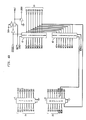
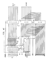
- Referring to Figures 4a-4e, there are shown details of the components of the
auxiliary board 3.Buffers 41 have their inputs connected to the address lines of the computer's data- and address-bus 21 and to the computer's control signals; their outputs are connected to other components on theauxiliary board 3. The buffers serve to isolate electrically the auxiliary board from the computer, thus avoiding possible undesirable interactions, while transmitting address information to the auxiliary board. Bus transceivers are connected to the data lines of the computer's data- and address-bus 21 and to other components on theauxiliary board 3. Information moves in both directions through thetransceivers 42 which still help to provide electrical isolation between theauxiliary board 3 and thecomputer 1. Other gates and signals are provided to control the operation of thetransceivers 42. One of the transceivers is used for the largeauxiliary FIFO memory 16 while the other transceiver is used for theauxiliary ROM 19 and theauxiliary RAM 20. - Figure 4b shows a
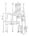
means 43 for setting the program address of theauxiliary board 3 and for determining when that address is received on certain of the address lines from the computer. The board address is set by selecting the ON/OFF position of a series of switches SW1. The voltage levels of the address lines are compared to the voltage levels determined by the switches; when the corresponding levels match, a decoder means 44 is enabled. The decoder means 44 then outputs one of several control signals to the other components of theauxiliary board 3 in accordance with the values of three of the address lines and the control signals IOR and IOW. - Figure 4c shows a
means 46 for setting the program address of theauxiliary ROM 19 andauxiliary RAM 20 and for determining when that address is received on certain of the address lines from the computer. The address is set by selecting the ON/OFF position of another series of switches SW2. The voltage levels of the address lines are compared to the voltage levels determined by the switches; when the corresponding levels match, thememories means 47. At the same time, the address set by the series of switches is output to the computer through a buffer. In this way, the computer is continually informed of the address of thememories ROM 19 contains substantially all of the program code used by the present invention. The instructions stored in theROM 19 are executed by theCPU 13.RAM 20 is used to store the configuration of the computer system and the state of theCPU 13, and is a substantially smaller amount of memory than theauxiliary FIFO memory 16. The address of a particular cell in thememories buffers 41 from the computer's data- and address-bus 21. Information at that cell location is then read, in the case of bothmemories RAM 20, through one of thetransceivers 42 from or to thebus 21. - Figure 4d shows the large
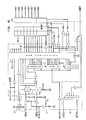
auxiliary memory 16 and itscontrol circuits 17 andclock 18. In one embodiment, thelarge memory 16 is an array of dynamic random access memory circuit that thus depend on a continuous supply of power to maintain their contents. In this embodiment the continuous supply of power is provided by thevoltage regulator circuit 37 inmonitor circuit 4. The capacity of thememory 16 need only be large enough to store the entire contents of the computer'svolatile RAM 14 and the CPU state, together with the contents of any other boards the loss of which it is desired to have prevented. It will therefore be appreciated that the function ofmemory 16 can be performed by any suitable non-volatile random access memory including magnetic bubble or disk-drive types which do not require continuous power. The nature of thecontrol circuit 17 andclock 18 would likewise change accordingly. - The
control circuit 17 includes several gates which enable reading and writing to thememory 16 according to the condition of several control signals. In one embodiment, addresses for the cells in thememory 16 are generated sequentially by a set of counters, thus thelarge memory 16 operates as a first-in-first-out (FIFO) device. It will be appreciated that the addresses for thememory 16 can be provided by other forms of circuitry that would provide random access to the memory cells. Also included incontrol circuit 17 is an integrated circuit dynamic RAM controller which helps to control the operation of thememory 16. Finally, because of the nature of dynamic random access memory circuits, a group of OR gates provides alternating row and column address strobes for thememory 16. - The operation of the
memory 16 andcontrol circuit 17 is synchronized by theauxiliary clock circuit 18; these circuits are provided continuous power from the supply means 27 through theregulator 37 and thus continue to operate and maintain the contents of thememory 16 even when the main power supply is interrupted. The operation of the auxiliary board memory circuits is synchronized with the computer'smaster system clock 12 by thecircuitry 48 which also ensures that there are no latch-up problems experienced by the system when the auxiliary board is installed. - It will be appreciated that the large
auxiliary memory 16 may be made available to the computer operator for use during normal operation, i.e., when the main power supply is not interrupted. The memory can thus be employed in the manner of a VDisk which is a designation of the operating system PC-DOS, versions 3.1 and 3.2. The memory therefore appears to be an element of the actual hardware configuration of the computer and is treated as another peripheral device. Similarly, thelarge memory 16 can be made available as a RAMDisk, which is a designation of several independent software makers, or other equivalent. In embodiments of the present invention which use thelarge memory 16 as such a "virtual" disk drive, any contents that are stored in the memory must be removed and stored elsewhere before the memory is made available to compensate for a power failure. This can be provided by automatically evacuating the contents of thememory 16 to another non-volatile memory such as a hard disk drive peripheral before the contents of the computer'sother RAM 14 and CPU state are stored. - Figure 4e shows interface circuitry between the computer and the other components of the present invention which is used to inform the
CPU 13 of the status of the auxiliary board and the work-saving system. This information is transmitted through a buffer to the CPU along thebus 21 and includes status information from theUPS 5 and monitorcircuit 4. A circuit 50 is provided which generates an interrupt signal for the CPU according to the simultaneous occurrence of a low-voltage signal from thecomparator 33 and a signal that indicates the continuing connection of theinverter 28 toconductor 7. - The program instructions in accordance with the present invention which are executed by the
CPU 13 are provided from theauxiliary ROM 19 and from the computer'sRAM 14. The latter portion of the program instructions is interactive with the operating system in use with the computer. For example, in the PC-DOS environment, a small number of instructions is stored in an AUTOEXEC.BAT file which is automatically executed when the computer is powered up and the operating system "boots" up. As already noted, these instructions can be written to function with any operating system such as UNIX, ZENIX, VMS, etc. for execution by any of the various types of CPU which are driven by an operating system environment external to the CPU. In one embodiment, this RAM-resident, DOS-related program code requires 96 bytes of storage. - Figure 5a shows a flowchart of a system startup program module in accordance with the present invention. After a display announcing the presence of the work-saving system in sent to the system's output display, a program module called the Power Fail Interrupt Service Routine in loaded from the
auxiliary ROM 19 into theRAM 14 and installed under the control of the operating system. The circuitry of theauxiliary board 3 is then reset and prepared for a power interruption by initializing or setting up thelarge memory 16 and enabling the interrupt signals to the CPU. After these preparations are completed, program control returns for either continued execution of the AUTOEXEC.BAT file which is a file "non-resident" under DOS or to other programs "resident" under the operating system. - Also installed in the AUTOEXEC.BAT file is a program module for control of recovery of the computer system after a power interruption. A flowchart of this program is shown in Figure 5b. When the system "boots up," the
auxiliary board 3 is addressed and interrogated as to whether a system save in the event of a power failure has occurred. If a save has occurred, control of the CPU is transferred to firmware programs in theauxiliary ROM 19. If no save has been necessary, program control returns to the AUTOEXEC.BAT file or to the operating system for normal booting. It will be appreciated that the program can be designed to prevent a rebooting of the operation system to allow for stabilization of power conditions. Short power interrupts may require a time period to allow the computer's power supplies to drain properly before power should be reapplied. Also, means may be included to monitor the stability of the main power supply and prevent rebooting before a continuous period of stable main power has elapsed. - The bulk of the program code for controlling the work-saving system of the present invention is stored, in one embodiment, in the
auxiliary memory 19. A flowchart of the Power Fail Interrupt Service Routine so stored is shown in Figure 5c. When a power interruption is detected, the contents of the CPU registers are stored in theauxiliary RAM 20. The status of the interrupt signals are checked and the user is informed that the computer system is operating on backup power. At this point the operator can be given the option of overriding the continued execution of this program module. For computer systems such as assembly line controllers which do not have output CRT displays, a small device such as a liquid crystal display (LCD) may be provided with theUPS 5 and monitorcircuit 4. If the system is not yet to be saved, the interrupts are cleared, the values of the registers restored and CPU control is returned to its location at the start of module execution. If the system is to be saved, the CPU state consisting of stacks, vectors, pointers, etc. is saved in theauxiliary RAM 20. If thelarge memory 16 is being used as a RAM Disk, VDisk or equivalent, its contents are saved into a data file on a nonvolatile medium such as a hard disk. After this step or, if thelarge memory 16 is not being used, the contents of the computer'sRAM 19 is stored in thelarge memory 16. Theinverter 28 is then disconnected through the opening ofrelay contacts 29 to conserve the remaining energy stored in the supply means 27. - When the main power supply has been restored, another program module stored in
auxiliary ROM 19 directs the recovery of the system to its condition when it was shutdown. A flowchart of this program module is shown in Figure 5d. The contents of the computer'sRAM 14 are reloaded into that RAM from the largeauxiliary memory 16 and the state of the CPU is reset to its condition when it was shutdown. The CPU's interrupt stack is reset in the same way, as are the values of the CPU's registers. When these operations are complete, the computer system has been reset to exactly its condition when it was shutdown and the execution which was in progress when power was interrupted continues as if it had not been interrupted. - The preferred embodiments of the present invention can provide an inexpensive work-saving system for use with a higher capability computer to prevent unintentional loss of data.
- With the preferred embodiments of the present invention, the system can automatically provide for an orderly shutdown of the operation of the computer.
- In the preferred embodiments of the present invention, the system can restore the computer to its operating state when electric power is restored.
- The preferred embodiments of the present invention can provide that the work-saving system functions automatically but allows for its possible override by a human operator.
- The preferred embodiments of the present invention can provide a system wherein the additional memory provided with the work-saving system is available for use by the computer during its normal operation.
- With the preferred embodiments of the present invention, the work-saving system can also save the contents of auxiliary circuit boards such as extended graphics adaptor boards.
- In accordance with the preferred embodiments of the present invention, such a work-saving system can be incorporated onto the mother board of the computer which is to be protected.
- In the preferred embodiments of the present invention, the work-saving system can prevent the loss of data in any computer having a CPU which is driven by an operating system environment external to the CPU.
- It will be appreciated by those of ordinary skill in the art that the present invention can be embodied in other specific forms without departing from the spirit or the essential characteristic thereof.
- For example, although specifically disclosed with regard to its use with personal computers the invention also has applicability to other CPU-based systems. One such system might be a PAXB telephone exchange, where the invention operates to save the status of existing line connections so that ongoing conversations can be maintained even when the control CPU is shut down for the duration of the power failure. The presently disclosed embodiments are therefore considered in all respects to be illustrative and not restrictive. The scope of the invention is illustrated by the appended claims rather than the foregoing description and all changes that come within the meaning and range of equivalents thereof are intended to be embraced therein.
Claims (10)
means for supplying electric power to the computer after a main power interruption;
means for monitoring the main electric power supply and for generating a signal indicative of an interruption thereof;
means for directing an operation of the computer and for conserving power to be supplied by the power supply means, the directing means being responsive to the interruption signal and including an interrupt program stored in a non-volatile memory; and
means for storing the application program and operating system stored in the RAM and the CPU's state, the storing means being responsive to the directing means.
means for supplying electric power to the computer after a main power interruption;
means for monitoring the main electric power supply and for generating a signal indicative of an interruption thereof and a signal indicative of a restoration thereof;
means for directing an orderly shutdown operation of the computer when the main power supply is interrupted and for restarting the computer when main power is restored, the directing means being responsive to the signals of the monitoring means and including an interrupt program in a non-volatile memory; and
means for storing the application program and operating system stored in the RAM and the CPU's state, the storing means being responsive to the directing means.
Applications Claiming Priority (2)
| Application Number | Priority Date | Filing Date | Title |
|---|---|---|---|
| US894570 | 1986-08-08 | ||
| US06/894,570 US4763333A (en) | 1986-08-08 | 1986-08-08 | Work-saving system for preventing loss in a computer due to power interruption |
Publications (2)
| Publication Number | Publication Date |
|---|---|
| EP0256815A2 true EP0256815A2 (en) | 1988-02-24 |
| EP0256815A3 EP0256815A3 (en) | 1989-10-11 |
Family
ID=25403259
Family Applications (1)
| Application Number | Title | Priority Date | Filing Date |
|---|---|---|---|
| EP87307030A Withdrawn EP0256815A3 (en) | 1986-08-08 | 1987-08-07 | Preventing data loss in computers |
Country Status (7)
| Country | Link |
|---|---|
| US (1) | US4763333A (en) |
| EP (1) | EP0256815A3 (en) |
| JP (1) | JPS63184124A (en) |
| KR (1) | KR880003251A (en) |
| BR (1) | BR8704061A (en) |
| CA (1) | CA1282177C (en) |
| IN (1) | IN171015B (en) |
Cited By (18)
| Publication number | Priority date | Publication date | Assignee | Title |
|---|---|---|---|---|
| EP0376488A2 (en) * | 1988-12-30 | 1990-07-04 | Pitney Bowes, Inc. | EPM having an improvement in accounting update security |
| EP0393631A2 (en) * | 1989-04-20 | 1990-10-24 | Sanyo Electric Co., Ltd | Initial process system after cutoff of power source and corresponding process system |
| EP0404061A2 (en) * | 1989-06-23 | 1990-12-27 | Kabushiki Kaisha Toshiba | Computer having a resume function and operable on an internal power source |
| EP0429781A2 (en) * | 1989-11-30 | 1991-06-05 | Kabushiki Kaisha Toshiba | Resume control system and method for executing resume processing while checking operation mode of CPU |
| DE4009523A1 (en) * | 1990-03-24 | 1991-09-26 | Autonom Computer Vertrieb Gmbh | COMPUTER CONTROL SYSTEM |
| FR2685794A1 (en) * | 1991-12-31 | 1993-07-02 | Gutierrez Lopez Jose | SECURITY DEVICE FOR COMPUTERS WITH UNINTERRUPTED POWER. |
| US5276890A (en) * | 1989-11-30 | 1994-01-04 | Kabushiki Kaisha Toshiba | Resume control system and method for executing resume processing while checking operation mode of CPU |
| FR2701131A1 (en) * | 1993-02-03 | 1994-08-05 | G2Pb | Inverter device, especially for micro- or mini-computing. |
| EP0683456A1 (en) * | 1989-12-22 | 1995-11-22 | Tandem Computers Incorporated | Fault-tolerant computer system with online reintegration and shutdown/restart |
| EP0805386A1 (en) * | 1996-04-29 | 1997-11-05 | International Business Machines Corporation | Suspend induced by AC power disturbance |
| US6229450B1 (en) | 1999-03-15 | 2001-05-08 | The Detroit Edison Company | Power interruption monitoring apparatus |
| GB2418502A (en) * | 2004-09-27 | 2006-03-29 | Hewlett Packard Development Co | Responding to dc power degradation |
| WO2007071590A1 (en) * | 2005-12-20 | 2007-06-28 | Robert Bosch Gmbh | Method for recognizing a power outage in a data memory and recovering the data memory |
| CN100380268C (en) * | 1999-09-16 | 2008-04-09 | 国际商业机器公司 | Computer and power source control method thereof |
| EP1953619A1 (en) * | 2007-02-01 | 2008-08-06 | Siemens Aktiengesellschaft | Method for saving data in a data processing system and data processing system |
| EP2212794A1 (en) * | 2007-10-05 | 2010-08-04 | Joseph A. Ashwood | Scalable mass data storage device |
| US9367400B2 (en) | 2010-12-14 | 2016-06-14 | Microsoft Technology Licensing, Llc | System reset |
| CN110023911A (en) * | 2016-10-31 | 2019-07-16 | 日立汽车系统株式会社 | Electronic control unit and its data guard method |
Families Citing this family (88)
| Publication number | Priority date | Publication date | Assignee | Title |
|---|---|---|---|---|
| DE3828858A1 (en) * | 1987-09-29 | 1989-04-06 | Pioneer Electronic Corp | NAVIGATION DEVICE FOR A MOTOR VEHICLE |
| AU616213B2 (en) * | 1987-11-09 | 1991-10-24 | Tandem Computers Incorporated | Method and apparatus for synchronizing a plurality of processors |
| CA2003338A1 (en) * | 1987-11-09 | 1990-06-09 | Richard W. Cutts, Jr. | Synchronization of fault-tolerant computer system having multiple processors |
| DE3744200A1 (en) * | 1987-12-24 | 1989-07-13 | Heidelberger Druckmasch Ag | DEVICE, METHOD FOR BACKING UP DATA |
| US5012406A (en) * | 1988-04-19 | 1991-04-30 | Power Card Supply | Line of power interruption in predetermined area of internal permanent memory |
| JPH01279312A (en) * | 1988-04-30 | 1989-11-09 | Toshiba Corp | Computer system |
| US5218691A (en) * | 1988-07-26 | 1993-06-08 | Disk Emulation Systems, Inc. | Disk emulation system |
| US5218707A (en) * | 1988-10-28 | 1993-06-08 | Dallas Semiconductor Corp. | Integrated circuit with remappable interrupt pins |
| US4965717A (en) * | 1988-12-09 | 1990-10-23 | Tandem Computers Incorporated | Multiple processor system having shared memory with private-write capability |
| AU625293B2 (en) * | 1988-12-09 | 1992-07-09 | Tandem Computers Incorporated | Synchronization of fault-tolerant computer system having multiple processors |
| US5253360A (en) * | 1988-12-16 | 1993-10-12 | Kabushiki Kaisha Toshiba | Facsimile device having continuous operating capabilities immediately after recovery from trouble and related method |
| US5247164A (en) * | 1989-01-26 | 1993-09-21 | Hitachi Maxell, Ltd. | IC card and portable terminal |
| JP2940676B2 (en) * | 1989-06-16 | 1999-08-25 | 株式会社リコー | Facsimile machine |
| US5218607A (en) * | 1989-06-23 | 1993-06-08 | Kabushiki Kaisha Toshiba | Computer having a resume function and operable on an internal power source |
| EP0415376A3 (en) * | 1989-08-28 | 1992-04-08 | Kabushiki Kaisha Toshiba | Computer unit with a resume function |
| EP0418448A1 (en) * | 1989-09-22 | 1991-03-27 | Computers Iberica S.A. | A system for the protection against mains supply failure for computers by storing the processed information held in the volatile memory |
| US5182769A (en) * | 1989-10-19 | 1993-01-26 | Kabushiki Kaisha Toshiba | Telephone set having a volatile memory |
| US5151855A (en) * | 1989-10-19 | 1992-09-29 | Saturn Corporation | Multiple microprocessor single power supply system shutdown |
| US5247655A (en) * | 1989-11-07 | 1993-09-21 | Chips And Technologies, Inc. | Sleep mode refresh apparatus |
| US5021983B1 (en) * | 1989-11-13 | 1996-05-28 | Chips & Technologies Inc | Suspend/resume apparatus and method for reducing power consumption in battery powered computers |
| US5327553A (en) * | 1989-12-22 | 1994-07-05 | Tandem Computers Incorporated | Fault-tolerant computer system with /CONFIG filesystem |
| US5317752A (en) * | 1989-12-22 | 1994-05-31 | Tandem Computers Incorporated | Fault-tolerant computer system with auto-restart after power-fall |
| US5295258A (en) * | 1989-12-22 | 1994-03-15 | Tandem Computers Incorporated | Fault-tolerant computer system with online recovery and reintegration of redundant components |
| JPH03226813A (en) * | 1990-01-31 | 1991-10-07 | Toshiba Corp | Portable electronic equipment |
| US5151907A (en) * | 1990-02-20 | 1992-09-29 | Robbins Walter A | Auxiliary power supply for continuation of computer system operation during commercial AC power failure |
| JPH0479098A (en) * | 1990-07-20 | 1992-03-12 | Fujitsu Ltd | Semiconductor storage device |
| US5390322A (en) * | 1991-02-01 | 1995-02-14 | O'brien; Michael J. | Apparatus and method for retaining cycle memory in electronic sterilizer controls |
| US5241508A (en) * | 1991-04-03 | 1993-08-31 | Peripheral Land, Inc. | Nonvolatile ramdisk memory |
| IT1254937B (en) * | 1991-05-06 | 1995-10-11 | DYNAMIC UPDATE OF NON-VOLATILE MEMORY IN A COMPUTER SYSTEM | |
| DE4215063C2 (en) * | 1991-05-10 | 1999-11-25 | Intel Corp | Device and method for changing pages in a non-volatile memory |
| US5303171A (en) * | 1992-04-03 | 1994-04-12 | Zenith Data Systems Corporation | System suspend on lid close and system resume on lid open |
| US5652890A (en) * | 1991-05-17 | 1997-07-29 | Vantus Technologies, Inc. | Interrupt for a protected mode microprocessor which facilitates transparent entry to and exit from suspend mode |
| US5551033A (en) | 1991-05-17 | 1996-08-27 | Zenith Data Systems Corporation | Apparatus for maintaining one interrupt mask register in conformity with another in a manner invisible to an executing program |
| US5394527A (en) * | 1991-05-17 | 1995-02-28 | Zenith Data Systems Corporation | Method and apparatus facilitating use of a hard disk drive in a computer system having suspend/resume capability |
| EP0584257B1 (en) * | 1991-05-17 | 2004-08-04 | Packard Bell NEC, Inc. | Power management capability for a microprocessor having backward compatibility |
| JPH077317B2 (en) * | 1991-06-10 | 1995-01-30 | 松下電器産業株式会社 | System restart device |
| JPH077316B2 (en) * | 1991-06-10 | 1995-01-30 | 松下電器産業株式会社 | System restart device |
| US5680570A (en) * | 1991-06-12 | 1997-10-21 | Quantum Corporation | Memory system with dynamically allocatable non-volatile storage capability |
| EP0523652B1 (en) * | 1991-07-16 | 1999-02-03 | Canon Kabushiki Kaisha | Electronic apparatus with resume function |
| US5414861A (en) * | 1991-09-11 | 1995-05-09 | Fujitsu Limited | Data protection system using different levels of reserve power to maintain data in volatile memories for any period of time |
| JPH06236284A (en) * | 1991-10-21 | 1994-08-23 | Intel Corp | Method for preservation and restoration of computer-system processing state and computer system |
| JPH05324139A (en) * | 1992-01-16 | 1993-12-07 | Intel Corp | Power down controlling system of mcu |
| US6193422B1 (en) | 1992-04-03 | 2001-02-27 | Nec Corporation | Implementation of idle mode in a suspend/resume microprocessor system |
| US5353248A (en) * | 1992-04-14 | 1994-10-04 | Altera Corporation | EEPROM-backed FIFO memory |
| EP1262863B1 (en) * | 1992-09-17 | 2006-11-22 | Kabushiki Kaisha Toshiba | Portable computer having dedicated register group and peripheral controller bus between system bus and peripheral controller |
| JPH06119510A (en) * | 1992-10-07 | 1994-04-28 | Mitsubishi Electric Corp | Memory card |
| JP2880863B2 (en) * | 1992-10-29 | 1999-04-12 | 株式会社東芝 | Suspend control method and system |
| KR950013305B1 (en) * | 1992-11-10 | 1995-11-02 | 삼성전자주식회사 | The paging receiver |
| US5606681A (en) * | 1994-03-02 | 1997-02-25 | Eec Systems, Inc. | Method and device implementing software virtual disk in computer RAM that uses a cache of IRPs to increase system performance |
| US5555510A (en) * | 1994-08-02 | 1996-09-10 | Intel Corporation | Automatic computer card insertion and removal algorithm |
| KR970010634B1 (en) * | 1994-10-25 | 1997-06-28 | 삼성전자 주식회사 | Metwork hibernation system |
| JP3292864B2 (en) * | 1995-02-07 | 2002-06-17 | 株式会社日立製作所 | Data processing device |
| US5822581A (en) * | 1995-09-29 | 1998-10-13 | Intel Corporation | Method for CMOS configuration information storage and retrieval in flash |
| KR0156802B1 (en) * | 1995-11-07 | 1998-11-16 | 김광호 | Network hybernation system |
| US5974552A (en) * | 1995-12-29 | 1999-10-26 | Samsung Electronics Co., Ltd. | Method and apparatus for executing a scheduled operation after wake up from power off state |
| US5708589A (en) * | 1996-04-08 | 1998-01-13 | Vaughn Manufacturing Corporation | Error recovery system for an energy controller for an electric water heater |
| US5661677A (en) | 1996-05-15 | 1997-08-26 | Micron Electronics, Inc. | Circuit and method for on-board programming of PRD Serial EEPROMS |
| US5930504A (en) * | 1996-07-22 | 1999-07-27 | Intel Corporation | Dynamic nonvolatile memory update in a computer system |
| US5935259A (en) | 1996-09-24 | 1999-08-10 | Apple Computer, Inc. | System and method for preventing damage to media files within a digital camera device |
| US5831347A (en) * | 1996-10-09 | 1998-11-03 | Thomson Consumer Electronics, Inc. | Apparatus for determining if the duration of a power failure exceeded predetermined limits |
| US5889933A (en) * | 1997-01-30 | 1999-03-30 | Aiwa Co., Ltd. | Adaptive power failure recovery |
| KR100281535B1 (en) * | 1997-02-12 | 2001-02-15 | 윤종용 | Computer system and its control method |
| US6178523B1 (en) * | 1998-06-12 | 2001-01-23 | Philips Consumer Communications Lp | Battery-operated device with power failure recovery |
| US6408397B1 (en) | 1999-05-24 | 2002-06-18 | Dell Usa, L.P. | Using RTC wake-up to enable recovery from power failures |
| US6601181B1 (en) | 1999-12-14 | 2003-07-29 | Gateway, Inc. | Uninterruptible power supply apparatus and method |
| US6968469B1 (en) | 2000-06-16 | 2005-11-22 | Transmeta Corporation | System and method for preserving internal processor context when the processor is powered down and restoring the internal processor context when processor is restored |
| JP2002062956A (en) * | 2000-08-21 | 2002-02-28 | Sankyo Seiki Mfg Co Ltd | Service interruption processing method and service interruption processing device |
| JP2003016400A (en) * | 2001-06-28 | 2003-01-17 | Sankyo Seiki Mfg Co Ltd | Power failure detecting device and card reader equipped with the same power failure detecting device |
| US6965989B1 (en) * | 2001-08-14 | 2005-11-15 | Network Appliance, Inc. | System and method for fast reboot of a file server |
| TW546586B (en) * | 2001-11-14 | 2003-08-11 | Via Tech Inc | Personal computer peripheral device and initialization method thereof |
| US6990603B2 (en) * | 2002-01-02 | 2006-01-24 | Exanet Inc. | Method and apparatus for securing volatile data in power failure in systems having redundancy |
| US20040148547A1 (en) * | 2003-01-28 | 2004-07-29 | Jim Thompson | UPS-based file data storage apparatus and computer program products |
| US7836339B2 (en) * | 2003-03-31 | 2010-11-16 | Intel Corporation | Computer memory power backup |
| TWI226541B (en) * | 2003-04-09 | 2005-01-11 | Asustek Comp Inc | Method preventing user's data stored in PDA from losing and device thereof |
| US8250406B2 (en) * | 2003-08-19 | 2012-08-21 | Intel Corporation | Operational state preservation in the absence of AC power |
| CN1327344C (en) * | 2003-08-19 | 2007-07-18 | 英特尔公司 | Bios for saving and restoring operational state in the absence of AC power |
| US7315951B2 (en) * | 2003-10-27 | 2008-01-01 | Nortel Networks Corporation | High speed non-volatile electronic memory configuration |
| KR100524474B1 (en) * | 2003-11-10 | 2005-10-31 | 삼성전자주식회사 | Computer sysytem and control method thereof |
| US7318170B2 (en) * | 2004-07-09 | 2008-01-08 | Spyder Navigations, Llc | Protection of non-volatile memory component against data corruption due to physical shock |
| US20060227605A1 (en) * | 2005-01-05 | 2006-10-12 | Choi David S | Memory architectures including non-volatile memory devices |
| JP4926577B2 (en) * | 2006-07-07 | 2012-05-09 | 富士重工業株式会社 | Vehicle fuel cooling system |
| TW200837548A (en) * | 2007-03-09 | 2008-09-16 | Acer Inc | Method for reducing NB battery change operation time and the battery detector thereof |
| US20090040842A1 (en) * | 2007-08-06 | 2009-02-12 | Sandisk Corporation, A Delaware Corporation | Enhanced write abort mechanism for non-volatile memory |
| US7599241B2 (en) * | 2007-08-06 | 2009-10-06 | Sandisk Corporation | Enhanced write abort mechanism for non-volatile memory |
| US9389665B1 (en) * | 2015-06-19 | 2016-07-12 | Rockwell Collins, Inc. | Power warning monitor system and method |
| CN104991629B (en) * | 2015-07-10 | 2017-11-24 | 英业达科技有限公司 | Power-fail detecting system and its method |
| US10423783B2 (en) * | 2016-12-19 | 2019-09-24 | Intel Corporation | Methods and apparatus to recover a processor state during a system failure or security event |
| CN112084085B (en) * | 2019-06-14 | 2023-05-09 | 佛山市顺德区顺达电脑厂有限公司 | System outage recording method |
Citations (2)
| Publication number | Priority date | Publication date | Assignee | Title |
|---|---|---|---|---|
| US4307455A (en) * | 1978-02-27 | 1981-12-22 | Rockwell International Corporation | Power supply for computing means with data protected shut-down |
| JPS5990295A (en) * | 1982-11-12 | 1984-05-24 | Nec Corp | Backup system of main storage device |
Family Cites Families (11)
| Publication number | Priority date | Publication date | Assignee | Title |
|---|---|---|---|---|
| JPS5252525A (en) * | 1975-10-27 | 1977-04-27 | Mitsubishi Electric Corp | Service interruption protection system or infrmation processing system |
| GB1545169A (en) * | 1977-09-22 | 1979-05-02 | Burroughs Corp | Data processor system including data-save controller for protection against loss of volatile memory information during power failure |
| JPS5494850A (en) * | 1978-01-11 | 1979-07-26 | Nissan Motor | Arithmetic processor |
| IT1136829B (en) * | 1980-03-21 | 1986-09-03 | Philips Nv | METHOD FOR CONTROLLING A APPLIANCE, WHICH IS OPERATED BY A SOLID STATE PROCESSOR AND ENHANCED BY A POWER SUPPLY, IN THE EVENT OF A MOTOR POWER FAILURE, AND APPARATUS USING THE METHOD |
| US4327410A (en) * | 1980-03-26 | 1982-04-27 | Ncr Corporation | Processor auto-recovery system |
| US4323987A (en) * | 1980-03-28 | 1982-04-06 | Pitney Bowes Inc. | Power failure memory support system |
| US4447887A (en) * | 1980-09-02 | 1984-05-08 | Fujitsu Fanuc Limited | Method of rewriting data in non-volatile memory, and system therefor |
| JPS5755458A (en) * | 1980-09-19 | 1982-04-02 | Fujitsu Ltd | Initial diagnostic system at power restoration |
| JPS59192740U (en) * | 1983-06-02 | 1984-12-21 | パイオニア株式会社 | computer equipment |
| GB2145253A (en) * | 1983-08-17 | 1985-03-20 | Philips Electronic Associated | Method of controlling a domestic appliance |
| JPS6197730A (en) * | 1984-10-17 | 1986-05-16 | Fujitsu Ltd | Power failure processing system for computer system |
-
1986
- 1986-08-08 US US06/894,570 patent/US4763333A/en not_active Expired - Fee Related
-
1987
- 1987-07-29 IN IN657/DEL/87A patent/IN171015B/en unknown
- 1987-08-06 KR KR1019870008633A patent/KR880003251A/en not_active Application Discontinuation
- 1987-08-07 EP EP87307030A patent/EP0256815A3/en not_active Withdrawn
- 1987-08-07 BR BR8704061A patent/BR8704061A/en unknown
- 1987-08-07 CA CA000543976A patent/CA1282177C/en not_active Expired - Lifetime
- 1987-08-07 JP JP62196504A patent/JPS63184124A/en active Pending
Patent Citations (2)
| Publication number | Priority date | Publication date | Assignee | Title |
|---|---|---|---|---|
| US4307455A (en) * | 1978-02-27 | 1981-12-22 | Rockwell International Corporation | Power supply for computing means with data protected shut-down |
| JPS5990295A (en) * | 1982-11-12 | 1984-05-24 | Nec Corp | Backup system of main storage device |
Non-Patent Citations (4)
| Title |
|---|
| ELECTRICAL DESIGN NEWS, vol. 28, no. 8, April 1983, pages 123-131, Boston, Massachusetts, US; R.H. CUSHMAN: "Hands-on investigations help exploit CMOS designs" * |
| IBM TECHNICAL DISCLOSURE BULLETIN, vol. 17, no 12, May 1975, pages 3660-3661, New York, US; R.S. CAPOWSKI et al.: "Data retention system" * |
| IBM TECHNICAL DISCLOSURE BULLETIN, vol. 17, no. 5, October 1974, pages 1449-1450, New York, US; R.O. HIPPERT et al.: "Saving random-access memory in the event of a power failure" * |
| PATENT ABSTRACTS OF JAPAN, vol. 8, no. 208 (P-302)[1645], 21st September 1984; & JP-A-59 090 295 (NIPPON DENKI K.K.) 24-05-1984 * |
Cited By (34)
| Publication number | Priority date | Publication date | Assignee | Title |
|---|---|---|---|---|
| EP0376488A2 (en) * | 1988-12-30 | 1990-07-04 | Pitney Bowes, Inc. | EPM having an improvement in accounting update security |
| EP0376488A3 (en) * | 1988-12-30 | 1991-11-06 | Pitney Bowes, Inc. | Epm having an improvement in accounting update security |
| EP0393631A2 (en) * | 1989-04-20 | 1990-10-24 | Sanyo Electric Co., Ltd | Initial process system after cutoff of power source and corresponding process system |
| EP0393631A3 (en) * | 1989-04-20 | 1992-02-26 | Sanyo Electric Co., Ltd | Initial process system after cutoff of power source and corresponding process system |
| EP0404061A2 (en) * | 1989-06-23 | 1990-12-27 | Kabushiki Kaisha Toshiba | Computer having a resume function and operable on an internal power source |
| EP0404061A3 (en) * | 1989-06-23 | 1992-04-15 | Kabushiki Kaisha Toshiba | Computer having a resume function and operable on an internal power source |
| US5276890A (en) * | 1989-11-30 | 1994-01-04 | Kabushiki Kaisha Toshiba | Resume control system and method for executing resume processing while checking operation mode of CPU |
| EP0429781A2 (en) * | 1989-11-30 | 1991-06-05 | Kabushiki Kaisha Toshiba | Resume control system and method for executing resume processing while checking operation mode of CPU |
| EP0429781A3 (en) * | 1989-11-30 | 1992-05-20 | Kabushiki Kaisha Toshiba | Resume control system and method for executing resume processing while checking operation mode of cpu |
| EP0683456A1 (en) * | 1989-12-22 | 1995-11-22 | Tandem Computers Incorporated | Fault-tolerant computer system with online reintegration and shutdown/restart |
| DE4009523A1 (en) * | 1990-03-24 | 1991-09-26 | Autonom Computer Vertrieb Gmbh | COMPUTER CONTROL SYSTEM |
| ES2040631A2 (en) * | 1991-12-31 | 1993-10-16 | Gutierrez Lopez Jose Antonio | Safety device for computers with uninterrupted power feed |
| BE1006142A3 (en) * | 1991-12-31 | 1994-05-24 | Lopez Jose Antonio Gutierrez | Safety device for a permanent power computers. |
| FR2685794A1 (en) * | 1991-12-31 | 1993-07-02 | Gutierrez Lopez Jose | SECURITY DEVICE FOR COMPUTERS WITH UNINTERRUPTED POWER. |
| FR2701131A1 (en) * | 1993-02-03 | 1994-08-05 | G2Pb | Inverter device, especially for micro- or mini-computing. |
| EP0610133A1 (en) * | 1993-02-03 | 1994-08-10 | Investrade | Apparatus incorporating an inverter, in particular for mini- or micro-computing |
| EP0805386A1 (en) * | 1996-04-29 | 1997-11-05 | International Business Machines Corporation | Suspend induced by AC power disturbance |
| US5765001A (en) * | 1996-04-29 | 1998-06-09 | International Business Machines Corporation | Computer system which is operative to change from a normal operating state to a suspend state when a power supply thereof detects that an external source is no longer providing power to said power supply at a predetermined level |
| EP1988443A3 (en) * | 1996-04-29 | 2012-01-04 | Lenovo (Singapore) Pte. Ltd. | Suspend induced by AC power disturbance |
| US6229450B1 (en) | 1999-03-15 | 2001-05-08 | The Detroit Edison Company | Power interruption monitoring apparatus |
| CN100380268C (en) * | 1999-09-16 | 2008-04-09 | 国际商业机器公司 | Computer and power source control method thereof |
| GB2418502A (en) * | 2004-09-27 | 2006-03-29 | Hewlett Packard Development Co | Responding to dc power degradation |
| GB2418502B (en) * | 2004-09-27 | 2008-08-20 | Hewlett Packard Development Co | Responding to DC power degradation |
| US7512825B2 (en) | 2004-09-27 | 2009-03-31 | Hewlett-Packard Development Company, L.P. | Responding to DC power degradation |
| US8074120B2 (en) | 2005-12-20 | 2011-12-06 | Robert Bosch Gmbh | Method for recognizing a power failure in a data memory and recovering the data memory |
| WO2007071590A1 (en) * | 2005-12-20 | 2007-06-28 | Robert Bosch Gmbh | Method for recognizing a power outage in a data memory and recovering the data memory |
| EP1953619A1 (en) * | 2007-02-01 | 2008-08-06 | Siemens Aktiengesellschaft | Method for saving data in a data processing system and data processing system |
| EP2212794A1 (en) * | 2007-10-05 | 2010-08-04 | Joseph A. Ashwood | Scalable mass data storage device |
| EP2212794A4 (en) * | 2007-10-05 | 2011-03-02 | Joseph A Ashwood | Scalable mass data storage device |
| US8397011B2 (en) | 2007-10-05 | 2013-03-12 | Joseph Ashwood | Scalable mass data storage device |
| US9367400B2 (en) | 2010-12-14 | 2016-06-14 | Microsoft Technology Licensing, Llc | System reset |
| US10067835B2 (en) | 2010-12-14 | 2018-09-04 | Microsoft Technology Licensing, Llc | System reset |
| CN110023911A (en) * | 2016-10-31 | 2019-07-16 | 日立汽车系统株式会社 | Electronic control unit and its data guard method |
| CN110023911B (en) * | 2016-10-31 | 2023-07-28 | 日立安斯泰莫株式会社 | Electronic control device and data protection method thereof |
Also Published As
| Publication number | Publication date |
|---|---|
| KR880003251A (en) | 1988-05-14 |
| US4763333A (en) | 1988-08-09 |
| EP0256815A3 (en) | 1989-10-11 |
| BR8704061A (en) | 1988-04-12 |
| IN171015B (en) | 1992-07-04 |
| US4763333B1 (en) | 1990-09-04 |
| JPS63184124A (en) | 1988-07-29 |
| CA1282177C (en) | 1991-03-26 |
Similar Documents
| Publication | Publication Date | Title |
|---|---|---|
| US4763333A (en) | Work-saving system for preventing loss in a computer due to power interruption | |
| EP0518622B1 (en) | Apparatus and method for suspending and resuming software on a computer | |
| US6324651B2 (en) | Method and apparatus for saving device state while a computer system is in sleep mode | |
| US5414861A (en) | Data protection system using different levels of reserve power to maintain data in volatile memories for any period of time | |
| EP0910016B1 (en) | Apparatus and method for suspending and resuming software applications on a computer | |
| US6195754B1 (en) | Method and apparatus for tolerating power outages of variable duration in a multi-processor system | |
| EP1828901B1 (en) | Prevention of data loss due to power failure | |
| US5530877A (en) | Apparatus for providing continuity of operation in a computer | |
| US5012406A (en) | Line of power interruption in predetermined area of internal permanent memory | |
| US8176339B2 (en) | Method and system for managing peripheral connection wakeup in a processing system supporting multiple virtual machines | |
| US6438668B1 (en) | Method and apparatus for reducing power consumption in a digital processing system | |
| US5809223A (en) | Network hibernation system and a control method thereof | |
| EP0518624B1 (en) | Apparatus and method for suspending and resuming software applications on a computer | |
| EP0484745B1 (en) | Apparatus for controlling the power supply in a computer system | |
| JPH08331768A (en) | Overdischarge protective circuit for battery | |
| US7024571B1 (en) | Conversion card and method to convert a general purpose personal computer into a dedicated mass storage appliance | |
| CN104246655A (en) | Information processing device, information processing method, and program | |
| EP0167322A2 (en) | Shadow memory system | |
| JP3851736B2 (en) | Electronic device and system startup method | |
| JPS5991525A (en) | Controlling method of backup power supply of volatile memory | |
| WO2005020049A1 (en) | Power button and device wake event processing methods in the absence of ac power | |
| JP3133492B2 (en) | Information processing device | |
| TWI276278B (en) | Power supply rescue system of memory | |
| JPH0511930A (en) | Disk cache device | |
| EP0429781A2 (en) | Resume control system and method for executing resume processing while checking operation mode of CPU |
Legal Events
| Date | Code | Title | Description |
|---|---|---|---|
| PUAI | Public reference made under article 153(3) epc to a published international application that has entered the european phase |
Free format text: ORIGINAL CODE: 0009012 |
|
| AK | Designated contracting states |
Kind code of ref document: A2 Designated state(s): AT BE CH DE ES FR GB GR IT LI NL SE |
|
| PUAL | Search report despatched |
Free format text: ORIGINAL CODE: 0009013 |
|
| AK | Designated contracting states |
Kind code of ref document: A3 Designated state(s): AT BE CH DE ES FR GB GR IT LI NL SE |
|
| 17P | Request for examination filed |
Effective date: 19900301 |
|
| STAA | Information on the status of an ep patent application or granted ep patent |
Free format text: STATUS: THE APPLICATION IS DEEMED TO BE WITHDRAWN |
|
| 18D | Application deemed to be withdrawn |
Effective date: 19910301 |
|
| RIN1 | Information on inventor provided before grant (corrected) |
Inventor name: BYRD, KERRY |