EP0380181A1 - Ermitter stage for an extended definition television picture transmission system, transmission system including such a stage, and a reception stage for such a system - Google Patents
Ermitter stage for an extended definition television picture transmission system, transmission system including such a stage, and a reception stage for such a system Download PDFInfo
- Publication number
- EP0380181A1 EP0380181A1 EP90200165A EP90200165A EP0380181A1 EP 0380181 A1 EP0380181 A1 EP 0380181A1 EP 90200165 A EP90200165 A EP 90200165A EP 90200165 A EP90200165 A EP 90200165A EP 0380181 A1 EP0380181 A1 EP 0380181A1
- Authority
- EP
- European Patent Office
- Prior art keywords
- transmission
- pseudo
- line
- signals
- stage according
- Prior art date
- Legal status (The legal status is an assumption and is not a legal conclusion. Google has not performed a legal analysis and makes no representation as to the accuracy of the status listed.)
- Granted
Links
Images

Classifications
-
- H—ELECTRICITY
- H04—ELECTRIC COMMUNICATION TECHNIQUE
- H04N—PICTORIAL COMMUNICATION, e.g. TELEVISION
- H04N7/00—Television systems
- H04N7/16—Analogue secrecy systems; Analogue subscription systems
- H04N7/167—Systems rendering the television signal unintelligible and subsequently intelligible
- H04N7/169—Systems operating in the time domain of the television signal
- H04N7/1696—Systems operating in the time domain of the television signal by changing or reversing the order of active picture signal portions
-
- H—ELECTRICITY
- H04—ELECTRIC COMMUNICATION TECHNIQUE
- H04N—PICTORIAL COMMUNICATION, e.g. TELEVISION
- H04N11/00—Colour television systems
- H04N11/24—High-definition television systems
Definitions
- the present invention relates to a signal transmission stage corresponding to television images comprising means for transmitting at least one video signal of extension of an image characteristic in at least one transmission channel.
- the invention also relates to a system for transmitting extended definition television images including such a transmission stage, as well as a reception stage for such a transmission system.
- the high definition approach to television provides for a so-called HDMAC standard, compatible with the MAC standard which will soon be used in direct broadcasting by satellite, and which could also be used, later, in terrestrial broadcasting.
- HDMAC high definition television receivers
- PAL and SECAM standards Due to the very great difference in quality between the latter PAL or SECAM images and the HDMAC images, it would be desirable, in Europe, for the PAL and SECAM standards to have their definition extended, for example by methods similar to those envisaged in the States -United under the NTSC standard.
- EDTV Extended Definition Television
- the transmitted signal can then occupy either the same 6 MHz wide channel as the current NTSC standard, or a wider channel (9 MHz or 12 MHz, in one piece or in two separate channels), but it must be received in a compatible manner by the existing receivers provided for the NTSC standard.
- This interference will be the most annoying when it corresponds to image parts not correlated with the conventional video image received, for example at edges, or when they give rise to other images resulting from interference between the prohibited channels. and existing channels. Indeed, it then appears, in superposition with the conventional video image, a ghost image (possibly reduced to contours), which is all the more annoying as the forms and the movements which it restores are not correlated with the image we want to receive.
- the signals (d), transmitted in digital form will be the least annoying, because they will appear as an inconsistent noise vis-à-vis the compatible image, and that part of the signals ( b) and (c), that which corresponds to the information coming from the part of the image transmitted in the original standard in 4/3 format, is completely correlated with the compatible image and may therefore produce only slight interference. troublesome if it is transmitted in synchronism with this compatible image.
- the signals (a) and the part of the signals (b) and (c) corresponding to the edges of the image will always be particularly troublesome.
- the problem to be solved is therefore to suppress or significantly reduce the disturbances caused by the existence of this interference.
- the invention relates to a transmission stage characterized in that it comprises means for scrambling at least a fraction of the extension video signal (s).
- the invention also relates to a transmission stage characterized in that it comprises means for horizontal jamming of at least one of said signals (a), (b), (c) and / or at least a fraction of either of said signals (a), (b), (c).
- the signals (a), (b), (c), or those of these signals, or in general the fraction of the signal or signals which have been scrambled take on an erratic appearance, and do not are more correlated with the original image of normal definition. Consequently, the interference which may remain between this or these signals and the original video signal or signals corresponding to the normal image has an incoherent structure and becomes hardly perceptible.
- extension signals (a), (b), (c) which undergoes the interference provided for in the system.
- a fraction of the extension signals is excluded from the scrambling operation, for example by exempting from scrambling the fraction of the signals (b) and (c) which corresponds to the middle of the image, ie ie normal image without definition extension.
- a scrambling method particularly well suited to the present case consists in operating on each line a circular permutation from a variable address x defined by a generator of pseudo-random sequences.
- the image indeed becomes completely uncorrelated in the horizontal direction, with a complete disappearance of the structures and initial contours. Consequently, any interference between one or other of the signals (a), (b), (c) and the compatible image appears as noise in the received image, which constitutes a disturbance degrading this image of significantly less noticeable than a disturbance due to interference due to a ghost image.
- the address x of the signal cut-off point on each line is given by a pseudo-random word of p bits, delivered by the generator of pseudo-random sequences operating at a frequency at least equal to p times the line frequency. If for example this frequency is equal to 8 times the line frequency, we will have, during each line period, a pseudo-random word of 8 bits allowing to choose the address of the signal cut-off point among 256 distinct positions x0 at x n-1 . For reasons of simplicity, it will be advantageous for this operating frequency to be equal to p times, or to a multiple of p times, said line frequency.
- Interference by circular permutation in each line from a pseudo-random address decorrelates the image only in the horizontal direction.
- this interference only transforms the spectrum of the image into a noise spectrum for frequencies above the line half-frequency, ie around 8 kHz. This may be insufficient when the image includes highly contrasted horizontal bands, for example a horizon separating the earth from a very bright sky.
- variable address y of the line to from which the modification of the transmission order of the lines is made can be obtained in the form of a number l of bits originating from a pseudo-random sequence, such that 2 l is less than or equal to the number L of lines.
- the l bits can come from the same pseudo-random sequence generator as that which provides the p bits determining the address of the cut in each line. It is possible, for example, not to change the operating frequency of the generator and to choose the l bits of the patching address y from among the L x p bits supplied by the generator in L line periods.
- the generator of pseudo-random sequences can be synchronized with the image or frame frequency (25, 30, 50 or 60 Hz), but the parasitic interference will then appear as a spatial noise with fixed temporal structure and will be therefore more noticeable.
- the interference described so far is intended basically to reduce or remove the annoyance from interference.
- the same loading word entirely known, is used on transmission and on reception.
- Access to the decryption of definition extension signals can also be made conditional. It suffices for this that the generator loading word changes periodically and is communicated to the receiver only by a conditional access procedure. It is thus possible to reserve only for subscribers who have paid a fee or obtained an authorization the additional service constituted by the extension of the format and the improvement of the definition of the image.
- the interference by cutting and circular permutation of the line signals brings a delay equal to two line periods on the transmission and reception assembly to the signal which has undergone this interference, relative to the non-interference signal.
- 2L line periods that we obtain.
- L which can of course be for example equal to 1, which corresponds to the previous case of absence of vertical stirring of the lines.
- the reception stage when at least one video signal for extending an image characteristic has been transmitted after jamming in a transmission stage as defined above, and in particular in a transmission stage for a image transmission system in which the extension video signal or signals have been transmitted as indicated above, the reception stage is then such that the latter, equipped with means for reception of said signal or signals, also comprises means for deciphering at least one fraction of said extension signal (s).
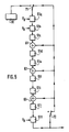
- FIG. 1 shows the principle of this scrambling, by cutting the signal (here AB) of an image line at a point M of random position (at address x) and inversion of the two signal fragments thus formed.
- FIGS. 2, 3a and 3b illustrate the operation of the system on transmission: to an image coding device of conventional type, are added, upstream, two line memories 10 and 20 with random access and two switches 30 and 40 ordered at line frequency. While one of these memories is in the writing phase, with normal writing (fig. 3a) of the current signal from address 0 to the last address n, the other is in the reading phase, but from address x (fig.3b) supplied by a pseudo-random sequence generator 50 to address n, then from address 0 to address x-1. It is this latter signal, as read, which is processed to obtain the signals (a), (b), (c) transmitted in the channels (A), (B), (C).
- FIG. 4 shows an exemplary embodiment of a decoder on reception.
- This decoder comprises, in the example described, an analog-digital converter 401 then a switch 402 with two positions, making it possible to connect the output of the converter either to a first line memory 403 to random access either to a second similar memory 404, for writing the current line.
- a three-position switch 405 is provided at the output of these memories, the output of which is connected to the input of a digital-analog converter 406 intended to deliver the decrypted line signals.
- the switch 405 allows the sending, to the converter 406, either of the output of one of the memories 403 and 404, or of the output of the other of these memories, or directly of the output of the analog converter -digital 401.
- the converters 401 and 406 are controlled at a sampling frequency F e .
- the decoder also includes an intra-frame counter 407 controlling inside each frame the appropriate number of switches 402 and 405 switches. This counter is connected to a pseudo-random sequence generator 408 intended to deliver the information making it possible to define the 'cut-off address x, that is to say the point at which writing begins in that of the two memories 403 or 404 which is in the writing phase.
- the operation of the decoder is symmetrical to that of the encoder: the received signal is written from address x to address n then from address 0 to address x- 1, as in FIG. 3b, and the reading is however carried out from address 0 to address n, as in FIG. 3a.
- the pseudo-random sequence generator 408 receives its loading word either directly from a memory 415 of ROM type for example (connection 409a in solid line) when this word is always the same and well known, or via a conditional access device 410, the connection 409a then being replaced by the connections 409b and 409c in broken lines.
- the decoder finally comprises a write counter 411 and a read counter 412, and these two counters each control alternately one then the other of the two line memories 403 and 404, by means of switches 413 and 414 of which one controls the connection with the other memory, and vice versa. These write and read counters 411 and 412 are controlled at the line frequency F l .
- the format extension or resolution extension signals (a), (b) or (c) can comprise several components, which generally leads to transmission in some of the channels (A), (B) or (C) several signals of different origin.
- a more skilful solution consists in employing a time multiplexing by successively transmitting the different components on the same carrier and / or subcarrier.
- an object of the invention consists in using the same memories to carry out both the decryption and the demultiplexing of the signals transmitted on the same carrier and / or subcarrier.
- FIG. 4 An exemplary embodiment of a decryptor / demultiplexer can be deduced from the diagram in FIG. 4.
- the memories 403 and 404 it suffices to divide the memories 403 and 404 into as many sub-memories as there are different components transmitted on the same carrier or subcarrier, write the signals received in these sub-memories successively according to the order in which they are sent and starting with the respective x addresses, and read the sub-memories simultaneously or in the order required for the reproduction of the signals, starting with the respective addresses 0 of each sub-memory.
- the pseudo-random sequence generator 50 can in particular be of the linear feedback shift register type, the length of the register then being for example 20 cells if it is desired that said generator provide 8 to 10 bits at each line period and that the sequence proceeds without repetition for approximately 5 seconds. Beyond such a duration, the the waiting time for synchronization when switching on the television receiver may indeed seem too long.
- the generator polynomial of degree 20 can be chosen primitive and irreducible so that the sequence is of maximum length (220-1): we will retain for example the polynomial 1 + x3 + x5 + x9 + x20 which corresponds to the pseudo-random sequence generator represented in FIG.
- the 20 cells controlled by the clock frequency F H being referenced 51a to 51t and supplemented by modulo adders 2, 61 to 63, switches 71 and 72 , and a circuit 81 for transferring the generator load word 50.
- the two switches 71 and 72 are in the left position when the generator is loaded from a 20-bit word stored in the circuit 81 and in the right position during the course of the pseudo-random sequence.
Abstract
Description
La présente invention concerne un étage d'émission de signaux correspondant à des images de télévision comprenant des moyens pour transmettre au moins un signal vidéo d'extension d'une caractéristique d'image dans au moins une voie de transmission.The present invention relates to a signal transmission stage corresponding to television images comprising means for transmitting at least one video signal of extension of an image characteristic in at least one transmission channel.
L'invention concerne également un système de transmission d'images de télévision à définition étendue incluant un tel étage d'émission, ainsi qu'un étage de réception pour un tel système de transmission.The invention also relates to a system for transmitting extended definition television images including such a transmission stage, as well as a reception stage for such a transmission system.
En Europe, l'approche haute définition en matière de télévision prévoit une norme dite HDMAC, compatible avec la norme MAC qui sera prochainement utilisée en télédiffusion directe par satellite, et qui pourrait être utilisée également, ultérieurement, en diffusion terrestre. Pendant les premières années de diffusion selon cette norme HDMAC, il se formera un parc de récepteurs de télévision à haute définition qui devront aussi restituer des images émises selon les normes PAL et SECAM.In Europe, the high definition approach to television provides for a so-called HDMAC standard, compatible with the MAC standard which will soon be used in direct broadcasting by satellite, and which could also be used, later, in terrestrial broadcasting. During the first years of broadcasting according to this HDMAC standard, a fleet of high definition television receivers will be formed which will also have to reproduce images emitted according to the PAL and SECAM standards.
En raison de la très grande différence de qualité entre ces dernières images PAL ou SECAM et les images HDMAC, il serait souhaitable, en Europe, que les normes PAL et SECAM voient leur définition étendue, par exemple par des procédés similaires à ceux envisagés aux Etats-Unis dans le cadre de la norme NTSC.Due to the very great difference in quality between the latter PAL or SECAM images and the HDMAC images, it would be desirable, in Europe, for the PAL and SECAM standards to have their definition extended, for example by methods similar to those envisaged in the States -United under the NTSC standard.
Aux Etats-Unis, le FCC a demandé en effet que la télévision à définition étendue, dite EDTV ("Extended Definition Television"), soit compatible avec la norme NTSC existante. Le signal émis pourra alors occuper soit le même canal de 6 MHz de large que la norme NTSC actuelle, soit un canal plus large (9 MHz ou 12 MHz, d'un seul tenant ou en deux canaux séparés), mais il devra être reçu de façon compatible par les récepteurs existants prévus pour la norme NTSC.In the United States, the FCC has requested that extended definition television, called EDTV ("Extended Definition Television"), be compatible with the existing NTSC standard. The transmitted signal can then occupy either the same 6 MHz wide channel as the current NTSC standard, or a wider channel (9 MHz or 12 MHz, in one piece or in two separate channels), but it must be received in a compatible manner by the existing receivers provided for the NTSC standard.
Une norme étendue prévoit, plus précisément, d'ajouter aux signaux transmis actuellement selon la norme existante NTSC, PAL ou SECAM une ou plusieurs des informations suivantes :
- a) des signaux correspondant aux bords de l'image, à droite et à gauche, de façon à agrandir le format de celle-ci de 4/3 à 16/9 ;
- b) des signaux correspondant à l'augmentation de la résolution de l'image dans le sens horizontal ;
- c) des signaux correspondant à l'augmentation de la résolution de l'image dans le sens vertical, et qui peuvent éventuellement être combinés aux signaux (b) pour former une information bidimensionnelle ;
- d) des signaux correspondant à la diffusion des voies son en codage numérique, avec une qualité voisine de celle des disques audio à lecture laser (ou disques compacts).
- a) signals corresponding to the edges of the image, on the right and on the left, so as to enlarge the format of the latter from 4/3 to 16/9;
- b) signals corresponding to the increase in the resolution of the image in the horizontal direction;
- c) signals corresponding to the increase in the resolution of the image in the vertical direction, and which can optionally be combined with the signals (b) to form two-dimensional information;
- d) signals corresponding to the broadcasting of sound channels in digital coding, with a quality close to that of laser-read audio discs (or compact discs).
Pour transmettre cette ou ces informations supplémentaires, la place temporelle laissée libre pendant les périodes de suppression ligne et trame n'est pas suffisante. On compte donc les transmettre également dans la ou les trois voies suivantes :
- (A) sur une porteuse ayant la même fréquence que la porteuse image, mais modulée en quadrature avec celle-ci ;
- (B) sur une sous-porteuse ayant une fréquence voisine des fréquences sous-porteuses qui sont utilisées pour transmettre la chrominance, mais en utilisant un filtrage spatio-temporel (filtre en peigne trame) à l'émission et à la réception de façon à séparer les deux informations ;
- (C) éventuellement, dans un canal de 3 ou 6 MHz de large qui peut être situé juste au-dessus de la bande occupée par les signaux vidéo, ou juste au-dessous, ou complètement séparé, cette troisième voie occupant alors un des canaux, dits tabous, interdits en diffusion terrestre pour éviter les interférences liées au manque de sélectivité des récepteurs (surtout des récepteurs anciens).
- (A) on a carrier having the same frequency as the image carrier, but modulated in quadrature with the latter;
- (B) on a subcarrier having a frequency close to the subcarrier frequencies which are used to transmit the chrominance, but using space-time filtering (frame comb filter) on transmission and on reception so as to separate the two pieces of information;
- (C) possibly, in a 3 or 6 MHz wide channel which may be situated just above the band occupied by the video signals, or just below, or completely separated, this third channel then occupying one of the channels , called taboos, prohibited in terrestrial distribution to avoid interference linked to the lack of selectivity of receptors (especially old receptors).
Dans les récepteurs de nouvelle génération, des méthodes de détection et de filtrage précises (détection synchrone, filtre en peigne, réjection améliorée de la fréquence image, filtre IF plus abrupt) permettront de réduire à un niveau négligeable les interférences entre le signal vidéo classique et les signaux supplémentaires (a), (b), (c), (d) transmis dans les voies (A), (B), (C). Par contre, dans les récepteurs existants, et en particulier dans les modèles les plus anciens, des interférences importantes se produiront, ce qui conduira à une dégradation de la qualité de l'image compatible reçue par ces récepteurs.In new generation receivers, precise detection and filtering methods (synchronous detection, comb filter, improved image frequency rejection, more abrupt IF filter) will make it possible to reduce to a negligible level the interference between the conventional video signal and additional signals (a), (b), (c), (d) transmitted in channels (A), (B), (C). On the other hand, in existing receivers, and in particular in the older models, significant interference will occur, which will lead to a degradation of the quality of the compatible image received by these receivers.
Ces interférences seront les plus gênantes lorsqu'elles correspondront à des parties d'image non corrélées avec l'image vidéo classique reçue, par exemple à des bords, ou lorsqu'elles donneront lieu à d'autres images résultant des interférences entre les canaux interdits et les canaux existants. En effet, il apparaît alors, en superposition avec l'image vidéo classique, une image fantôme (éventuellement réduite à des contours), qui est d'autant plus gênante que les formes et les mouvements qu'elle restitue ne sont pas corrélés avec l'image que l'on veut recevoir.This interference will be the most annoying when it corresponds to image parts not correlated with the conventional video image received, for example at edges, or when they give rise to other images resulting from interference between the prohibited channels. and existing channels. Indeed, it then appears, in superposition with the conventional video image, a ghost image (possibly reduced to contours), which is all the more annoying as the forms and the movements which it restores are not correlated with the image we want to receive.
Les demanderesses se sont alors rendu compte que les signaux (d), transmis sous forme numérique, seront les moins gênants, car ils apparaîtront comme un bruit incohérent vis-à-vis de l'image compatible, et qu'une partie des signaux (b) et (c), celle qui correspond aux informations provenant de la partie de l'image transmise dans le standard d'origine au format 4/3, est complètement corrélée avec l'image compatible et pourra donc ne produire que des interférences peu gênantes si elle est transmise en synchronisme avec cette image compatible. Par contre, les signaux (a) et la partie des signaux (b) et (c) correspondant aux bords de l'image seront toujours particulièrement gênants.The applicants then realized that the signals (d), transmitted in digital form, will be the least annoying, because they will appear as an inconsistent noise vis-à-vis the compatible image, and that part of the signals ( b) and (c), that which corresponds to the information coming from the part of the image transmitted in the original standard in 4/3 format, is completely correlated with the compatible image and may therefore produce only slight interference. troublesome if it is transmitted in synchronism with this compatible image. On the other hand, the signals (a) and the part of the signals (b) and (c) corresponding to the edges of the image will always be particularly troublesome.
Le problème à résoudre est donc de supprimer ou de réduire notablement les perturbations entraînées par l'existence de ces interférences.The problem to be solved is therefore to suppress or significantly reduce the disturbances caused by the existence of this interference.
L'invention concerne, à cet effet, un étage d'émission caractérisé en ce qu'il comprend des moyens de brouillage d'au moins une fraction du ou des signaux vidéo d'extension.To this end, the invention relates to a transmission stage characterized in that it comprises means for scrambling at least a fraction of the extension video signal (s).
Conformément à la solution proposée, l'invention concerne également un étage d'émission caractérisé en ce qu'il comprend des moyens de brouillage horizontal d'au moins l'un desdits signaux (a), (b), (c) et/ou d'au moins une fraction de l'un ou l'autre desdits signaux (a), (b), (c).In accordance with the proposed solution, the invention also relates to a transmission stage characterized in that it comprises means for horizontal jamming of at least one of said signals (a), (b), (c) and / or at least a fraction of either of said signals (a), (b), (c).
Grâce à de telles structures, les signaux (a), (b), (c), ou ceux de ces signaux, ou d'une manière générale la fraction du ou des signaux qui ont été brouillés, prennent une apparence erratique, et ne sont plus corrélés avec l'image d'origine de définition normale. Par suite, les interférences qui peuvent subsister entre ce ou ces signaux et le ou les signaux vidéo d'origine correspondant à l'image normale ont une structure incohérente et deviennent peu perceptibles.Thanks to such structures, the signals (a), (b), (c), or those of these signals, or in general the fraction of the signal or signals which have been scrambled, take on an erratic appearance, and do not are more correlated with the original image of normal definition. Consequently, the interference which may remain between this or these signals and the original video signal or signals corresponding to the normal image has an incoherent structure and becomes hardly perceptible.
Dans le mode préféré de réalisation de l'invention, c'est la totalité des signaux d'extension (a), (b), (c) qui subit le brouillage prévu dans le système. Cependant, il peut être intéressant de réduire la complexité de ce système en diminuant la capacité mémoire nécessaire. Dans ce cas, on exclut de l'opération de brouillage une fraction des signaux d'extension, par exemple en exemptant du brouillage la fraction des signaux (b) et (c) qui correspond au milieu de l'image, c'est-à-dire à l'image normale sans extension de définition.In the preferred embodiment of the invention, it is the totality of the extension signals (a), (b), (c) which undergoes the interference provided for in the system. However, it may be interesting to reduce the complexity of this system by reducing the memory capacity required. In this case, a fraction of the extension signals is excluded from the scrambling operation, for example by exempting from scrambling the fraction of the signals (b) and (c) which corresponds to the middle of the image, ie ie normal image without definition extension.
Un procédé de brouillage particulièrement bien adapté au cas présent consiste à opérer sur chaque ligne une permutation circulaire à partir d'une adresse variable x définie par un générateur de séquences pseudoaléatoires. L'image devient en effet complètement décorrélée dans le sens horizontal, avec une disparition complète des structures et des contours initiaux. Dès lors, toute interférence entre l'un ou l'autre des signaux (a), (b), (c) et l'image compatible apparaît comme un bruit dans l'image reçue, ce qui constitue une perturbation dégradant cette image de façon nettement moins perceptible qu'une perturbation consécutive à des interférences dues à une image fantôme.A scrambling method particularly well suited to the present case consists in operating on each line a circular permutation from a variable address x defined by a generator of pseudo-random sequences. The image indeed becomes completely uncorrelated in the horizontal direction, with a complete disappearance of the structures and initial contours. Consequently, any interference between one or other of the signals (a), (b), (c) and the compatible image appears as noise in the received image, which constitutes a disturbance degrading this image of significantly less noticeable than a disturbance due to interference due to a ghost image.
De préférence, l'adresse x du point de coupure du signal sur chaque ligne est donnée par un mot pseudoaléatoire de p bits, délivré par le générateur de séquences pseudoaléatoires fonctionnant à une fréquence au moins égale à p fois la fréquence ligne. Si par exemple cette fréquence est égale à 8 fois la fréquence ligne, on disposera, au cours de chaque période de ligne, d'un mot pseudoaléatoire de 8 bits permettant de choisir l'adresse du point de coupure du signal parmi 256 positions distinctes x₀ à xn-1. Pour des raisons de simplicité, on aura intérêt à ce que cette fréquence de fonctionnement soit égale à p fois, ou à un multiple de p fois, ladite fréquence ligne.Preferably, the address x of the signal cut-off point on each line is given by a pseudo-random word of p bits, delivered by the generator of pseudo-random sequences operating at a frequency at least equal to p times the line frequency. If for example this frequency is equal to 8 times the line frequency, we will have, during each line period, a pseudo-random word of 8 bits allowing to choose the address of the signal cut-off point among 256 distinct positions x₀ at x n-1 . For reasons of simplicity, it will be advantageous for this operating frequency to be equal to p times, or to a multiple of p times, said line frequency.
Le brouillage par permutation circulaire dans chaque ligne à partir d'une adresse pseudoaléatoire ne décorrèle l'image que dans le sens horizontal. En d'autres termes, ce brouillage ne transforme le spectre de l'image en un spectre de bruit que pour les fréquences supérieures à la demi-fréquence ligne, soit 8 kHz environ. Cela peut être insuffisant lorsque l'image comprend des bandes horizontales fortement contrastées, par exemple un horizon séparant la terre d'un ciel très lumineux.Interference by circular permutation in each line from a pseudo-random address decorrelates the image only in the horizontal direction. In other words, this interference only transforms the spectrum of the image into a noise spectrum for frequencies above the line half-frequency, ie around 8 kHz. This may be insufficient when the image includes highly contrasted horizontal bands, for example a horizon separating the earth from a very bright sky.
Pour améliorer l'efficacité du brouillage dans de telles situations, on peut rendre celui-ci plus complexe en effectuant un brassage pseudoaléatoire de tout ou partie des lignes entre elles. On peut utiliser, par exemple, pour le brassage, une permutation circulaire à l'intérieur d'un groupe de lignes consécutives, en prévoyant alors la capacité mémoire correspondante qui permet d'effectuer l'écriture et la lecture de ce groupe de lignes. L'adresse variable y de la ligne à partir de laquelle se fait la modification de l'ordre de transmission des lignes peut être obtenue sous la forme d'un nombre ℓ de bits issus d'une séquence pseudoaléatoire, tel que 2ℓ soit inférieur ou égal au nombre L de lignes.To improve the effectiveness of interference in such situations, it can be made more complex by performing pseudo-random mixing of all or part of the lines between them. One can use, for example, for shuffling, a circular permutation inside a group of consecutive lines, while providing for the corresponding memory capacity which makes it possible to write and read this group of lines. The variable address y of the line to from which the modification of the transmission order of the lines is made can be obtained in the form of a number ℓ of bits originating from a pseudo-random sequence, such that 2 ℓ is less than or equal to the number L of lines.
Les ℓ bits peuvent être issus du même générateur de séquences pseudoaléatoires que celui qui fournit les p bits déterminant l'adresse de la coupure dans chaque ligne. On peut, par exemple, ne pas changer la fréquence de fonctionnement du générateur et choisir les ℓ bits de l'adresse y de brassage parmi les L x p bits fournis par le générateur en L périodes lignes. On peut également faire fonctionner le générateur à une fréquence plus élevée, toujours multiple de la fréquence ligne, par exemple à une fréquence égale à (p+1) fois la fréquence ligne, et utiliser d'une part p bits toutes les périodes lignes pour déterminer les adresses de coupure x, et d'autre part ℓ bits choisis toutes les L périodes lignes parmi les L bits supplémentaires fournis par le générateur et non utilisés par les adresses x, pour déterminer l'adresse y de début de modification de l'ordre de transmission des lignes.The ℓ bits can come from the same pseudo-random sequence generator as that which provides the p bits determining the address of the cut in each line. It is possible, for example, not to change the operating frequency of the generator and to choose the ℓ bits of the patching address y from among the L x p bits supplied by the generator in L line periods. It is also possible to operate the generator at a higher frequency, always a multiple of the line frequency, for example at a frequency equal to (p + 1) times the line frequency, and to use on the one hand p bits all the line periods for determine the cut-off addresses x, and on the other hand ℓ bits chosen every L line periods among the L additional bits supplied by the generator and not used by the addresses x, to determine the address y at the start of modification of the line transmission order.
Pour des raisons de simplicité du système, le générateur de séquences pseudoaléatoires peut être synchronisé avec la fréquence image ou trame (25, 30, 50 ou 60 Hz), mais l'interférence parasite apparaîtra alors comme un bruit spatial à structure temporelle fixe et sera par conséquent plus perceptible. Pour limiter ou supprimer ce défaut résiduel, il est donc préférable de prévoir le déroulement de la séquence pseudoaléatoire sur un nombre M de trames important (plus de cent, par exemple), ce qui donne à l'interférence parasite éventuelle une structure de bruit à la fois spatiale et temporelle. Il convient alors d'ajouter, dans la transmission, à destination du générateur de séquences pseudoaléatoires situé à la réception, un signal de synchronisation qui peut être facilement introduit dans une période de suppression trame.For reasons of simplicity of the system, the generator of pseudo-random sequences can be synchronized with the image or frame frequency (25, 30, 50 or 60 Hz), but the parasitic interference will then appear as a spatial noise with fixed temporal structure and will be therefore more noticeable. To limit or eliminate this residual defect, it is therefore preferable to provide for the unfolding of the pseudo-random sequence over a large number M of frames (more than one hundred, for example), which gives the possible parasitic interference a noise structure to both spatial and temporal. It is then advisable to add, in the transmission, intended for the generator of pseudo-random sequences situated at the reception, a synchronization signal which can be easily introduced in a frame blanking period.
Le brouillage décrit jusqu'à présent est destiné essentiellement à réduire ou supprimer la gêne due aux interférences. Dans ce cas, à chaque instant de synchronisation des générateurs de séquences pseudoaléatoires, on utilise un même mot de chargement, tout à fait connu, à l'émission et à la réception. On peut également rendre conditionnel l'accès au déchiffrement des signaux d'extension de définition. Il suffit pour cela que le mot de chargement des générateurs change périodiquement et ne soit communiqué au récepteur que par une procédure d'accès conditionnel. On peut ainsi réserver aux seuls abonnés ayant acquitté une redevance ou obtenu une autorisation le service supplémentaire constitué par l'extension du format et l'amélioration de la définition de l'image.The interference described so far is intended basically to reduce or remove the annoyance from interference. In this case, at each moment of synchronization of the generators of pseudo-random sequences, the same loading word, entirely known, is used on transmission and on reception. Access to the decryption of definition extension signals can also be made conditional. It suffices for this that the generator loading word changes periodically and is communicated to the receiver only by a conditional access procedure. It is thus possible to reserve only for subscribers who have paid a fee or obtained an authorization the additional service constituted by the extension of the format and the improvement of the definition of the image.
On peut encore remarquer que le brouillage par coupure et permutation circulaire des signaux de ligne apporte sur l'ensemble émission et réception un retard égal à deux périodes de ligne au signal qui a subi ce brouillage, par rapport au signal non brouillé. De même, si l'on ajoute un brouillage par brassage vertical de L lignes au brouillage horizontal par coupure et permutation circulaire, c'est un retard égal à 2L périodes de ligne que l'on obtient. Afin de simplifier au maximum le décodeur du récepteur à définition étendue, il est donc judicieux de retarder dans le codeur situé à l'émission tous les signaux non brouillés, et en particulier le signal compatible, d'un délai égal à 2L périodes de ligne. On utilisera, par exemple, 2L mémoires de ligne, L pouvant bien entendu être par exemple égal à 1, ce qui correspond au cas précédent d'absence de brassage vertical des lignes.It can also be noted that the interference by cutting and circular permutation of the line signals brings a delay equal to two line periods on the transmission and reception assembly to the signal which has undergone this interference, relative to the non-interference signal. Similarly, if we add interference by vertical mixing of L lines to horizontal interference by cutting and circular permutation, it is a delay equal to 2L line periods that we obtain. In order to simplify the decoder of the extended definition receiver as much as possible, it is therefore a good idea to delay in the encoder located at transmission all the unscrambled signals, and in particular the compatible signal, by a delay equal to 2L line periods . We will use, for example, 2L line memories, L which can of course be for example equal to 1, which corresponds to the previous case of absence of vertical stirring of the lines.
Conformément à l'invention, lorsqu'au moins un signal vidéo d'extension d'une caractéristique d'image a été transmis après brouillage dans un étage d'émission tel que défini plus haut, et notamment dans un étage d'émission pour un système de transmission d'images dans lesquels le ou les signaux vidéo d'extension ont été transmis comme indiqué ci-dessus, l'étage de réception est alors tel que celui-ci, équipé de moyens de réception dudit ou desdits signaux, comprend également des moyens de déchiffrement d'au moins une fraction dudit ou desdits signaux d'extension.According to the invention, when at least one video signal for extending an image characteristic has been transmitted after jamming in a transmission stage as defined above, and in particular in a transmission stage for a image transmission system in which the extension video signal or signals have been transmitted as indicated above, the reception stage is then such that the latter, equipped with means for reception of said signal or signals, also comprises means for deciphering at least one fraction of said extension signal (s).
Dans un mode de réalisation préférentiel, cet étage de réception, destiné à un système de transmission d'images de télévision dans lequel un ou des signaux vidéo d'extension du format des images et d'extension des définitions horizontale et verticale desdites images sont émis et transmis en superposition des signaux vidéo classiques correspondant aux images d'origine, lesdits signaux d'extension ayant subi avant transmission une permutation circulaire à partir d'un point de coupure défini pour chaque ligne à l'aide d'un générateur de séquences pseudoaléatoires, est plus particulièrement caractérisé en ce qu'il comprend un dispositif de décodage comprenant lui-même :
- (a) une première et une deuxième mémoire placées en parallèle pour l'écriture d'une ligne dans l'une de ces mémoires pendant la lecture de la ligne précédemment écrite dans l'autre et réciproquement, les signaux d'extension reçus étant inscrits à partir de l'adresse x correspondant audit point de coupure propre à chaque ligne, puis en revenant à l'adresse correspondant au début du signal de ligne lorsque la fin de ligne a été atteinte, et en continuant ainsi jusqu'à atteindre à nouveau ladite adresse x ;
- (b) un compteur d'écriture et un compteur de lecture, commandés à la fréquence ligne ;
- (c) un module de déchiffrement comprenant un circuit de contrôle d'accès et un générateur de séquences pseudoaléatoires et destiné à commander ledit compteur d'écriture.
- (a) a first and a second memory placed in parallel for writing a line in one of these memories during the reading of the line previously written in the other and vice versa, the received extension signals being recorded from the address x corresponding to said cut-off point specific to each line, then returning to the address corresponding to the start of the line signal when the end of line has been reached, and thus continuing until reaching again said address x;
- (b) a write counter and a read counter, controlled at the line frequency;
- (c) a decryption module comprising an access control circuit and a generator of pseudo-random sequences and intended to control said write counter.
Les particularités et avantages de l'invention pourront aussi, éventuellement, apparaître de façon plus détaillée dans la description qui suit et dans les dessins annexés, donnés à titre d'exemple non limitatif et dans lesquels :
- - la figure 1 montre le principe de brouillage du signal d'une ligne d'image ;
- - les figures 2, 3a, 3b illustrent le fonctionnement du système à l'émission ;
- - la figure 4 montre un exemple de réalisation d'un décodeur selon l'invention ;
- - la figure 5 montre un exemple de générateur de séquences pseudoaléatoires conduisant à un temps maximum d'attente de synchronisation de 5 secondes environ à la mise en route du récepteur.
- - Figure 1 shows the principle of scrambling the signal of an image line;
- - Figures 2, 3a, 3b illustrate the operation of the system on transmission;
- - Figure 4 shows an embodiment of a decoder according to the invention;
- FIG. 5 shows an example of a pseudo-random sequence generator leading to a maximum synchronization waiting time of approximately 5 seconds when the receiver is started up.
On a vu ci-dessus que le problème à résoudre était celui de la présence de perturbations dues à la cohérence des interférences se produisant avec les signaux utiles. Pour donner à ces interférences une structure incohérente, le brouillage de type permutation circulaire appliqué à chaque ligne, tel que préconisé par l'UER (Union Européenne de Radiodiffusion) dans ses documents SPB 284 et SPB 352 pour la diffusion de signaux de type MAC, a été adopté.We have seen above that the problem to be solved was that of the presence of disturbances due to the coherence of the interference occurring with the useful signals. To give these interferences an incoherent structure, interference of the circular permutation type applied to each line, as recommended by the EBU (European Broadcasting Union) in its documents SPB 284 and SPB 352 for the broadcasting of MAC type signals, has been adopted.
La figure 1 montre le principe de ce brouillage, par coupure du signal (ici AB) d'une ligne d'image en un point M de position aléatoire (à l'adresse x) et interversion des deux fragments de signal ainsi constitués. Les figures 2, 3a et 3b illustrent le fonctionnement du système à l'émission : à un dispositif de codage d'image de type classique, sont ajoutés, en amont, deux mémoires de ligne 10 et 20 à accès aléatoire et deux commutateurs 30 et 40 commandés à la fréquence ligne. Pendant qu'une de ces mémoires est en phase d'écriture, avec inscription normale (fig.3a) du signal courant à partir de l'adresse 0 jusqu'à la dernière adresse n, l'autre est en phase de lecture, mais à partir de l'adresse x (fig.3b) fournie par un générateur de séquences pseudoaléatoires 50 jusqu'à l'adresse n, puis de l'adresse 0 à l'adresse x-1. C'est ce dernier signal, tel que lu, qui est traité pour obtenir les signaux (a), (b), (c) transmis dans les voies (A), (B), (C).FIG. 1 shows the principle of this scrambling, by cutting the signal (here AB) of an image line at a point M of random position (at address x) and inversion of the two signal fragments thus formed. FIGS. 2, 3a and 3b illustrate the operation of the system on transmission: to an image coding device of conventional type, are added, upstream, two
La figure 4 montre un exemple de réalisation d'un décodeur à la réception. Ce décodeur comprend, dans l'exemple décrit, un convertisseur analogique-numérique 401 puis un commutateur 402 à deux positions, permettant de relier la sortie du convertisseur soit à une première mémoire de ligne 403 à accès aléatoire soit à une deuxième mémoire 404 similaire, pour l'écriture de la ligne courante. En sortie de ces mémoires est prévu un commutateur 405 à trois positions dont la sortie est reliée à l'entrée d'un convertisseur numérique-analogique 406 destiné à délivrer les signaux de ligne déchiffrés. Selon sa position, le commutateur 405 permet l'envoi, vers le convertisseur 406, soit de la sortie d'une des mémoires 403 et 404, soit de la sortie de l'autre de ces mémoires, soit directement de la sortie du convertisseur analogique-numérique 401. Les convertisseurs 401 et 406 sont commandés à une fréquence d'échantillonnage Fe.FIG. 4 shows an exemplary embodiment of a decoder on reception. This decoder comprises, in the example described, an analog-
Le décodeur comprend également un compteur intra-trame 407 commandant à l'intérieur de chaque trame le nombre approprié de basculements des commutateurs 402 et 405. Ce compteur est relié à un générateur de séquences pseudoaléatoires 408 destiné à délivrer l'information permettant de définir l'adresse x de coupure, c'est-à-dire le point de début de l'écriture dans celle des deux mémoires 403 ou 404 qui est en phase d'écriture. En effet, le fonctionnement du décodeur est symétrique de celui du codeur : l'écriture du signal reçu est effectuée à partir de l'adresse x jusqu'à l'adresse n puis de l'adresse 0 jusqu'à l'adresse x-1, comme sur la figure 3b, et la lecture est par contre effectuée de l'adresse 0 à l'adresse n, comme sur la figure 3a. Le générateur de séquences pseudoaléatoires 408 reçoit son mot de chargement soit en provenance directe d'une mémoire 415 de type ROM par exemple (connexion 409a en trait continu) lorsque ce mot est toujours le même et bien connu, soit par l'intermédiaire d'un dispositif d'accès conditionnel 410, la connexion 409a étant alors remplacée par les connexions 409b et 409c en trait discontinu. Le décodeur comprend enfin un compteur d'écriture 411 et un compteur de lecture 412, et ces deux compteurs commandent chacun alternativement l'une puis l'autre des deux mémoires de ligne 403 et 404, par l'intermédiaire de commutateurs 413 et 414 dont l'un commande la liaison avec l'autre mémoire, et réciproquement. Ces compteurs d'écriture et de lecture 411 et 412 sont commandés à la fréquence ligne Fℓ.The decoder also includes an
Les signaux d'extension de format ou d'extension de résolution (a), (b) ou (c) peuvent comprendre plusieurs composantes, ce qui conduit généralement à transmettre dans certaines des voies (A), (B) ou (C) plusieurs signaux d'origine différente. On peut employer pour cela un multiplex fréquentiel en utilisant, par exemple, plusieurs porteuses dans la voie (C) ou plusieurs sous-porteuses dans la voie (B), ce qui entraîne, en général, un problème de filtrage pour séparer efficacement les différentes composantes transmises. Une solution plus habile consiste à employer un multiplexage temporel en transmettant successivement les différentes composantes sur la même porteuse et/ou sous-porteuse. Dans ce cas un objet de l'invention consiste à utiliser les mêmes mémoires pour effectuer à la fois le déchiffrement et le démultiplexage des signaux transmis sur la même porteuse et/ou sous-porteuse.The format extension or resolution extension signals (a), (b) or (c) can comprise several components, which generally leads to transmission in some of the channels (A), (B) or (C) several signals of different origin. One can use for this a frequency multiplex by using, for example, several carriers in the channel (C) or several subcarriers in the channel (B), which involves, in general, a problem of filtering to effectively separate the different transmitted components. A more skilful solution consists in employing a time multiplexing by successively transmitting the different components on the same carrier and / or subcarrier. In this case, an object of the invention consists in using the same memories to carry out both the decryption and the demultiplexing of the signals transmitted on the same carrier and / or subcarrier.
Un exemple de réalisation d'un déchiffreur/démultiplexeur peut être déduit du schéma de la figure 4. Il suffit en effet, dans ce schéma, de diviser les mémoires 403 et 404 en autant de sous-mémoires qu'il y a de composantes différentes transmises sur la même porteuse ou sous-porteuse, d'effectuer l'écriture des signaux reçus dans ces sous-mémoires successivement suivant l'ordre dans lequel il sont envoyés et en commençant par les adresses x respectives, et d'effectuer la lecture des sous-mémoires simultanément ou dans l'ordre requis pour la restitution des signaux, en commençant par les adresses 0 respectives de chaque sous-mémoire. Ceci conduit, en général, à utiliser des fréquences d'écriture et de lecture des mémoires différentes, comme il est habituel de le faire lorsqu'on effectue le décodage de signaux ayant subi un multiplexage temporel, comme les signaux MAC par exemple.An exemplary embodiment of a decryptor / demultiplexer can be deduced from the diagram in FIG. 4. In this diagram, it suffices to divide the
Le générateur de séquences pseudoaléatoires 50 peut être notamment du type à registre à décalage à rebouclage linéaire (en anglais, linear feedback shift register), la longueur du registre étant alors par exemple de 20 cellules si l'on veut que ledit générateur fournisse 8 à 10 bits à chaque période de ligne et que la séquence se déroule sans répétition pendant environ 5 secondes. Au-delà d'une telle durée, le temps d'attente de la synchronisation à la mise en route du récepteur de télévision pourrait, en effet, paraître trop long. Dans cet exemple, qui n'est cependant pas limitatif, le polynôme générateur de degré 20 peut être choisi primitif et irréductible pour que la séquence soit de longueur maximale (2²⁰-1) : on retiendra par exemple le polynôme 1 + x³ + x⁵ + x⁹ + x²⁰ qui correspond au générateur de séquences pseudoaléatoires représenté sur la figure 5, les 20 cellules commandées par la fréquence d'horloge FH étant référencées 51a à 51t et complétées par des additionneurs modulo 2, 61 à 63, des commutateurs 71 et 72, et un circuit 81 de transfert du mot de chargement du générateur 50. Les deux commutateurs 71 et 72 sont en position gauche lors du chargement du générateur à partir d'un mot de 20 bits mis en mémoire dans le circuit 81 et en position droite lors du déroulement de la séquence pseudoaléatoire.The
Claims (26)
Applications Claiming Priority (2)
| Application Number | Priority Date | Filing Date | Title |
|---|---|---|---|
| FR8901020 | 1989-01-27 | ||
| FR8901020A FR2642597A1 (en) | 1989-01-27 | 1989-01-27 | TRANSMISSION STAGE FOR EXTENDED DEFINITION TELEVISION IMAGE TRANSMISSION SYSTEM, TRANSMISSION SYSTEM INCLUDING SUCH STAGE, AND RECEPTION STAGE FOR SUCH A SYSTEM |
Publications (2)
| Publication Number | Publication Date |
|---|---|
| EP0380181A1 true EP0380181A1 (en) | 1990-08-01 |
| EP0380181B1 EP0380181B1 (en) | 1994-08-03 |
Family
ID=9378172
Family Applications (1)
| Application Number | Title | Priority Date | Filing Date |
|---|---|---|---|
| EP90200165A Expired - Lifetime EP0380181B1 (en) | 1989-01-27 | 1990-01-23 | Ermitter stage for an extended definition television picture transmission system, transmission system including such a stage, and a reception stage for such a system |
Country Status (5)
| Country | Link |
|---|---|
| US (1) | US5046091A (en) |
| EP (1) | EP0380181B1 (en) |
| JP (1) | JPH02238789A (en) |
| DE (1) | DE69011143T2 (en) |
| FR (1) | FR2642597A1 (en) |
Cited By (1)
| Publication number | Priority date | Publication date | Assignee | Title |
|---|---|---|---|---|
| EP0620690A1 (en) * | 1993-04-15 | 1994-10-19 | Matsushita Electric Industrial Co., Ltd. | Video signal encrypting apparatus |
Families Citing this family (2)
| Publication number | Priority date | Publication date | Assignee | Title |
|---|---|---|---|---|
| US5239582A (en) * | 1991-11-08 | 1993-08-24 | Macrovision Corporation | Ramp generation for preventing transitions with infinite short rise time in a video scrambling system |
| FR3004611B1 (en) * | 2013-04-16 | 2015-05-15 | Morpho | METHOD FOR MANAGING MEMORY RESOURCES OF A SECURITY DEVICE, SUCH AS A CHIP CARD, AND SECURITY DEVICE IMPLEMENTING SAID METHOD. |
Citations (2)
| Publication number | Priority date | Publication date | Assignee | Title |
|---|---|---|---|---|
| EP0103339A1 (en) * | 1982-09-14 | 1984-03-21 | La Radiotechnique Portenseigne | Television picture scrambling method, and descrambling apparatus therefor |
| EP0279625A2 (en) * | 1987-02-16 | 1988-08-24 | British Broadcasting Corporation | Signal transmission system |
Family Cites Families (1)
| Publication number | Priority date | Publication date | Assignee | Title |
|---|---|---|---|---|
| US4908697A (en) * | 1987-07-24 | 1990-03-13 | North American Philips Corporation | Two-line mac high definition television system |
-
1989
- 1989-01-27 FR FR8901020A patent/FR2642597A1/en not_active Withdrawn
-
1990
- 1990-01-23 EP EP90200165A patent/EP0380181B1/en not_active Expired - Lifetime
- 1990-01-23 DE DE69011143T patent/DE69011143T2/en not_active Expired - Fee Related
- 1990-01-26 US US07/471,172 patent/US5046091A/en not_active Expired - Fee Related
- 1990-01-29 JP JP2016287A patent/JPH02238789A/en active Pending
Patent Citations (2)
| Publication number | Priority date | Publication date | Assignee | Title |
|---|---|---|---|---|
| EP0103339A1 (en) * | 1982-09-14 | 1984-03-21 | La Radiotechnique Portenseigne | Television picture scrambling method, and descrambling apparatus therefor |
| EP0279625A2 (en) * | 1987-02-16 | 1988-08-24 | British Broadcasting Corporation | Signal transmission system |
Non-Patent Citations (2)
| Title |
|---|
| IEEE TRANSACTIONS ON BROADCASTING, vol. BC-33, no. 4 décembre 1987, pages 116-123, IEEE, New York, US; M.A. ISNARDI et al.: "Encoding for compatibility and recoverability in the ACTV system" * |
| TECH. 3258-F, octobre 1986, pages 67-79, Union Européenne de Radiodiffusion, Bruxelles, BE; G.T. WATERS: "Spécification des systèmes de la famille MAC/paquets", partie 2, section 6: "Embrouillage de l'image" * |
Cited By (2)
| Publication number | Priority date | Publication date | Assignee | Title |
|---|---|---|---|---|
| EP0620690A1 (en) * | 1993-04-15 | 1994-10-19 | Matsushita Electric Industrial Co., Ltd. | Video signal encrypting apparatus |
| US5488658A (en) * | 1993-04-15 | 1996-01-30 | Matsushita Electric Industrial Co., Ltd. | Video signal scrambling and descrambling apparatus |
Also Published As
| Publication number | Publication date |
|---|---|
| EP0380181B1 (en) | 1994-08-03 |
| JPH02238789A (en) | 1990-09-21 |
| DE69011143T2 (en) | 1995-03-02 |
| DE69011143D1 (en) | 1994-09-08 |
| US5046091A (en) | 1991-09-03 |
| FR2642597A1 (en) | 1990-08-03 |
Similar Documents
| Publication | Publication Date | Title |
|---|---|---|
| FR2718594A1 (en) | Method for broadcasting programs with progressive conditional access and with separation of the information flow. | |
| EP0330279A1 (en) | Device for the space-time sub-sampling of digital video signals representative of a sequence of interlaced or sequential pictures, system for the transmission of high definition television pictures including such a device, and broadcasting and receiving stages for such a system | |
| BE1007882A3 (en) | Method for broadcasting conditional access program enabling gradual process of access access and programs as a progressive. | |
| EP0583202B1 (en) | Methods for broadcasting and receiving of conditional access programs with reduced program switching times | |
| EP0103339A1 (en) | Television picture scrambling method, and descrambling apparatus therefor | |
| FR2565754A1 (en) | TELEVISION TRANSMISSION SYSTEM | |
| FR2543387A1 (en) | ||
| EP0119945A1 (en) | Television picture scrambling and unscrambling method and apparatus | |
| EP0380181B1 (en) | Ermitter stage for an extended definition television picture transmission system, transmission system including such a stage, and a reception stage for such a system | |
| EP0196681B1 (en) | Method and apparatuses for descrambling or scrambling applied to the mac television standard | |
| EP0126495B1 (en) | Descrambler for television pictures scrambled by circular permutation | |
| EP0188030A2 (en) | Method of coding and decoding of audio information and apparatus for carrying out the method | |
| EP0158383A1 (en) | Device for deciphering and decoding television pictures coded according to the MAC standard and scrambled by application of circular permutations to the video signals | |
| EP0365090A1 (en) | Device for doubling the sequential rate of television signals, and television picture decoder comprising such a device | |
| EP0338915B1 (en) | Method for transmitting television programmes of the mac/packet type, and device using such a method | |
| EP0194186B1 (en) | Method for data transmission by insertion into an analogous speech signal, and device for carrying out this method | |
| FR2549332A1 (en) | Method and device for preventing the unauthorised recording of a television video signal. | |
| EP0395507B1 (en) | Transmission and reception system for the transmission of moving colour pictures and sound through independent channels | |
| FR2700911A1 (en) | Method and device for channel coding/decoding of a high-definition digital television signal broadcast by satellite | |
| FR2656189A1 (en) | HIGH DEFINITION SIGNAL SYSTEM AND DECODER OF THE MAC / PACKET FAMILY, COMPATIBLE WITH BROADBAND AND NARROWBAND TRANSMISSION. | |
| EP0338594B1 (en) | Television signal descrambling device | |
| FR2690805A1 (en) | Device for inserting digital television programs on a transmission or broadcasting channel and device for receiving such programs. | |
| WO2003107655A1 (en) | Method and interface for communication between a server and at least one receiver terminal | |
| FR2590432A1 (en) | Method and device for decoding and deciphering signals having undergone a MAC type coding and ciphering by cyclic permutation about one or two cutoff points, and coding and ciphering device operating in similar fashion | |
| FR2641659A1 (en) | Process for transmitting supplementary analog signals in a television composite video signal and device for implementing this process |
Legal Events
| Date | Code | Title | Description |
|---|---|---|---|
| PUAI | Public reference made under article 153(3) epc to a published international application that has entered the european phase |
Free format text: ORIGINAL CODE: 0009012 |
|
| AK | Designated contracting states |
Kind code of ref document: A1 Designated state(s): DE FR GB |
|
| 17P | Request for examination filed |
Effective date: 19910130 |
|
| 17Q | First examination report despatched |
Effective date: 19930128 |
|
| GRAA | (expected) grant |
Free format text: ORIGINAL CODE: 0009210 |
|
| AK | Designated contracting states |
Kind code of ref document: B1 Designated state(s): DE FR GB |
|
| REF | Corresponds to: |
Ref document number: 69011143 Country of ref document: DE Date of ref document: 19940908 |
|
| GBT | Gb: translation of ep patent filed (gb section 77(6)(a)/1977) |
Effective date: 19941026 |
|
| PG25 | Lapsed in a contracting state [announced via postgrant information from national office to epo] |
Ref country code: GB Effective date: 19950123 |
|
| PLBE | No opposition filed within time limit |
Free format text: ORIGINAL CODE: 0009261 |
|
| STAA | Information on the status of an ep patent application or granted ep patent |
Free format text: STATUS: NO OPPOSITION FILED WITHIN TIME LIMIT |
|
| 26N | No opposition filed | ||
| GBPC | Gb: european patent ceased through non-payment of renewal fee |
Effective date: 19950123 |
|
| PG25 | Lapsed in a contracting state [announced via postgrant information from national office to epo] |
Ref country code: FR Effective date: 19950929 |
|
| PG25 | Lapsed in a contracting state [announced via postgrant information from national office to epo] |
Ref country code: DE Effective date: 19951003 |
|
| REG | Reference to a national code |
Ref country code: FR Ref legal event code: ST |