EP0529834A1 - Recorded information reproducing device - Google Patents
Recorded information reproducing device Download PDFInfo
- Publication number
- EP0529834A1 EP0529834A1 EP92307128A EP92307128A EP0529834A1 EP 0529834 A1 EP0529834 A1 EP 0529834A1 EP 92307128 A EP92307128 A EP 92307128A EP 92307128 A EP92307128 A EP 92307128A EP 0529834 A1 EP0529834 A1 EP 0529834A1
- Authority
- EP
- European Patent Office
- Prior art keywords
- information
- control
- data
- music
- recorded
- Prior art date
- Legal status (The legal status is an assumption and is not a legal conclusion. Google has not performed a legal analysis and makes no representation as to the accuracy of the status listed.)
- Granted
Links
- 238000013500 data storage Methods 0.000 claims abstract description 6
- 230000005236 sound signal Effects 0.000 claims description 17
- 230000001755 vocal effect Effects 0.000 claims description 9
- 238000010586 diagram Methods 0.000 description 9
- 230000001360 synchronised effect Effects 0.000 description 5
- 230000003321 amplification Effects 0.000 description 4
- 238000003199 nucleic acid amplification method Methods 0.000 description 4
- 230000033764 rhythmic process Effects 0.000 description 4
- 239000004065 semiconductor Substances 0.000 description 4
- 239000000284 extract Substances 0.000 description 3
- 238000005286 illumination Methods 0.000 description 3
- 230000003287 optical effect Effects 0.000 description 3
- 238000005070 sampling Methods 0.000 description 3
- 239000003086 colorant Substances 0.000 description 2
- 230000000694 effects Effects 0.000 description 2
- 238000000034 method Methods 0.000 description 2
- 230000003252 repetitive effect Effects 0.000 description 2
- 241001342895 Chorus Species 0.000 description 1
- 230000003044 adaptive effect Effects 0.000 description 1
- 239000004020 conductor Substances 0.000 description 1
- 238000010276 construction Methods 0.000 description 1
- HAORKNGNJCEJBX-UHFFFAOYSA-N cyprodinil Chemical compound N=1C(C)=CC(C2CC2)=NC=1NC1=CC=CC=C1 HAORKNGNJCEJBX-UHFFFAOYSA-N 0.000 description 1
- 230000006870 function Effects 0.000 description 1
- 238000002360 preparation method Methods 0.000 description 1
Images


Classifications
-
- H—ELECTRICITY
- H04—ELECTRIC COMMUNICATION TECHNIQUE
- H04N—PICTORIAL COMMUNICATION, e.g. TELEVISION
- H04N9/00—Details of colour television systems
- H04N9/79—Processing of colour television signals in connection with recording
- H04N9/80—Transformation of the television signal for recording, e.g. modulation, frequency changing; Inverse transformation for playback
- H04N9/802—Transformation of the television signal for recording, e.g. modulation, frequency changing; Inverse transformation for playback involving processing of the sound signal
-
- G—PHYSICS
- G10—MUSICAL INSTRUMENTS; ACOUSTICS
- G10H—ELECTROPHONIC MUSICAL INSTRUMENTS; INSTRUMENTS IN WHICH THE TONES ARE GENERATED BY ELECTROMECHANICAL MEANS OR ELECTRONIC GENERATORS, OR IN WHICH THE TONES ARE SYNTHESISED FROM A DATA STORE
- G10H1/00—Details of electrophonic musical instruments
- G10H1/36—Accompaniment arrangements
- G10H1/361—Recording/reproducing of accompaniment for use with an external source, e.g. karaoke systems
- G10H1/363—Recording/reproducing of accompaniment for use with an external source, e.g. karaoke systems using optical disks, e.g. CD, CD-ROM, to store accompaniment information in digital form
-
- G—PHYSICS
- G11—INFORMATION STORAGE
- G11B—INFORMATION STORAGE BASED ON RELATIVE MOVEMENT BETWEEN RECORD CARRIER AND TRANSDUCER
- G11B20/00—Signal processing not specific to the method of recording or reproducing; Circuits therefor
-
- G—PHYSICS
- G11—INFORMATION STORAGE
- G11B—INFORMATION STORAGE BASED ON RELATIVE MOVEMENT BETWEEN RECORD CARRIER AND TRANSDUCER
- G11B27/00—Editing; Indexing; Addressing; Timing or synchronising; Monitoring; Measuring tape travel
- G11B27/10—Indexing; Addressing; Timing or synchronising; Measuring tape travel
- G11B27/102—Programmed access in sequence to addressed parts of tracks of operating record carriers
- G11B27/105—Programmed access in sequence to addressed parts of tracks of operating record carriers of operating discs
-
- G—PHYSICS
- G11—INFORMATION STORAGE
- G11B—INFORMATION STORAGE BASED ON RELATIVE MOVEMENT BETWEEN RECORD CARRIER AND TRANSDUCER
- G11B27/00—Editing; Indexing; Addressing; Timing or synchronising; Monitoring; Measuring tape travel
- G11B27/10—Indexing; Addressing; Timing or synchronising; Measuring tape travel
- G11B27/19—Indexing; Addressing; Timing or synchronising; Measuring tape travel by using information detectable on the record carrier
- G11B27/28—Indexing; Addressing; Timing or synchronising; Measuring tape travel by using information detectable on the record carrier by using information signals recorded by the same method as the main recording
- G11B27/30—Indexing; Addressing; Timing or synchronising; Measuring tape travel by using information detectable on the record carrier by using information signals recorded by the same method as the main recording on the same track as the main recording
- G11B27/3027—Indexing; Addressing; Timing or synchronising; Measuring tape travel by using information detectable on the record carrier by using information signals recorded by the same method as the main recording on the same track as the main recording used signal is digitally coded
- G11B27/3063—Subcodes
-
- G—PHYSICS
- G11—INFORMATION STORAGE
- G11B—INFORMATION STORAGE BASED ON RELATIVE MOVEMENT BETWEEN RECORD CARRIER AND TRANSDUCER
- G11B27/00—Editing; Indexing; Addressing; Timing or synchronising; Monitoring; Measuring tape travel
- G11B27/10—Indexing; Addressing; Timing or synchronising; Measuring tape travel
- G11B27/34—Indicating arrangements
-
- H—ELECTRICITY
- H04—ELECTRIC COMMUNICATION TECHNIQUE
- H04N—PICTORIAL COMMUNICATION, e.g. TELEVISION
- H04N5/00—Details of television systems
- H04N5/76—Television signal recording
- H04N5/91—Television signal processing therefor
- H04N5/92—Transformation of the television signal for recording, e.g. modulation, frequency changing; Inverse transformation for playback
- H04N5/9201—Transformation of the television signal for recording, e.g. modulation, frequency changing; Inverse transformation for playback involving the multiplexing of an additional signal and the video signal
- H04N5/9206—Transformation of the television signal for recording, e.g. modulation, frequency changing; Inverse transformation for playback involving the multiplexing of an additional signal and the video signal the additional signal being a character code signal
- H04N5/9208—Transformation of the television signal for recording, e.g. modulation, frequency changing; Inverse transformation for playback involving the multiplexing of an additional signal and the video signal the additional signal being a character code signal involving the use of subcodes
-
- H—ELECTRICITY
- H04—ELECTRIC COMMUNICATION TECHNIQUE
- H04N—PICTORIAL COMMUNICATION, e.g. TELEVISION
- H04N9/00—Details of colour television systems
- H04N9/79—Processing of colour television signals in connection with recording
- H04N9/87—Regeneration of colour television signals
- H04N9/8715—Regeneration of colour television signals involving the mixing of the reproduced video signal with a non-recorded signal, e.g. a text signal
-
- G—PHYSICS
- G10—MUSICAL INSTRUMENTS; ACOUSTICS
- G10H—ELECTROPHONIC MUSICAL INSTRUMENTS; INSTRUMENTS IN WHICH THE TONES ARE GENERATED BY ELECTROMECHANICAL MEANS OR ELECTRONIC GENERATORS, OR IN WHICH THE TONES ARE SYNTHESISED FROM A DATA STORE
- G10H2220/00—Input/output interfacing specifically adapted for electrophonic musical tools or instruments
- G10H2220/005—Non-interactive screen display of musical or status data
- G10H2220/011—Lyrics displays, e.g. for karaoke applications
-
- G—PHYSICS
- G11—INFORMATION STORAGE
- G11B—INFORMATION STORAGE BASED ON RELATIVE MOVEMENT BETWEEN RECORD CARRIER AND TRANSDUCER
- G11B2220/00—Record carriers by type
- G11B2220/20—Disc-shaped record carriers
- G11B2220/25—Disc-shaped record carriers characterised in that the disc is based on a specific recording technology
- G11B2220/2537—Optical discs
- G11B2220/2545—CDs
-
- G—PHYSICS
- G11—INFORMATION STORAGE
- G11B—INFORMATION STORAGE BASED ON RELATIVE MOVEMENT BETWEEN RECORD CARRIER AND TRANSDUCER
- G11B2220/00—Record carriers by type
- G11B2220/20—Disc-shaped record carriers
- G11B2220/25—Disc-shaped record carriers characterised in that the disc is based on a specific recording technology
- G11B2220/2537—Optical discs
- G11B2220/2587—Laser Discs; Optical disc using analog recording
Definitions
- the present invention relates to a recorded information reproducing device and, in particular, to a recorded information reproducing device preferable to use in a reproducing device such as a kara-oke device (a device for playing an accompaniment recorded on a recording medium) which reproduces sound information recorded on an information recording medium such as a CD (Compact Disk), an LVD (Laser Video Disk) or the like according to the MIDI (Musical Instrument Digital Interface) standards.
- a reproducing device such as a kara-oke device (a device for playing an accompaniment recorded on a recording medium) which reproduces sound information recorded on an information recording medium such as a CD (Compact Disk), an LVD (Laser Video Disk) or the like according to the MIDI (Musical Instrument Digital Interface) standards.
- a reproducing device such as a kara-oke device (a device for playing an accompaniment recorded on a recording medium) which reproduces sound information recorded on an information recording medium such as a CD (Compact Disk),
- kara-oke device there are known some devices which respectively use the CD, LVD or the like.
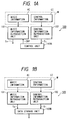
- Fig. 16 is a block diagram of the structure of a conventional device which is referred to as an LVD kara-oke playing device.
- the illustrated LVD kara-oke playing device K1 includes an LVD automatic changer PL1 which houses and reproduces a plurality of laser video disks D1 each serving as a kara-oke information recording medium, a commander CM1 which controls the LVD automatic changer PL1 to select the laser video disks D1 in the LVD automatic changer PL1 in accordance with a request input from an operation part CB1, an amplifier AM1 and speakers SP1, SP2 which are used to output a reproduced audio signal as sounds, an image display device GD1 which displays a reproduced image signal as an image, and a microphone MC1 which is used to convert a sound sung into an audio signal and output the audio signal to the amplifier AM1.
- the amplifier AM1 mixes the audio signal from the LVD automatic changer PL1, which is a so called kara-oke music sound, with the audio signal of the sung sound from the microphone MC1 and then outputs the mixed audio signal to the speakers SP1, SP2.
- the commander CM1 can normally include the operation part CB1.
- the CD kara-oke playing device K2 includes a CD automatic changer PL2 for housing and reproducing a plurality of compact disks D2 which are a kara-oke information recording medium, a commander CM2 for controlling the CD automatic changer PL2 to select the compact disks D2 in the CD automatic changer PL2 in accordance with a request input from an operation part CB2, an amplifier AM2 and speakers SP3, SP4 respectively used to output a reproduced audio signal as a sound, a graphic decoder DE for converting graphic data reproduced from subcode data in the compact disk D2 into an image signal, an image display device GD2 for displaying the image signal as an image, and a microphone MC2 for converting a sung sound into an audio signal and outputting the audio signal to the amplifier AM2.
- a graphic decoder DE for converting graphic data reproduced from subcode data in the compact disk D2 into an image signal
- an image display device GD2 for displaying the image signal as an image
- a microphone MC2
- the amplifier AM2 mixes the audio signal from the CD automatic changer PL2, which is a so called a kara-oke music, with the audio signal of the sung sound from the microphone MC2 and output the mixed audio signal to the speakers SP3, SP4.
- the commander CM2 may normally include the operation part CB2 and graphic decoder DE.
- a recorded information reproducing device 100 for reproducing music form an information recording medium M on which encoded music information AI and control information CI are recorded according to the MIDI standards, the device 100 comprising: music information reproduction means 101 for decoding the encoded music information to output a reproduced music signal S A ; control information reproduction means 102 for decoding the encoded control information CI to output a clock signal S C for timing control; and, control means 103A, in accordance with the clock signal S C , for controlling the sequence of reproduction of the music information in the music information reproduction means 101.
- a recorded information reproducing device 100 for reproducing a sound from an information recording medium M in which encoded music information AI and control information CI are recorded according to the MIDI standards, the recorded information reproducing device 100 including musical information reproduction means 101 for decoding the encoded music information and outputting reproduced music information S A , control information reproduction means 102 for decoding the encoded control information CI and outputting a clock signal S c for control of a timing, and data storage means 103B, in accordance with the clock signal S c , for storing the reproduced music information S A temporarily and then outputting the same.
- the timing controlling clock signal out of the subcode information according to the MIDI standards by using the timing controlling clock signal out of the subcode information according to the MIDI standards, repeated play or the like is possible at the accurate position of the lyrics irrespective of the tempo of music, which facilitates the singing practice to the kara-oke device.
- the timing control clock signal among the subcode information according to the MIDI standards to thereby allow the data storage means 103B to store data provisionally, repetitive playing and the like can be realized at the accurate position of the lyric lines of music irrespective of the tempo of the music, which can facilitate the practice by use of a kara-oke device.
- MIDI Musical Instrument Digital Interface
- a MIDI instrument which includes hardware according to the MIDI standards and has a function to transmit and receive a MIDI control signal, that is, an instrument playing control signal of a type defined to carry music information.
- disks such as a CD (compact disk), a CD-V (video), and LVD (laser video disk) including a CD format digital sound and the like as well as in tapes such as a DAT and the like
- a subcode which consists of P, Q, R, S, T, U, V and W channels.
- P and Q channels are used to control a disk player or for the purpose of display.
- R ⁇ W channels are respectively an empty channel which is referred to as a user's bit.
- the application of the user's bit has been studied in various fields such as a graphic, a sound, an image and the like and standards for a graphic format have already been proposed.
- the user's bit is also capable of recording a MIDI format signal therein and the standards for the user's bit have already been proposed as well.
- an audio video signal reproduced by a disk player can be supplied to an AV system so that a program recorded on the disk can be seen and listened and, at the same time, the disk player can be combined with the AV system or playing program information can be supplied to other MIDI instruments. Therefore, the user's bit has been studied for its application in various fields such as construction of an AV system with a concert-hall presence including an electronic musical instrument, preparation of educational software and the like.
- the MIDI instrument plays music along an instrument playing program to be formed by MIDI signals which can be obtained by converting MIDI format signals supplied sequentially from a disk player into serial signals.
- the MIDI control signal that are supplied to the MIDI instrument are respectively serial data having a transfer rate of 31.25 [K baud], in which 1 byte of data is composed of a total of 10 bits including 8 bits of data, 1 bit of start bit and 1 bit of stop bit.
- a message which provides music information can be made up by combining at least one status byte for specifying the kind of data to be transmitted and a MIDI channel with one or two data bytes to be guided by the status. Therefore, one message is composed of 1 ⁇ 3 bytes and it takes a transfer time of 320 ⁇ 960 [ ⁇ sec] to transfer the message.
- An instrument playing program is formed of a series of messages.
- Fig. 5 a structure of a note-on-message which is one of channel voice messages.
- the note-on-message of the status byte is, for example, an instruction corresponding to an operation to depress a key on a keyboard and is used in a pair with a note-off-message corresponding to an operation to release the key of the keyboard.
- the note number of the data byte 1 specifies one of 128 stages allocated to the keys of a keyboard of an 88-key piano with the [central C] of the piano as a center.
- the velocity of the data byte 2 is in general used to differentiate the stresses of sounds.
- the MIDI instrument when the MIDI instrument is given a note-on-message, then the MIDI instrument generates a sound of a specified scale at a specified stress. Also, when it receives a note-off-message, then the MIDI instrument performs, for example, an operation to release the key of the piano keyboard.
- the system real time message is used to allow the MIDI instrument to be operated in a synchronized manner.
- the system real time message contains therein a timing clock.
- a MIDI connected system is able to operate in a synchronized manner due to this message (F8h, (h:hexa-decimal digit)) which is supplied thereto at a rate of 24 per a quarter note.
- the data transmitting side may continue to transmit the timing clocks (F8h) according to its own tempo information even when no playing is performed.
- the data receiving side which is set in a MIDI sink mode (which is a mode to be synchronized with a timing clock of MIDI IN), can be synchronized with an external clock in a state in which it waits for start (FAh) or continue (FBh).
- a MIDI sink mode which is a mode to be synchronized with a timing clock of MIDI IN
- FAh start
- FBh continue
- a MIDI sound source module MD an amplifier AM and a speaker SP can be used to produce an arbitrary musical sound by means of a MIDI control signal S MIDI .
- Fig. 8 there is shown a data structure of a MIDI kara-oke file stored in an optical disk which is an information recording medium.
- This MIDI kara-oke file format KF is mainly classified into a sequence file SF and a chart file IF.
- the sequence file SF is a file which is necessary while the kara-oke is being played and also which includes a note file NF, a lyrics file LF and a PCM file PF.
- the note file NF is a file in which actual play data is stored and also which includes data areas NF1 ⁇ NF17. Among these areas, a tone color track NF3 is an area for strong data used to set a plurality of tone colors for the MIDI sound source.
- a conductor track NF5 is an area for strong data used to set a rhythm and a tempo. A tempo change and the like are stored in this data area.
- a rhythm pattern track NF7 is an area for storing pattern data in a measure relating to a rhythm. Tracks NF8 ⁇ NF15 are respectively referred to as note tracks, allowing use of up to 16 tracks. Data for playing the MIDI sound source are stored in these tracks.
- a track INF9 is a track exclusively used for storage of melody and a track NF15 is an exclusive track for storage of rhythm.
- Track numbers a ⁇ n are 2 ⁇ 15, respectively.
- control tracks NF16 and NF17 are used to store various kinds of control commands such as illumination control, LVD player control and the like.
- the track header portion NF16 is composed of only track length data.
- the track length data has a status byte NF61 and a data byte NF62.
- the status byte NF61 is an FFh: (h: hexa-decimal digit), while the data byte NF62 includes four bytes, that is, 00h, 00h, 00h and 00h.
- various control commands are stored in control command data NF71.
- the control commands include, for example, an illumination presentation command, a video image presentation, a laser video control command, an effect control command and the like.
- Each of data specifications includes its own byte.
- a data specification for control of the illumination presentation includes a status byte F1h and a data byte.
- a data specification for control of the video image presentation includes a status byte F2h and a data byte.
- a data specification for control of the laser video includes a status byte F4h and a data byte.
- This laser video control command corresponds to image control information.
- the laser video control command is constructed, for example, in such a manner as F3h, AAh, BBh, CCh, ---.
- AAh represents a disk number
- BBh stands for a reproducing surface (such as A surface, B surface or the like)
- CCh points out a chapter number of a screen number.
- track end data NF72 is constructed in such a manner that the status byte is FEh and data byte is FEh.
- the lyrical line file LF is a file to store the data of lyrical line telops to be displayed on a monitor TV and, as shown in Fig. 11, includes data areas LF1 ⁇ LF13. Among them, LF3 and LF7 are used to store the data of the lyrical lines themselves. Also, LF4 and LF8 are used to store data as to when the lyrical lines are displayed and as to at what speed the lyrical lines are changed in color (scrolled).
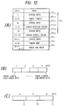
- Fig. 12 shows LF2 ⁇ LF5 by way of example.
- the track header portion LF2 is a data area which stores therein data to specify a track length, an initial value of a lyrics file telop display color, and an initial value of a lyrics file telop scroll color, and the track header portion LF2 includes LF21 ⁇ LF26.
- the data for the lyrics telop display color and lyrics telop scroll color may be omitted. In this case, the data are respectively set to given initial values (default values) by the control part.
- a status byte LF21 for a track length is 1 byte (FFh, h:hexadecimal digit), while track length data LF22 is 4 bytes, as shown in Fig. 12(B). the data of LF22 is stored from 1 byte which is a high order byte (MSB) of the track length.
- MSB high order byte
- a status LF23 for a lyrical display color is 1 byte (A0h)
- a lyrics display color data LF24 is 3 bytes, as shown in Fig. 12(C).
- Display colors for lyrics telops are specified by means of B (blue), R (red) and G (green). The first byte of these data bytes is specified with B (blue), the second byte is specified with R (red), and the third byte is specified with G (green), respectively in a range of 00h ⁇ 0Fh.
- a scroll color status LF25 is 1 byte (B0h) and scroll color data LF26 is 3 bytes.
- the specification of the data bytes is similar to that in the case of the lyrics display color.
- the lyrics data is stored in accordance with a predetermined format, such as a JIS code.
- the status of the lyrics data LF3 is C0h and, in the case of the lyrics data, lyrics data following the status C0h are displayed in a screen. Also, the data strings following the status C0h are respectively allocated lyrics numbers in such a sequential order that 1 is allocated to the first data string.
- the data end status and data are E0h.
- the data of a timing map LF4 includes a lyrics telop display timing, a lyrics telop erase timing, a lyrics display color, a scroll color, scroll map data and a map end.
- the status of the lyrics telop display timing is DFh and the data thereof is 3 bytes which comprise [Display Timing] and (Lyrics Number].
- the lyrics of the [Lyrics Number] is displayed at a timing of the [Display Timing]. Referring to the display timing, the first byte of the data is set in the high-order byte of the timing and the second byte is set in the low-order byte of the timing.
- the status 2 of the lyrics telop erase timing is D0h and the data thereof is [Off Timing] of 2 bytes.
- the first byte of the data is a hi-order byte of the timing, while the second byte is a low-order byte of the timing.
- the status of the lyrics display color is A0h and the data thereof is [Display Color] of 3 bytes.
- the format of the data is the same as the format of the lyrics display color in the track header. However, in the timing map, the format must be present after the lyrics telop display timing.
- the status of the scroll color is B0h and the data thereof is [Scroll Color] of 3 bytes.
- the format of the data is the same as the format of the scroll color in the track header. However, in the timing map, the format must be present before the scroll map data.
- the status of the scroll map data is C0h and the data thereof is 2 bytes which comprise [Scroll Speed] and [Lyrics Count].
- the number of characters of the [Lyrics Count] is scrolled at the speed of the musical note of the [Scroll Speed] per character.
- LF6 ⁇ LF13 are capable of storing the lyrics written in two or more languages, parodies and the like. However, they are not stored when they are not used.
- a PCM filed PF is a file which is used to store data of such effective sounds as cannot be generated by the MIDI sound source, background chorus and the like and, as shown in Fig. 14, the PCM file PF includes data areas PF1 ⁇ PF6.
- the data storage method there can be employed various kinds of methods such as PCM (Pulse Code Modulation), ADPCM (Adaptive Differential Pulse code Modulation) and the like.
- a chart file IF is a retrieval file necessary for request and, as shown in Fig. 15, includes information filed IF1 and IF2.
- the information file IF1 contains therein the names of songs, the names of singers, the names of lyric writers, the names of composers, the genres of songs, lyrics for retrieval, LVD screen setup data and the like.
- the intro sequence track IF2 is used to store therein sequence data which allows the MIDI sound source to play a measure of a song.
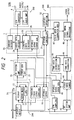
- FIG. 2 there is shown a block diagram of a CDV player which is a first embodiment of a recorded information reproducing device according to the invention.
- the CDV player 100A as shown in Fig. 2, consists mainly of an information read system 200, an audio reproduction system 300, a video reproduction system 400, and a control system 500.
- the information read system 200 includes a spindle motor 11 which is used to rotationally drive a CDV disk DK serving as an information recording medium, a pickup 12 used to read information from the CDV disk DK, a servo mechanism 13 for driving the pickup 12, an APC (Automatic Power Control) circuit 14 and a servo part 1.
- the servo part 1 includes a tracking focus carriage servo circuit 15 for servo controlling the pick up 12 and servo mechanism 13, and a spindle servo circuit 16 for servo controlling the spindle motor 11.
- the audio reproduction system 300 includes a pre-amplifier part 2, a decoder part 3 and a DA converter part 4.
- the pre-amplifier part 2 includes an RF system amplifier 21 and an error generation circuit 22.
- the decoder part 3 includes a subcode decode circuit 23, an audio data code circuit 24, a control data decode circuit 25 and a spindle servo error generation circuit 26.
- the DA converter part 4 comprises a DA converter 27 and an LPF audio amplifier 20.
- the control system 500 includes a system controller part 31 and a display/operation part 32.
- the video reproduction system 400 includes an EFM (Eight to Fourteen Modulation) sampling part 41, a spindle servo error generation circuit 43, a video image demodulation part 44, a time axis correction servo part 45, a time axis correction part 46, a blue back character generator 47 and a video image signal processing part 48.
- EFM Eight to Fourteen Modulation
- the CVD side DK is rotationally driven by the spindle motor 11 and the recorded information is read by the pickup 12 by means of a laser beam B and is then converted into an electric signal.
- the operation of the pickup 12 is driven and controlled by the servo mechanism 13 to be controlled by the servo part 1.
- a semiconductor laser is used as a light source for reading information recorded in a disk.
- the light output of the semiconductor laser may vary with respect to the same current, so that a signal obtained from the disk can vary with respect to the variations of the temperatures.
- the light output may vary due to the change with passage of time as well.
- the APC circuit 14 is a circuit which is used to maintain the light output of the semiconductor laser at a constant level with respect to the time change and temperature variations.
- a disk information signal read by the pickup 12 is transmitted to the RF system amplifier 21 and error generation circuit 22, and is then transmitted to the audio data decode circuit 24 and spindle servo error generation circuit 26.
- An audio signal is decoded by the audio data decode circuit 24 and is then transmitted to the subcode decode circuit 23, control data decode circuit 25 and DA converter 27.
- the DA converter 27 converts the decoded digital signal into an analog signal and then transmits the analog signal to the LPF audio amplifier 28.
- the LPF audio amplifier 28 at first, operates a low pass filter (LPF) to adjust the bands of the analog signal to thereby adjust the output level of the analog signal, and then outputs the analog signal externally as an audio output. If an external amplifier or external speaker (which is not shown in Fig. 2) is connected to the LPF audio amplifier 28, then the audio output can be output as a sound or a voice.
- LPF low pass filter
- the error generation circuit 22 From the signal transmitted to the error generation circuit 22, the error generation circuit 22 generates a tracking error signal, a focus error signal and a carriage error signal, which provide basic signals for servo control, and then transmits these signals to the tracking focus carriage servo circuit 15.
- the tracking focus carriage servo circuit 15 based on these error signals, generates a signal used to drive the pickup 12 or servo mechanism 13 and outputs the drive signal to the pickup 12 or servo mechanism 13.
- the spindle error generation circuit 26 From the signal transmitted from the RF system amplifier 21 to the spindle servo error generation circuit 26, the spindle error generation circuit 26 generates an error signal for controlling the spindle servo circuit and then outputs the error signal to the spindle servo circuit 16.
- the spindle servo circuit 16 In accordance with the error signal, the spindle servo circuit 16 generates a signal for driving the spindle motor 11 and then outputs the drive signal to the spindle motor 11.
- the subcode decode circuit 23 decodes and extracts a subcode signal and then transmits it to the blue back character generator 47.
- the subcode signal includes therein image signals which can be used to superimpose a character, a symbol, a figure and the like on a screen.
- the blue back character generator 47 extracts these character signals and outputs them to the video signal processing part 48.
- the output of the pickup 12 is transmitted to the EFM sampling part 41 and RF system amplifier 42 as well.
- the EFM sampling part 41 EFM demodulates the signal and returns it to the RF system amplifier 21.
- the signal, the level of which is adjusted in the RF system amplifier 42 is transmitted to the video demodulation part 44, in which a video signal is demodulated.
- the video signal is then transmitted to the spindle servo error generation circuit 43 and time axis correction part 46.
- the spindle servo error generation circuit 43 outputs this video signal to the spindle servo circuit 16, thereby allowing the circuit 16 to perform its spindle servo control.
- the video signal transmitted to the time axis correction part 46 is applied time axis servo by the time axis correction servo part 45 and time axis correction part 46, and after then the video signal is output to the video signal processing part 48.
- the video signal processing part 48 there is transmitted from the blue back character generator 47 a character signal for superimposing, and the character signal is superimposed on the video signal before it is output externally as a video output.
- the CDV player 100A can also be operated from externally by the display/operation part 32 and an operation instruction input therein is transmitted to the system controller part 31.
- the system controller part 31 outputs a control signal to the control data decode circuit 25, tracking focus carriage servo circuit 15, spindle servo circuit 16, video image demodulation part 44 and blue back character generator 47, thereby controlling these parts.
- the control data decode circuit 25 decodes the control data from the decode signal transmitted from the audio data decode circuit 24 and then transmits the control data to the system controller part 31.
- the tracking focus carriage servo circuit 15 and spindle servo circuit 16 also transmit the servo information to the system controller part 31.
- a control data decode circuit 25 extracts a timing clock signal (F8h) serving as time information out of decoded audio reproduction signal. 24 such timing clock signals provide a time of a quarter note. Therefore, in the case of a four-four time, 16 quarter notes provide a time of four bars.
- F8h timing clock signal
- 16 quarter notes provide a time of four bars.
- the 4 bars to follow is controlled in such a manner that, during the 4 bars MT5 ⁇ MT8 of the main track, the vocal sound is silent and, during the 4 bars ST5 ⁇ ST8 of the subtrack, the kara-oke accompaniment is played. Due to such control, a person who wants to practice singing a song can listen to the song sung by a professional singer the during the 4 bars ranging from the first measure to the fourth measure and, during the following 4 bars, the person can actually practice singing the song to the kara-oke accompaniment.
- control of the present embodiment can be performed in such a manner that the main track and subtrack can be switched over to each other as well as the channels of the subcode can be switched to thereby switch the kinds of the MIDI instruments so as to change a tone and the like. Also, by driving the pickup 12, it is possible to realize a repeat operation to play the same part of the lyrics repeatedly or a pause operation (a temporary stop operation). Further, the telops of the lyrics can also be displayed to the music reproduction.
- the audio data corresponds to the music information while the control data corresponds to the control information.
- the information read system 200 and the pre-amplification part 2 and audio data decode circuit 24 of the audio reproduction system 300 constitute the music information reproduction means. Also, the information read system 200 and the pre-amplification part 2, audio data decode circuit 24 and control data decode circuit 25 constitute the control information reproduction means. Further, the control system 500 corresponds to the control means.
- the invention is not limited to this, but the invention can also be applied to an LVD player.
- LVD player At present, in general, frequency modulated video image information and music information are recorded on the LVD. In the future, however, it is planned that the vocal part of the LVD is digitized and a subcode signal, a control signal and the like are recorded there.
- OMD Optical Memory Disk
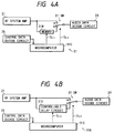
- the system controller part 31 includes a microcomputer part 31C, a memory circuit 31M and a switching switch 31SW. At first, the switching switch 31SW is initially connected to an a side in Fig. 4A.
- timing clock signal (F8h) representing time information
- the memory circuit 31M temporarily stores musical information corresponding to, for example, one phrase (4 bars) out of the musical information that is transmitted from the RF system amplifier 21.
- a control signal S c2 is output from the microcomputer 31C to the switching switch 31SW, with the result that the switch 31SW is connected to a b side in Fig. 4A. Therefore, since the temporarily stored musical information corresponding to 4 bars is input to the audio data decode circuit, the same phrase can be played repeatedly. In this case, if the disk is temporarily stopped or the laser beam is controlled to go back to the same position by means of an instruction from the microcomputer 31C, then play can be resumed at the original position after the repeated playings.
- Fig. 4B there is shown a block diagram of the structure of a system controller part employed in another embodiment of a recorded information reproducing device according to the invention.
- the system controller part 31A includes a controllable delay circuit 31D in place of the memory circuit 31M which is employed in the system controller part 31 in the previously-mentioned embodiment.
- This structure can also obtain a similar effect to the previous embodiment.
- the above-mentioned repeated playing can be realized not only by repeating the same track but also by switching the channels (which are classified by the kinds of musical instruments) of the MIDI.
- reproduction is also possible by switching tracks from one to another in such a manner that a main track, on which vocal music is recorded, is firstly reproduced and after then a temporarily stored subtrack (kara-oke playing) is reproduced.
- a control signal for pause may be transmitted from the system controller part 31A to the audio data decoder part 24 and DA converter part 27, which correspond to MIDI sound source means, and, after one phrase is played, a disk may be temporarily paused while the temporarily stored data is played one phrase. In doing so, the play can be resumed at the original position. Also, a lyrics telop can be displayed to the music reproduction.
- audio data correspond to the musical information
- control data correspond to the control information
- the information read system 200 and the pre-amplification part 2 and audio data decode circuit 24 of the audio reproduction system 300 constitute musical information reproduction means.
- the information read system 200 and the pre-amplification part 2, audio data decode circuit 24 and control data decode circuit 25 constitute control information reproduction means.
- the system controller parts 31, 31A correspond to data storage means, respectively.
- an LVD player may be used instead of the CDV player.
- frequency modulated video image information and vocal information are recorded on the LVD but, in the future, it is also planned that the vocal part is digitalized and a subcode signal or a control signal is recorded therein.
- OMD Optical Memory Disk
- a given part of music can be practiced repeatedly in synchronisation with the progress of the music. Also, after listening to a given part of music with vocal sounds, a person can easily practice singing the given part repeatedly to the kara-oke accompaniment.
Abstract

Description
- The present invention relates to a recorded information reproducing device and, in particular, to a recorded information reproducing device preferable to use in a reproducing device such as a kara-oke device (a device for playing an accompaniment recorded on a recording medium) which reproduces sound information recorded on an information recording medium such as a CD (Compact Disk), an LVD (Laser Video Disk) or the like according to the MIDI (Musical Instrument Digital Interface) standards.
- Conventionally, as a so called kara-oke device, there are known some devices which respectively use the CD, LVD or the like.
- Here, Fig. 16 is a block diagram of the structure of a conventional device which is referred to as an LVD kara-oke playing device. As shown in Fig. 16, the illustrated LVD kara-oke playing device K₁ includes an LVD automatic changer PL₁ which houses and reproduces a plurality of laser video disks D₁ each serving as a kara-oke information recording medium, a commander CM₁ which controls the LVD automatic changer PL₁ to select the laser video disks D₁ in the LVD automatic changer PL₁ in accordance with a request input from an operation part CB₁, an amplifier AM₁ and speakers SP₁, SP₂ which are used to output a reproduced audio signal as sounds, an image display device GD₁ which displays a reproduced image signal as an image, and a microphone MC₁ which is used to convert a sound sung into an audio signal and output the audio signal to the amplifier AM₁. The amplifier AM₁ mixes the audio signal from the LVD automatic changer PL₁, which is a so called kara-oke music sound, with the audio signal of the sung sound from the microphone MC₁ and then outputs the mixed audio signal to the speakers SP₁, SP₂. In some cases, the commander CM₁ can normally include the operation part CB₁.
- Also, in Fig. 17, there is shown a block diagram of the structure of a conventional device which is referred to as a CD kara-oke playing device K₂. As shown in Fig. 17, the CD kara-oke playing device K₂ includes a CD automatic changer PL₂ for housing and reproducing a plurality of compact disks D₂ which are a kara-oke information recording medium, a commander CM₂ for controlling the CD automatic changer PL₂ to select the compact disks D₂ in the CD automatic changer PL₂ in accordance with a request input from an operation part CB₂, an amplifier AM₂ and speakers SP₃, SP₄ respectively used to output a reproduced audio signal as a sound, a graphic decoder DE for converting graphic data reproduced from subcode data in the compact disk D₂ into an image signal, an image display device GD₂ for displaying the image signal as an image, and a microphone MC₂ for converting a sung sound into an audio signal and outputting the audio signal to the amplifier AM₂. The amplifier AM₂ mixes the audio signal from the CD automatic changer PL₂, which is a so called a kara-oke music, with the audio signal of the sung sound from the microphone MC₂ and output the mixed audio signal to the speakers SP₃, SP₄. In some cases, the commander CM₂ may normally include the operation part CB₂ and graphic decoder DE.
- According to the above-mentioned structures of the conventional kara-oke devices, one is able to sing a song to the accompaniment of the kara-oke music and is also able to appreciate the image from a display at the same time.
- However, when a person tries to practice the lyrics of a song repeatedly to the above-mentioned conventional kara-oke playing device, in the case of the LVD kara-oke device, the person can repeat only every chapter of the lyrics and thus the current chapter does not always coincide with the beginning of the lyrics the person wants to sing. Also, in the case of the CD kara-oke device, repetition to an arbitrary desired position of the lyric lines of a song is possible but, for example, such repeated practice is not possible as firstly the person listens to the kara-oke playing and singing of the lyric lines of music the person wants to practice simultaneously for four bars to the tempo of the music and next the person practices the singing of the lyric lines of the same four bars of the music while only the kara-oke playing is being accompanied.
- In view of the above-mentioned circumstances of the conventional kara-oke devices, it is an object of the invention to provide a recorded information reproducing device which can realize a repetitive practice synchronized with the progress of music in a kara-oke device and the like.
- In order to solve the above-mentioned problems, according to the first aspect of the invention, as shown in Fig. 1A which is an explanatory view of the principles of the invention, there is provided a recorded
information reproducing device 100 for reproducing music form an information recording medium M on which encoded music information AI and control information CI are recorded according to the MIDI standards, thedevice 100 comprising: music information reproduction means 101 for decoding the encoded music information to output a reproduced music signal SA; control information reproduction means 102 for decoding the encoded control information CI to output a clock signal SC for timing control; and, control means 103A, in accordance with the clock signal SC, for controlling the sequence of reproduction of the music information in the music information reproduction means 101. - In order to solve the above-mentioned problems, according to the second aspect of the invention, as shown in Fig. 1B which is an explanatory view of the principles of the invention, there is provided a recorded
information reproducing device 100 for reproducing a sound from an information recording medium M in which encoded music information AI and control information CI are recorded according to the MIDI standards, the recordedinformation reproducing device 100 including musical information reproduction means 101 for decoding the encoded music information and outputting reproduced music information SA, control information reproduction means 102 for decoding the encoded control information CI and outputting a clock signal Sc for control of a timing, and data storage means 103B, in accordance with the clock signal Sc, for storing the reproduced music information SA temporarily and then outputting the same. - According to the first aspect of the invention having the above structure, by using the timing controlling clock signal out of the subcode information according to the MIDI standards, repeated play or the like is possible at the accurate position of the lyrics irrespective of the tempo of music, which facilitates the singing practice to the kara-oke device.
- According to the second aspect of the invention having the above-mentioned structure, by using the timing control clock signal among the subcode information according to the MIDI standards to thereby allow the data storage means 103B to store data provisionally, repetitive playing and the like can be realized at the accurate position of the lyric lines of music irrespective of the tempo of the music, which can facilitate the practice by use of a kara-oke device.
- In the accompanying drawings:-
- Figs. 1A and 1B are explanatory views of the principles of the invention;
- Fig. 2 is a block diagram of the structure of a first embodiment of a recorded information reproducing device according to the invention;
- Fig. 3 is a diagram showing an operation of the first embodiment of the present invention;
- Figs. 4A and 4B are block diagrams of the structure of a system controller part employed in a second embodiment according to the invention;
- Fig. 5 is a view of the structure of a note-on-message employed in the MIDI;
- Fig. 6 is a view of a note-on-message and a note-off-message;
- Fig. 7 is a view of the structure of a musical sound generation device according to the MIDI;
- Fig. 8 is a view of the structure of an MIDI kara-oke format used in the invention;
- Fig. 9 is a view of the structure of a note file shown in Fig. 8;
- Fig. 10 is a view of the details of the structure of the note file shown in Fig. 9;
- Fig. 11 is a view of the structure of a lyrics file shown in Fig. 8;
- Fig. 12 is a view of the details of the structure of the lyrics file shown in Fig. 11;
- Fig. 13 is a view of an example of a color code shown in Fig. 12;
- Fig. 14 is a view of the structure of a PCM file shown in Fig. 8;
- Fig. 15 is a view of the structure of a chart file shown in Fig. 8;
- Fig. 16 is a block diagram of the structure of a conventional LVD kara-oke device; and,
- Fig. 17 is a block diagram of the structure of a conventional CD kara-oke device.
- Prior to description of embodiments of a recorded information reproducing device according to the invention, description will be give of the MIDI standards, MIDI sound source and MIDI kara-oke format used in the present invention with reference to Figs. 5 through 15.
- MIDI (Musical Instrument Digital Interface) standards are standards which are established so that musical instruments such as a synthesizer, an electronic piano and the like are interconnected with one another to thereby be able to exchange information therebetween.
- An electronic musical instrument is referred to as a MIDI instrument, which includes hardware according to the MIDI standards and has a function to transmit and receive a MIDI control signal, that is, an instrument playing control signal of a type defined to carry music information.
- In disks such as a CD (compact disk), a CD-V (video), and LVD (laser video disk) including a CD format digital sound and the like as well as in tapes such as a DAT and the like, there is recorded a subcode which consists of P, Q, R, S, T, U, V and W channels. Among the channels, P and Q channels are used to control a disk player or for the purpose of display.
- On the other hand, R ∼ W channels are respectively an empty channel which is referred to as a user's bit. The application of the user's bit has been studied in various fields such as a graphic, a sound, an image and the like and standards for a graphic format have already been proposed.
- The user's bit is also capable of recording a MIDI format signal therein and the standards for the user's bit have already been proposed as well.
- In this case, an audio video signal reproduced by a disk player can be supplied to an AV system so that a program recorded on the disk can be seen and listened and, at the same time, the disk player can be combined with the AV system or playing program information can be supplied to other MIDI instruments. Therefore, the user's bit has been studied for its application in various fields such as construction of an AV system with a concert-hall presence including an electronic musical instrument, preparation of educational software and the like.
- The MIDI instrument plays music along an instrument playing program to be formed by MIDI signals which can be obtained by converting MIDI format signals supplied sequentially from a disk player into serial signals.
- At first, the MIDI control signal that are supplied to the MIDI instrument are respectively serial data having a transfer rate of 31.25 [K baud], in which 1 byte of data is composed of a total of 10 bits including 8 bits of data, 1 bit of start bit and 1 bit of stop bit.
- Also, a message which provides music information can be made up by combining at least one status byte for specifying the kind of data to be transmitted and a MIDI channel with one or two data bytes to be guided by the status. Therefore, one message is composed of 1 ∼ 3 bytes and it takes a transfer time of 320 ∼ 960 [µ sec] to transfer the message. An instrument playing program is formed of a series of messages.
- As an example of such message, there is shown in Fig. 5 a structure of a note-on-message which is one of channel voice messages.
- The note-on-message of the status byte is, for example, an instruction corresponding to an operation to depress a key on a keyboard and is used in a pair with a note-off-message corresponding to an operation to release the key of the keyboard. This is shown in Fig. 6. The note number of the
data byte 1 specifies one of 128 stages allocated to the keys of a keyboard of an 88-key piano with the [central C] of the piano as a center. The velocity of thedata byte 2 is in general used to differentiate the stresses of sounds. when the MIDI instrument is given a note-on-message, then the MIDI instrument generates a sound of a specified scale at a specified stress. Also, when it receives a note-off-message, then the MIDI instrument performs, for example, an operation to release the key of the piano keyboard. - Also, as a further message, there is a system real time message. The system real time message is used to allow the MIDI instrument to be operated in a synchronized manner. The system real time message contains therein a timing clock. A MIDI connected system is able to operate in a synchronized manner due to this message (F8h, (h:hexa-decimal digit)) which is supplied thereto at a rate of 24 per a quarter note. The data transmitting side may continue to transmit the timing clocks (F8h) according to its own tempo information even when no playing is performed. The data receiving side, which is set in a MIDI sink mode (which is a mode to be synchronized with a timing clock of MIDI IN), can be synchronized with an external clock in a state in which it waits for start (FAh) or continue (FBh).
- From the foregoing description, therefore, instead of an electronic musical instrument, as shown in Fig. 7, a MIDI sound source module MD, an amplifier AM and a speaker SP can be used to produce an arbitrary musical sound by means of a MIDI control signal SMIDI.
- Description will be given below of a MIDI kara-oke file format for use in the present invention with reference to Figs. 8 to 15.
- In Fig. 8, there is shown a data structure of a MIDI kara-oke file stored in an optical disk which is an information recording medium.
- This MIDI kara-oke file format KF is mainly classified into a sequence file SF and a chart file IF. The sequence file SF is a file which is necessary while the kara-oke is being played and also which includes a note file NF, a lyrics file LF and a PCM file PF.
- The note file NF is a file in which actual play data is stored and also which includes data areas NF₁ ∼ NF₁₇. Among these areas, a tone color track NF₃ is an area for strong data used to set a plurality of tone colors for the MIDI sound source. A conductor track NF₅ is an area for strong data used to set a rhythm and a tempo. A tempo change and the like are stored in this data area. A rhythm pattern track NF₇ is an area for storing pattern data in a measure relating to a rhythm. Tracks NF₈ ∼ NF₁₅ are respectively referred to as note tracks, allowing use of up to 16 tracks. Data for playing the MIDI sound source are stored in these tracks. In particular, a track INF₉ is a track exclusively used for storage of melody and a track NF₁₅ is an exclusive track for storage of rhythm. Track numbers a ∼ n are 2 ∼ 15, respectively. Also, control tracks NF₁₆ and NF₁₇ are used to store various kinds of control commands such as illumination control, LVD player control and the like.
- Referring now to Fig. 10, there is shown a view of the detailed structures of the header portion of the track NF₁₆ and control command track NF₁₇. The track header portion NF₁₆ is composed of only track length data. The track length data has a status byte NF₆₁ and a data byte NF₆₂. The status byte NF₆₁ is an FFh: (h: hexa-decimal digit), while the data byte NF₆₂ includes four bytes, that is, 00h, 00h, 00h and 00h. Also, various control commands are stored in control command data NF₇₁. The control commands include, for example, an illumination presentation command, a video image presentation, a laser video control command, an effect control command and the like. Each of data specifications includes its own byte. That is, a data specification for control of the illumination presentation includes a status byte F1h and a data byte. A data specification for control of the video image presentation includes a status byte F2h and a data byte. A data specification for control of the laser video includes a status byte F4h and a data byte. This laser video control command corresponds to image control information. The laser video control command is constructed, for example, in such a manner as F3h, AAh, BBh, CCh, ---. Here, AAh represents a disk number, BBh stands for a reproducing surface (such as A surface, B surface or the like), and CCh points out a chapter number of a screen number. Also, track end data NF₇₂ is constructed in such a manner that the status byte is FEh and data byte is FEh.
- The lyrical line file LF is a file to store the data of lyrical line telops to be displayed on a monitor TV and, as shown in Fig. 11, includes data areas LF₁ ∼ LF₁₃. Among them, LF₃ and LF₇ are used to store the data of the lyrical lines themselves. Also, LF₄ and LF₈ are used to store data as to when the lyrical lines are displayed and as to at what speed the lyrical lines are changed in color (scrolled).
- The further detailed structure of the lyrics file LF is shown in Fig. 12(A). Fig. 12 shows LF₂ ∼ LF₅ by way of example.
- The track header portion LF₂ is a data area which stores therein data to specify a track length, an initial value of a lyrics file telop display color, and an initial value of a lyrics file telop scroll color, and the track header portion LF₂ includes LF₂₁ ∼ LF₂₆. However, the data for the lyrics telop display color and lyrics telop scroll color may be omitted. In this case, the data are respectively set to given initial values (default values) by the control part.
- A status byte LF₂₁ for a track length is 1 byte (FFh, h:hexadecimal digit), while track length data LF₂₂ is 4 bytes, as shown in Fig. 12(B). the data of LF₂₂ is stored from 1 byte which is a high order byte (MSB) of the track length.
- A status LF₂₃ for a lyrical display color is 1 byte (A0h), a lyrics display color data LF₂₄ is 3 bytes, as shown in Fig. 12(C). Display colors for lyrics telops are specified by means of B (blue), R (red) and G (green). The first byte of these data bytes is specified with B (blue), the second byte is specified with R (red), and the third byte is specified with G (green), respectively in a range of 00h ∼ 0Fh.
- A scroll color status LF₂₅ is 1 byte (B0h) and scroll color data LF₂₆ is 3 bytes. The specification of the data bytes is similar to that in the case of the lyrics display color.
- Examples of color codes according to B, R, G are shown in Fig. 13. The lyrics data is stored in accordance with a predetermined format, such as a JIS code.
- The status of the lyrics data LF₃ is C0h and, in the case of the lyrics data, lyrics data following the status C0h are displayed in a screen. Also, the data strings following the status C0h are respectively allocated lyrics numbers in such a sequential order that 1 is allocated to the first data string. The data end status and data are E0h.
- The data of a timing map LF₄ includes a lyrics telop display timing, a lyrics telop erase timing, a lyrics display color, a scroll color, scroll map data and a map end.
- The status of the lyrics telop display timing is DFh and the data thereof is 3 bytes which comprise [Display Timing] and (Lyrics Number].
- The lyrics of the [Lyrics Number] is displayed at a timing of the [Display Timing]. Referring to the display timing, the first byte of the data is set in the high-order byte of the timing and the second byte is set in the low-order byte of the timing.
- The
status 2 of the lyrics telop erase timing is D0h and the data thereof is [Off Timing] of 2 bytes. The first byte of the data is a hi-order byte of the timing, while the second byte is a low-order byte of the timing. - The status of the lyrics display color is A0h and the data thereof is [Display Color] of 3 bytes. The format of the data is the same as the format of the lyrics display color in the track header. However, in the timing map, the format must be present after the lyrics telop display timing.
- The status of the scroll color is B0h and the data thereof is [Scroll Color] of 3 bytes. The format of the data is the same as the format of the scroll color in the track header. However, in the timing map, the format must be present before the scroll map data.
- The status of the scroll map data is C0h and the data thereof is 2 bytes which comprise [Scroll Speed] and [Lyrics Count]. The number of characters of the [Lyrics Count] is scrolled at the speed of the musical note of the [Scroll Speed] per character.
- The status of the map end is E0h and the data thereof is E0h. Also, the status of the track end is FEh and the data thereof is FEh. Further, LF₆ ∼ LF₁₃ are capable of storing the lyrics written in two or more languages, parodies and the like. However, they are not stored when they are not used.
- A PCM filed PF is a file which is used to store data of such effective sounds as cannot be generated by the MIDI sound source, background chorus and the like and, as shown in Fig. 14, the PCM file PF includes data areas PF₁ ∼ PF₆. As the data storage method, there can be employed various kinds of methods such as PCM (Pulse Code Modulation), ADPCM (Adaptive Differential Pulse code Modulation) and the like.
- A chart file IF is a retrieval file necessary for request and, as shown in Fig. 15, includes information filed IF₁ and IF₂. The information file IF₁ contains therein the names of songs, the names of singers, the names of lyric writers, the names of composers, the genres of songs, lyrics for retrieval, LVD screen setup data and the like. The intro sequence track IF₂ is used to store therein sequence data which allows the MIDI sound source to play a measure of a song.
- Next, description will be given below of the preferred embodiments of a recorded information reproducing device according to the invention with reference to the accompanying drawings.
- In Fig. 2, there is shown a block diagram of a CDV player which is a first embodiment of a recorded information reproducing device according to the invention. The
CDV player 100A, as shown in Fig. 2, consists mainly of an information readsystem 200, anaudio reproduction system 300, avideo reproduction system 400, and acontrol system 500. The information readsystem 200 includes aspindle motor 11 which is used to rotationally drive a CDV disk DK serving as an information recording medium, apickup 12 used to read information from the CDV disk DK, aservo mechanism 13 for driving thepickup 12, an APC (Automatic Power Control)circuit 14 and aservo part 1. Also, theservo part 1 includes a tracking focuscarriage servo circuit 15 for servo controlling the pick up 12 andservo mechanism 13, and aspindle servo circuit 16 for servo controlling thespindle motor 11. - The
audio reproduction system 300 includes apre-amplifier part 2, adecoder part 3 and aDA converter part 4. Thepre-amplifier part 2 includes anRF system amplifier 21 and anerror generation circuit 22. Thedecoder part 3 includes asubcode decode circuit 23, an audiodata code circuit 24, a control data decodecircuit 25 and a spindle servoerror generation circuit 26. TheDA converter part 4 comprises aDA converter 27 and an LPF audio amplifier 20. Thecontrol system 500 includes asystem controller part 31 and a display/operation part 32. - The
video reproduction system 400 includes an EFM (Eight to Fourteen Modulation) samplingpart 41, a spindle servoerror generation circuit 43, a videoimage demodulation part 44, a time axiscorrection servo part 45, a timeaxis correction part 46, a blueback character generator 47 and a video imagesignal processing part 48. - Next, description will be give below of the operation of the
present CDV player 100A. - At first, the CVD side DK is rotationally driven by the
spindle motor 11 and the recorded information is read by thepickup 12 by means of a laser beam B and is then converted into an electric signal. The operation of thepickup 12 is driven and controlled by theservo mechanism 13 to be controlled by theservo part 1. Also, in general, a semiconductor laser is used as a light source for reading information recorded in a disk. However, in the semiconductor laser, due to the varying temperatures, the light output of the semiconductor laser may vary with respect to the same current, so that a signal obtained from the disk can vary with respect to the variations of the temperatures. Also, the light output may vary due to the change with passage of time as well. TheAPC circuit 14 is a circuit which is used to maintain the light output of the semiconductor laser at a constant level with respect to the time change and temperature variations. - A disk information signal read by the
pickup 12 is transmitted to theRF system amplifier 21 anderror generation circuit 22, and is then transmitted to the audio data decodecircuit 24 and spindle servoerror generation circuit 26. An audio signal is decoded by the audio data decodecircuit 24 and is then transmitted to thesubcode decode circuit 23, control data decodecircuit 25 andDA converter 27. TheDA converter 27 converts the decoded digital signal into an analog signal and then transmits the analog signal to theLPF audio amplifier 28. TheLPF audio amplifier 28, at first, operates a low pass filter (LPF) to adjust the bands of the analog signal to thereby adjust the output level of the analog signal, and then outputs the analog signal externally as an audio output. If an external amplifier or external speaker (which is not shown in Fig. 2) is connected to theLPF audio amplifier 28, then the audio output can be output as a sound or a voice. - On the other hand, from the signal transmitted to the
error generation circuit 22, theerror generation circuit 22 generates a tracking error signal, a focus error signal and a carriage error signal, which provide basic signals for servo control, and then transmits these signals to the tracking focuscarriage servo circuit 15. The tracking focuscarriage servo circuit 15, based on these error signals, generates a signal used to drive thepickup 12 orservo mechanism 13 and outputs the drive signal to thepickup 12 orservo mechanism 13. Also, from the signal transmitted from theRF system amplifier 21 to the spindle servoerror generation circuit 26, the spindleerror generation circuit 26 generates an error signal for controlling the spindle servo circuit and then outputs the error signal to thespindle servo circuit 16. In accordance with the error signal, thespindle servo circuit 16 generates a signal for driving thespindle motor 11 and then outputs the drive signal to thespindle motor 11. - Also, from the signal transmitted from the audio data decode
circuit 24 to thesubcode decode circuit 23, thesubcode decode circuit 23 decodes and extracts a subcode signal and then transmits it to the blueback character generator 47. The subcode signal includes therein image signals which can be used to superimpose a character, a symbol, a figure and the like on a screen. The blueback character generator 47 extracts these character signals and outputs them to the videosignal processing part 48. - On the other hand, the output of the
pickup 12 is transmitted to theEFM sampling part 41 andRF system amplifier 42 as well. TheEFM sampling part 41 EFM demodulates the signal and returns it to theRF system amplifier 21. Also, the signal, the level of which is adjusted in theRF system amplifier 42, is transmitted to thevideo demodulation part 44, in which a video signal is demodulated. The video signal is then transmitted to the spindle servoerror generation circuit 43 and timeaxis correction part 46. The spindle servoerror generation circuit 43 outputs this video signal to thespindle servo circuit 16, thereby allowing thecircuit 16 to perform its spindle servo control. Also, the video signal transmitted to the timeaxis correction part 46 is applied time axis servo by the time axiscorrection servo part 45 and timeaxis correction part 46, and after then the video signal is output to the videosignal processing part 48. To the videosignal processing part 48, there is transmitted from the blue back character generator 47 a character signal for superimposing, and the character signal is superimposed on the video signal before it is output externally as a video output. - On the other hand, the
CDV player 100A can also be operated from externally by the display/operation part 32 and an operation instruction input therein is transmitted to thesystem controller part 31. In accordance with the input instruction, thesystem controller part 31 outputs a control signal to the control data decodecircuit 25, tracking focuscarriage servo circuit 15,spindle servo circuit 16, videoimage demodulation part 44 and blueback character generator 47, thereby controlling these parts. The control data decodecircuit 25, on the contrary, decodes the control data from the decode signal transmitted from the audio data decodecircuit 24 and then transmits the control data to thesystem controller part 31. Also, the tracking focuscarriage servo circuit 15 andspindle servo circuit 16 also transmit the servo information to thesystem controller part 31. - Description will be given below of the operation of the repeated play and the like which is a characteristic of the present invention by use of Figs. 2 and 3. In Fig. 2, a control data decode
circuit 25 extracts a timing clock signal (F8h) serving as time information out of decoded audio reproduction signal. 24 such timing clock signals provide a time of a quarter note. Therefore, in the case of a four-four time, 16 quarter notes provide a time of four bars. By use of this, if 1 phrase is assumed to be 4 bars, as shown in Fig. 3, at first, during the 4 bars MT₁ ∼ MT₄ of a main track MT, the vocal sound of a singer recorded is played. In this case, in a subtrack ST, the kara-oke accompaniment should be silent during the 4 bars ST₁ ∼ ST₄. - And, if the timing clock signals are counted 384 (24 x 16), then the 4 bars to follow is controlled in such a manner that, during the 4 bars MT₅ ∼ MT₈ of the main track, the vocal sound is silent and, during the 4 bars ST₅ ∼ ST₈ of the subtrack, the kara-oke accompaniment is played. Due to such control, a person who wants to practice singing a song can listen to the song sung by a professional singer the during the 4 bars ranging from the first measure to the fourth measure and, during the following 4 bars, the person can actually practice singing the song to the kara-oke accompaniment. In this case, the control of the present embodiment can be performed in such a manner that the main track and subtrack can be switched over to each other as well as the channels of the subcode can be switched to thereby switch the kinds of the MIDI instruments so as to change a tone and the like. Also, by driving the
pickup 12, it is possible to realize a repeat operation to play the same part of the lyrics repeatedly or a pause operation (a temporary stop operation). Further, the telops of the lyrics can also be displayed to the music reproduction. - Here, the audio data corresponds to the music information while the control data corresponds to the control information.
- The information read
system 200 and thepre-amplification part 2 and audio data decodecircuit 24 of theaudio reproduction system 300 constitute the music information reproduction means. Also, the information readsystem 200 and thepre-amplification part 2, audio data decodecircuit 24 and control data decodecircuit 25 constitute the control information reproduction means. Further, thecontrol system 500 corresponds to the control means. - In the above-mentioned embodiment, the description has been given of the CD player. However, the invention is not limited to this, but the invention can also be applied to an LVD player. At present, in general, frequency modulated video image information and music information are recorded on the LVD. In the future, however, it is planned that the vocal part of the LVD is digitized and a subcode signal, a control signal and the like are recorded there. Also, the invention can also be applied to an OMD (Optical Memory Disk).
- Next, description will be given below of the structure of the
system controller part 31 employed in the embodiment of the second aspect of the invention by use of Figs. 4A and 4B. As shown in Fig. 4A, thesystem controller part 31 includes amicrocomputer part 31C, amemory circuit 31M and a switching switch 31SW. At first, the switching switch 31SW is initially connected to an a side in Fig. 4A. And, when a timing clock signal (F8h) representing time information is output to themicrocomputer 31C from the control data decodecircuit 25 which receives the control data in the MIDI signal, then this timing clock signal is counted and, at a given time, for example, at 384 counts (= 24 x 16), a control signal Sc1 is output to thememory circuit 31M. Responsive to the control signal Sc1, thememory circuit 31M temporarily stores musical information corresponding to, for example, one phrase (4 bars) out of the musical information that is transmitted from theRF system amplifier 21. Then, at a certain count value (for example, after 4 bars), a control signal Sc2 is output from themicrocomputer 31C to the switching switch 31SW, with the result that the switch 31SW is connected to a b side in Fig. 4A. Therefore, since the temporarily stored musical information corresponding to 4 bars is input to the audio data decode circuit, the same phrase can be played repeatedly. In this case, if the disk is temporarily stopped or the laser beam is controlled to go back to the same position by means of an instruction from themicrocomputer 31C, then play can be resumed at the original position after the repeated playings. - Next, in Fig. 4B, there is shown a block diagram of the structure of a system controller part employed in another embodiment of a recorded information reproducing device according to the invention. In Fig. 4B, the
system controller part 31A includes acontrollable delay circuit 31D in place of thememory circuit 31M which is employed in thesystem controller part 31 in the previously-mentioned embodiment. This structure can also obtain a similar effect to the previous embodiment. - Here, it should be noted that the above-mentioned repeated playing can be realized not only by repeating the same track but also by switching the channels (which are classified by the kinds of musical instruments) of the MIDI. In other words, reproduction is also possible by switching tracks from one to another in such a manner that a main track, on which vocal music is recorded, is firstly reproduced and after then a temporarily stored subtrack (kara-oke playing) is reproduced.
- Alternatively, a control signal for pause (temporary stop) may be transmitted from the
system controller part 31A to the audio data decoderpart 24 andDA converter part 27, which correspond to MIDI sound source means, and, after one phrase is played, a disk may be temporarily paused while the temporarily stored data is played one phrase. In doing so, the play can be resumed at the original position. Also, a lyrics telop can be displayed to the music reproduction. - Here, audio data correspond to the musical information and control data correspond to the control information.
- The information read
system 200 and thepre-amplification part 2 and audio data decodecircuit 24 of theaudio reproduction system 300 constitute musical information reproduction means. Also, the information readsystem 200 and thepre-amplification part 2, audio data decodecircuit 24 and control data decodecircuit 25 constitute control information reproduction means. Further, thesystem controller parts - In the above illustrated embodiments description has been given of the CDV player. However, this is not limitative, but according to the invention, an LVD player may be used instead of the CDV player. At present, generally, frequency modulated video image information and vocal information are recorded on the LVD but, in the future, it is also planned that the vocal part is digitalized and a subcode signal or a control signal is recorded therein. Also, the invention can also apply to an OMD (Optical Memory Disk).
- As has been described heretofore, according to the invention, in a kara-oke device or the like, when there is used a disk with a vocal sound recorded on the main track thereof and with a kara-oke accompaniment recorded on the subtrack thereof, a given part of music can be practiced repeatedly in synchronisation with the progress of the music. Also, after listening to a given part of music with vocal sounds, a person can easily practice singing the given part repeatedly to the kara-oke accompaniment.
Claims (11)
- A recorded information reproducing device for reproducing a music sound from an information recording medium on which encoded music information and control information are recorded according to the MIDI standards, said recorded information reproducing device comprising:
music information reproduction means for decoding said encoded music information to output a reproduced music signal;
control information reproduction means for decoding said control information to output a clock signal for timing control; and,
control means for controlling a reproduction sequence of said music information of said music information reproduction means in accordance with said clock signal. - A recorded information reproducing device as claimed in claim 1, wherein said a reproduced music signal consists of a first sound signal having an accompaniment with a vocal sound and a second sound signal having the accompaniment only, and said control means switches the reproduction between said first sound signal and said second sound signal.
- A recorded information reproducing device as claimed in claim 1, wherein said control information decoded by said control information reproduction means incudes lyrics data, control data for an external musical instrument, and retrieval data having names of songs, names of singers, names of lyric writers, names of composers, genres of songs.
- A recorded information reproducing device for reproducing a sound from an information recording medium in which encoded music information and encoded control information are recorded according to the MIDI standards, said recorded information reproducing device comprising;
music information reproduction means for decoding said encoded music information to output reproduced music signal;
control information reproduction means for decoding said control information to output a clock signal for timing control; and,
data storage means, in accordance with said clock signal, for storing said reproduced music information temporarily and then outputting the same. - A recorded information reproducing device as claimed in claim 4, wherein said control information decoded by said control information reproduction means incudes lyrics data, control data for an external musical instrument, and retrieval data having names of songs, names of singers, names of lyric writers, names of composers, genres of songs.
- A recorded information reproducing device for reproducing a sound from an information recording medium in which encoded music information and encoded control information are recorded according to the MIDI standards, said recorded information reproducing device comprising;
music information reproduction means for decoding said encoded music information to output reproduced music signal;
control information reproduction means for decoding said control information to output a clock signal for timing control; and,
controllable delay means for delaying said reproduced music information in accordance with said clock signal. - A recorded information reproducing device as claimed in claim 6, wherein said control information decoded by said control information reproduction means incudes lyrics data, control data for an external musical instrument, and retrieval data having names of songs, names of singers, names of lyric writers, names of composers, genres of songs.
- A recorded information reproducing device for reproducing a sound from an information recording medium in which encoded music information and encoded control information are recorded according to the MIDI standards, said recorded information reproducing device comprising;
music information reproduction means for decoding said encoded music information to output reproduced music signal;
control information reproduction means for decoding said control information to output a clock signal for timing control; and,
controllable storage means for storing said reproduced music information in accordance with said clock signal. - A recorded information reproducing device as claimed in claim 8, wherein said control information decoded by said control information reproduction means incudes lyrics data, control data for an external musical instrument, and retrieval data having names of songs, names of singers, names of lyric writers, names of composers, genres of songs.
- A recorded information reproducing device as claimed in claim 8, wherein said storage means comprises a memory for storing a few data of said reproduced music information so that said data can be repeatedly reproduced.
- A recorded information reproducing device as claimed in claim 8, wherein said storage means comprises a memory for storing a predetermined number of bars of said reproduced music information so that said bars can be repeatedly reproduced.
Applications Claiming Priority (4)
| Application Number | Priority Date | Filing Date | Title |
|---|---|---|---|
| JP3204330A JPH0546072A (en) | 1991-08-14 | 1991-08-14 | Recorded information reproducing device |
| JP204329/91 | 1991-08-14 | ||
| JP204330/91 | 1991-08-14 | ||
| JP3204329A JPH0546071A (en) | 1991-08-14 | 1991-08-14 | Recorded information reproducing device |
Publications (2)
| Publication Number | Publication Date |
|---|---|
| EP0529834A1 true EP0529834A1 (en) | 1993-03-03 |
| EP0529834B1 EP0529834B1 (en) | 1998-05-27 |
Family
ID=26514413
Family Applications (1)
| Application Number | Title | Priority Date | Filing Date |
|---|---|---|---|
| EP92307128A Expired - Lifetime EP0529834B1 (en) | 1991-08-14 | 1992-08-04 | Recorded information reproducing device |
Country Status (3)
| Country | Link |
|---|---|
| US (1) | US5805545A (en) |
| EP (1) | EP0529834B1 (en) |
| DE (1) | DE69225653T2 (en) |
Cited By (37)
| Publication number | Priority date | Publication date | Assignee | Title |
|---|---|---|---|---|
| EP0677848A1 (en) * | 1993-10-29 | 1995-10-18 | Kabushiki Kaisha Toshiba | Recording medium and reproducing device for special reproduction |
| EP0677961A2 (en) * | 1994-04-13 | 1995-10-18 | Kabushiki Kaisha Toshiba | Method for recording and reproducing data |
| WO1997010681A1 (en) * | 1995-09-15 | 1997-03-20 | Thomson Consumer Electronics, Inc. | On-screen display timing |
| EP0927977A2 (en) * | 1994-10-12 | 1999-07-07 | Touchtunes Music Corporation | Home digital audiovisual information recording and playback apparatus |
| EP0944034A1 (en) * | 1998-03-20 | 1999-09-22 | Pioneer Electronic Corporation | Apparatus for and method of reproducing music together with information representing beat of music |
| US6034738A (en) * | 1996-02-14 | 2000-03-07 | Thomson Consumer Electronics, Inc. | On-screen display timing |
| US6064794A (en) * | 1995-03-30 | 2000-05-16 | Thomson Licensing S.A. | Trick-play control for pre-encoded video |
| US6363213B1 (en) | 1996-02-14 | 2002-03-26 | Thomson Licensing S.A. | Interface for digital recorder and display |
| EP1261216A1 (en) * | 1995-09-15 | 2002-11-27 | Thomson Multimedia Inc. | Simplified input selector |
| US7321717B1 (en) | 1996-02-14 | 2008-01-22 | Thomson Licensing S.A. | Upgradable on-screen display system |
| CN1917615B (en) * | 1995-09-15 | 2012-06-13 | 汤姆森消费电子有限公司 | Screen display insert |
| EP0926643B1 (en) * | 1994-10-12 | 2013-12-11 | Touchtunes Music Corporation | Intelligent digital audiovisual playback system |
| US9608583B2 (en) | 2000-02-16 | 2017-03-28 | Touchtunes Music Corporation | Process for adjusting the sound volume of a digital sound recording |
| US9646339B2 (en) | 2002-09-16 | 2017-05-09 | Touchtunes Music Corporation | Digital downloading jukebox system with central and local music servers |
| US9769566B2 (en) | 1998-07-22 | 2017-09-19 | Touchtunes Music Corporation | Sound control circuit for a digital audiovisual reproduction system |
| US9774906B2 (en) | 2009-03-18 | 2017-09-26 | Touchtunes Music Corporation | Entertainment server and associated social networking services |
| US9922547B2 (en) | 1998-07-22 | 2018-03-20 | Touchtunes Music Corporation | Remote control unit for activating and deactivating means for payment and for displaying payment status |
| US9921717B2 (en) | 2013-11-07 | 2018-03-20 | Touchtunes Music Corporation | Techniques for generating electronic menu graphical user interface layouts for use in connection with electronic devices |
| US9953341B2 (en) | 2008-01-10 | 2018-04-24 | Touchtunes Music Corporation | Systems and/or methods for distributing advertisements from a central advertisement network to a peripheral device via a local advertisement server |
| US9953481B2 (en) | 2007-03-26 | 2018-04-24 | Touchtunes Music Corporation | Jukebox with associated video server |
| US9959012B2 (en) | 2009-03-18 | 2018-05-01 | Touchtunes Music Corporation | Digital jukebox device with improved karaoke-related user interfaces, and associated methods |
| US9990615B2 (en) | 2007-09-24 | 2018-06-05 | Touchtunes Music Corporation | Digital jukebox device with karaoke and/or photo booth features, and associated methods |
| US10007687B2 (en) | 2000-05-10 | 2018-06-26 | Touchtunes Music Corporation | Device and process for remote management of a network of audiovisual information reproductions systems |
| US10068279B2 (en) | 2000-02-23 | 2018-09-04 | Touchtunes Music Corporation | Process for ordering a selection in advance, digital system and jukebox for embodiment of the process |
| US10104410B2 (en) | 1998-07-22 | 2018-10-16 | Touchtunes Music Corporation | Audiovisual reproduction system |
| US10127759B2 (en) | 1996-09-25 | 2018-11-13 | Touchtunes Music Corporation | Process for selecting a recording on a digital audiovisual reproduction system, and system for implementing the process |
| US10169773B2 (en) | 2008-07-09 | 2019-01-01 | Touchtunes Music Corporation | Digital downloading jukebox with revenue-enhancing features |
| US10228897B2 (en) | 2007-09-24 | 2019-03-12 | Touchtunes Music Corporation | Digital jukebox device with improved user interfaces, and associated methods |
| US10249139B2 (en) | 2007-01-17 | 2019-04-02 | Touchtunes Music Corporation | Coin operated entertainment system |
| US10290006B2 (en) | 2008-08-15 | 2019-05-14 | Touchtunes Music Corporation | Digital signage and gaming services to comply with federal and state alcohol and beverage laws and regulations |
| US10318027B2 (en) | 2009-03-18 | 2019-06-11 | Touchtunes Music Corporation | Digital jukebox device with improved user interfaces, and associated methods |
| US10372301B2 (en) | 2002-09-16 | 2019-08-06 | Touch Tunes Music Corporation | Jukebox with customizable avatar |
| US10373420B2 (en) | 2002-09-16 | 2019-08-06 | Touchtunes Music Corporation | Digital downloading jukebox with enhanced communication features |
| US10564804B2 (en) | 2009-03-18 | 2020-02-18 | Touchtunes Music Corporation | Digital jukebox device with improved user interfaces, and associated methods |
| US10656739B2 (en) | 2014-03-25 | 2020-05-19 | Touchtunes Music Corporation | Digital jukebox device with improved user interfaces, and associated methods |
| US11029823B2 (en) | 2002-09-16 | 2021-06-08 | Touchtunes Music Corporation | Jukebox with customizable avatar |
| US11151224B2 (en) | 2012-01-09 | 2021-10-19 | Touchtunes Music Corporation | Systems and/or methods for monitoring audio inputs to jukebox devices |
Families Citing this family (23)
| Publication number | Priority date | Publication date | Assignee | Title |
|---|---|---|---|---|
| US7188352B2 (en) | 1995-07-11 | 2007-03-06 | Touchtunes Music Corporation | Intelligent digital audiovisual playback system |
| US7424731B1 (en) | 1994-10-12 | 2008-09-09 | Touchtunes Music Corporation | Home digital audiovisual information recording and playback system |
| US8661477B2 (en) | 1994-10-12 | 2014-02-25 | Touchtunes Music Corporation | System for distributing and selecting audio and video information and method implemented by said system |
| FR2769165B1 (en) | 1997-09-26 | 2002-11-29 | Technical Maintenance Corp | WIRELESS SYSTEM WITH DIGITAL TRANSMISSION FOR SPEAKERS |
| FR2781582B1 (en) | 1998-07-21 | 2001-01-12 | Technical Maintenance Corp | SYSTEM FOR DOWNLOADING OBJECTS OR FILES FOR SOFTWARE UPDATE |
| US8726330B2 (en) | 1999-02-22 | 2014-05-13 | Touchtunes Music Corporation | Intelligent digital audiovisual playback system |
| FR2796482B1 (en) | 1999-07-16 | 2002-09-06 | Touchtunes Music Corp | REMOTE MANAGEMENT SYSTEM FOR AT LEAST ONE AUDIOVISUAL INFORMATION REPRODUCING DEVICE |
| JP2001093226A (en) * | 1999-09-21 | 2001-04-06 | Sony Corp | Information communication system and method, and information communication device and method |
| JP2001203977A (en) * | 2000-01-19 | 2001-07-27 | Pioneer Electronic Corp | Information reproducing device |
| FR2805060B1 (en) | 2000-02-16 | 2005-04-08 | Touchtunes Music Corp | METHOD FOR RECEIVING FILES DURING DOWNLOAD |
| FR2811175B1 (en) | 2000-06-29 | 2002-12-27 | Touchtunes Music Corp | AUDIOVISUAL INFORMATION DISTRIBUTION METHOD AND AUDIOVISUAL INFORMATION DISTRIBUTION SYSTEM |
| FR2811114B1 (en) | 2000-06-29 | 2002-12-27 | Touchtunes Music Corp | DEVICE AND METHOD FOR COMMUNICATION BETWEEN A SYSTEM FOR REPRODUCING AUDIOVISUAL INFORMATION AND AN ELECTRONIC ENTERTAINMENT MACHINE |
| FR2814085B1 (en) | 2000-09-15 | 2005-02-11 | Touchtunes Music Corp | ENTERTAINMENT METHOD BASED ON MULTIPLE CHOICE COMPETITION GAMES |
| US6924425B2 (en) * | 2001-04-09 | 2005-08-02 | Namco Holding Corporation | Method and apparatus for storing a multipart audio performance with interactive playback |
| US7087830B2 (en) * | 2001-08-07 | 2006-08-08 | Justin A. Kent | System for converting turntable motion to MIDI data |
| US8103589B2 (en) | 2002-09-16 | 2012-01-24 | Touchtunes Music Corporation | Digital downloading jukebox system with central and local music servers |
| US8584175B2 (en) | 2002-09-16 | 2013-11-12 | Touchtunes Music Corporation | Digital downloading jukebox system with user-tailored music management, communications, and other tools |
| US8151304B2 (en) | 2002-09-16 | 2012-04-03 | Touchtunes Music Corporation | Digital downloading jukebox system with user-tailored music management, communications, and other tools |
| US8332895B2 (en) | 2002-09-16 | 2012-12-11 | Touchtunes Music Corporation | Digital downloading jukebox system with user-tailored music management, communications, and other tools |
| JP3864881B2 (en) * | 2002-09-24 | 2007-01-10 | ヤマハ株式会社 | Electronic music system and program for electronic music system |
| WO2005022539A1 (en) * | 2003-09-01 | 2005-03-10 | The Dream Studio Co., Ltd. | A system for processing music data and a method thereof |
| JP4531546B2 (en) * | 2003-12-15 | 2010-08-25 | パナソニック株式会社 | Indexing system using control signals |
| US9330529B2 (en) | 2007-01-17 | 2016-05-03 | Touchtunes Music Corporation | Game terminal configured for interaction with jukebox device systems including same, and/or associated methods |
Citations (4)
| Publication number | Priority date | Publication date | Assignee | Title |
|---|---|---|---|---|
| US4688105A (en) * | 1985-05-10 | 1987-08-18 | Bloch Arthur R | Video recording system |
| EP0380746A2 (en) * | 1989-01-31 | 1990-08-08 | Pioneer Electronic Corporation | Recording medium playing apparatus |
| EP0384073A2 (en) * | 1989-02-20 | 1990-08-29 | Pioneer Electronic Corporation | Disc playing apparatus |
| US4995026A (en) * | 1987-02-10 | 1991-02-19 | Sony Corporation | Apparatus and method for encoding audio and lighting control data on the same optical disc |
Family Cites Families (7)
| Publication number | Priority date | Publication date | Assignee | Title |
|---|---|---|---|---|
| JPS6171472A (en) * | 1984-09-14 | 1986-04-12 | Pioneer Electronic Corp | Recording disc information reproducing device |
| JP2629173B2 (en) * | 1986-05-15 | 1997-07-09 | ヤマハ株式会社 | Disk playback device |
| JP2565238B2 (en) * | 1987-10-15 | 1996-12-18 | ソニー株式会社 | Optical disc player |
| JPH01256071A (en) * | 1988-04-04 | 1989-10-12 | Pioneer Electron Corp | Recording medium and recording and reproducing device |
| US4992886A (en) * | 1988-12-20 | 1991-02-12 | Wnm Ventures, Inc. | Method and apparatus for encoding data within the subcode channel of a compact disc or laser disc |
| JP2708531B2 (en) * | 1989-03-07 | 1998-02-04 | パイオニア株式会社 | Disc player |
| JPH0449588A (en) * | 1990-06-18 | 1992-02-18 | Pioneer Electron Corp | Information recording medium playing device |
-
1992
- 1992-07-31 US US07/922,501 patent/US5805545A/en not_active Expired - Fee Related
- 1992-08-04 EP EP92307128A patent/EP0529834B1/en not_active Expired - Lifetime
- 1992-08-04 DE DE69225653T patent/DE69225653T2/en not_active Expired - Fee Related
Patent Citations (5)
| Publication number | Priority date | Publication date | Assignee | Title |
|---|---|---|---|---|
| US4688105A (en) * | 1985-05-10 | 1987-08-18 | Bloch Arthur R | Video recording system |
| US4688105B1 (en) * | 1985-05-10 | 1992-07-14 | Short Takes Inc | |
| US4995026A (en) * | 1987-02-10 | 1991-02-19 | Sony Corporation | Apparatus and method for encoding audio and lighting control data on the same optical disc |
| EP0380746A2 (en) * | 1989-01-31 | 1990-08-08 | Pioneer Electronic Corporation | Recording medium playing apparatus |
| EP0384073A2 (en) * | 1989-02-20 | 1990-08-29 | Pioneer Electronic Corporation | Disc playing apparatus |
Cited By (103)
| Publication number | Priority date | Publication date | Assignee | Title |
|---|---|---|---|---|
| EP0677848A4 (en) * | 1993-10-29 | 1996-07-10 | Toshiba Kk | Recording medium and reproducing device for special reproduction. |
| EP0677848A1 (en) * | 1993-10-29 | 1995-10-18 | Kabushiki Kaisha Toshiba | Recording medium and reproducing device for special reproduction |
| US5737308A (en) * | 1993-10-29 | 1998-04-07 | Kabushiki Kaisha Toshiba | Recording medium for specified reproduction and reproduction apparatus |
| EP0677961A3 (en) * | 1994-04-13 | 1997-04-23 | Toshiba Kk | Method for recording and reproducing data. |
| EP0677961A2 (en) * | 1994-04-13 | 1995-10-18 | Kabushiki Kaisha Toshiba | Method for recording and reproducing data |
| EP0926643B1 (en) * | 1994-10-12 | 2013-12-11 | Touchtunes Music Corporation | Intelligent digital audiovisual playback system |
| EP0927977A2 (en) * | 1994-10-12 | 1999-07-07 | Touchtunes Music Corporation | Home digital audiovisual information recording and playback apparatus |
| EP0927977B1 (en) * | 1994-10-12 | 2013-03-06 | Touchtunes Music Corporation | Home digital audiovisual information recording and playback apparatus |
| US6064794A (en) * | 1995-03-30 | 2000-05-16 | Thomson Licensing S.A. | Trick-play control for pre-encoded video |
| US7239793B2 (en) | 1995-09-15 | 2007-07-03 | Thomson Licensing | On-screen display insertion |
| CN1917615B (en) * | 1995-09-15 | 2012-06-13 | 汤姆森消费电子有限公司 | Screen display insert |
| WO1997010681A1 (en) * | 1995-09-15 | 1997-03-20 | Thomson Consumer Electronics, Inc. | On-screen display timing |
| WO1997010682A1 (en) * | 1995-09-15 | 1997-03-20 | Thomson Consumer Electronics, Inc. | Upgradable on-screen display system |
| WO1997010680A1 (en) * | 1995-09-15 | 1997-03-20 | Thomson Consumer Electronics, Inc. | On-screen display insertion |
| EP1261216A1 (en) * | 1995-09-15 | 2002-11-27 | Thomson Multimedia Inc. | Simplified input selector |
| CN1096180C (en) * | 1995-09-15 | 2002-12-11 | 汤姆森消费电子有限公司 | Digital video and interface of display |
| CN1107407C (en) * | 1995-09-15 | 2003-04-30 | 汤姆森消费电子有限公司 | Displaying timer for screen |
| CN1113529C (en) * | 1995-09-15 | 2003-07-02 | 汤姆森消费电子有限公司 | Enhanced display system on screen |
| WO1997010679A1 (en) * | 1995-09-15 | 1997-03-20 | Thomson Consumer Electronics, Inc. | Interface for digital recorder and display |
| US8364014B2 (en) | 1995-09-15 | 2013-01-29 | Thomson Licensing | Upgradable on screen display system |
| CN101005577B (en) * | 1995-09-15 | 2012-10-10 | 汤姆森消费电子有限公司 | Receiver device |
| US7321717B1 (en) | 1996-02-14 | 2008-01-22 | Thomson Licensing S.A. | Upgradable on-screen display system |
| US6363213B1 (en) | 1996-02-14 | 2002-03-26 | Thomson Licensing S.A. | Interface for digital recorder and display |
| US6034738A (en) * | 1996-02-14 | 2000-03-07 | Thomson Consumer Electronics, Inc. | On-screen display timing |
| US10127759B2 (en) | 1996-09-25 | 2018-11-13 | Touchtunes Music Corporation | Process for selecting a recording on a digital audiovisual reproduction system, and system for implementing the process |
| EP0944034A1 (en) * | 1998-03-20 | 1999-09-22 | Pioneer Electronic Corporation | Apparatus for and method of reproducing music together with information representing beat of music |
| US9769566B2 (en) | 1998-07-22 | 2017-09-19 | Touchtunes Music Corporation | Sound control circuit for a digital audiovisual reproduction system |
| US9922547B2 (en) | 1998-07-22 | 2018-03-20 | Touchtunes Music Corporation | Remote control unit for activating and deactivating means for payment and for displaying payment status |
| US10104410B2 (en) | 1998-07-22 | 2018-10-16 | Touchtunes Music Corporation | Audiovisual reproduction system |
| US10846770B2 (en) | 2000-02-03 | 2020-11-24 | Touchtunes Music Corporation | Process for ordering a selection in advance, digital system and jukebox for embodiment of the process |
| US9608583B2 (en) | 2000-02-16 | 2017-03-28 | Touchtunes Music Corporation | Process for adjusting the sound volume of a digital sound recording |
| US10068279B2 (en) | 2000-02-23 | 2018-09-04 | Touchtunes Music Corporation | Process for ordering a selection in advance, digital system and jukebox for embodiment of the process |
| US10007687B2 (en) | 2000-05-10 | 2018-06-26 | Touchtunes Music Corporation | Device and process for remote management of a network of audiovisual information reproductions systems |
| US10452237B2 (en) | 2002-09-16 | 2019-10-22 | Touchtunes Music Corporation | Jukebox with customizable avatar |
| US11314390B2 (en) | 2002-09-16 | 2022-04-26 | Touchtunes Music Corporation | Jukebox with customizable avatar |
| US11663569B2 (en) | 2002-09-16 | 2023-05-30 | Touchtunes Music Company, Llc | Digital downloading jukebox system with central and local music server |
| US10783738B2 (en) | 2002-09-16 | 2020-09-22 | Touchtunes Music Corporation | Digital downloading jukebox with enhanced communication features |
| US9646339B2 (en) | 2002-09-16 | 2017-05-09 | Touchtunes Music Corporation | Digital downloading jukebox system with central and local music servers |
| US10373420B2 (en) | 2002-09-16 | 2019-08-06 | Touchtunes Music Corporation | Digital downloading jukebox with enhanced communication features |
| US10372301B2 (en) | 2002-09-16 | 2019-08-06 | Touch Tunes Music Corporation | Jukebox with customizable avatar |
| US11049083B2 (en) | 2002-09-16 | 2021-06-29 | Touchtunes Music Corporation | Digital downloading jukebox system with central and local music servers and payment-triggered game devices update capability |
| US11029823B2 (en) | 2002-09-16 | 2021-06-08 | Touchtunes Music Corporation | Jukebox with customizable avatar |
| US11756380B2 (en) | 2007-01-17 | 2023-09-12 | Touchtunes Music Company, Llc | Coin operated entertainment system |
| US10970963B2 (en) | 2007-01-17 | 2021-04-06 | Touchtunes Music Corporation | Coin operated entertainment system |
| US10249139B2 (en) | 2007-01-17 | 2019-04-02 | Touchtunes Music Corporation | Coin operated entertainment system |
| US9953481B2 (en) | 2007-03-26 | 2018-04-24 | Touchtunes Music Corporation | Jukebox with associated video server |
| US10228897B2 (en) | 2007-09-24 | 2019-03-12 | Touchtunes Music Corporation | Digital jukebox device with improved user interfaces, and associated methods |
| US10613819B2 (en) | 2007-09-24 | 2020-04-07 | Touchtunes Music Corporation | Digital jukebox device with improved user interfaces, and associated methods |
| US10057613B2 (en) | 2007-09-24 | 2018-08-21 | Touchtunes Music Corporation | Digital jukebox device with karaoke and/or photo booth features, and associated methods |
| US10032149B2 (en) | 2007-09-24 | 2018-07-24 | Touchtunes Music Corporation | Digital jukebox device with karaoke and/or photo booth features, and associated methods |
| US9990615B2 (en) | 2007-09-24 | 2018-06-05 | Touchtunes Music Corporation | Digital jukebox device with karaoke and/or photo booth features, and associated methods |
| US11501333B2 (en) | 2008-01-10 | 2022-11-15 | Touchtunes Music Corporation | Systems and/or methods for distributing advertisements from a central advertisement network to a peripheral device via a local advertisement server |
| US9953341B2 (en) | 2008-01-10 | 2018-04-24 | Touchtunes Music Corporation | Systems and/or methods for distributing advertisements from a central advertisement network to a peripheral device via a local advertisement server |
| US10169773B2 (en) | 2008-07-09 | 2019-01-01 | Touchtunes Music Corporation | Digital downloading jukebox with revenue-enhancing features |
| US11144946B2 (en) | 2008-07-09 | 2021-10-12 | Touchtunes Music Corporation | Digital downloading jukebox with revenue-enhancing features |
| US10290006B2 (en) | 2008-08-15 | 2019-05-14 | Touchtunes Music Corporation | Digital signage and gaming services to comply with federal and state alcohol and beverage laws and regulations |
| US11645662B2 (en) | 2008-08-15 | 2023-05-09 | Touchtunes Music Company, Llc | Digital signage and gaming services to comply with federal and state alcohol and beverage laws and regulations |
| US11074593B2 (en) | 2008-08-15 | 2021-07-27 | Touchtunes Music Corporation | Digital signage and gaming services to comply with federal and state alcohol and beverage laws and regulations |
| US11537270B2 (en) | 2009-03-18 | 2022-12-27 | Touchtunes Music Company, Llc | Digital jukebox device with improved karaoke-related user interfaces, and associated methods |
| US10579329B2 (en) | 2009-03-18 | 2020-03-03 | Touchtunes Music Corporation | Entertainment server and associated social networking services |
| US11520559B2 (en) | 2009-03-18 | 2022-12-06 | Touchtunes Music Company, Llc | Entertainment server and associated social networking services |
| US10782853B2 (en) | 2009-03-18 | 2020-09-22 | Touchtunes Music Corporation | Digital jukebox device with improved karaoke-related user interfaces, and associated methods |
| US9959012B2 (en) | 2009-03-18 | 2018-05-01 | Touchtunes Music Corporation | Digital jukebox device with improved karaoke-related user interfaces, and associated methods |
| US10789285B2 (en) | 2009-03-18 | 2020-09-29 | Touchtones Music Corporation | Digital jukebox device with improved user interfaces, and associated methods |
| US10564804B2 (en) | 2009-03-18 | 2020-02-18 | Touchtunes Music Corporation | Digital jukebox device with improved user interfaces, and associated methods |
| US9774906B2 (en) | 2009-03-18 | 2017-09-26 | Touchtunes Music Corporation | Entertainment server and associated social networking services |
| US11775146B2 (en) | 2009-03-18 | 2023-10-03 | Touchtunes Music Company, Llc | Digital jukebox device with improved karaoke-related user interfaces, and associated methods |
| US11093211B2 (en) | 2009-03-18 | 2021-08-17 | Touchtunes Music Corporation | Entertainment server and associated social networking services |
| US10719149B2 (en) | 2009-03-18 | 2020-07-21 | Touchtunes Music Corporation | Digital jukebox device with improved user interfaces, and associated methods |
| US10228900B2 (en) | 2009-03-18 | 2019-03-12 | Touchtunes Music Corporation | Entertainment server and associated social networking services |
| US10318027B2 (en) | 2009-03-18 | 2019-06-11 | Touchtunes Music Corporation | Digital jukebox device with improved user interfaces, and associated methods |
| US10423250B2 (en) | 2009-03-18 | 2019-09-24 | Touchtunes Music Corporation | Digital jukebox device with improved user interfaces, and associated methods |
| US10963132B2 (en) | 2009-03-18 | 2021-03-30 | Touchtunes Music Corporation | Digital jukebox device with improved karaoke-related user interfaces, and associated methods |
| US11252797B2 (en) | 2010-01-26 | 2022-02-15 | Touchtunes Music Corporation | Digital jukebox device with improved user interfaces, and associated methods |
| US11291091B2 (en) | 2010-01-26 | 2022-03-29 | Touchtunes Music Corporation | Digital jukebox device with improved user interfaces, and associated methods |
| US10901686B2 (en) | 2010-01-26 | 2021-01-26 | Touchtunes Music Corporation | Digital jukebox device with improved user interfaces, and associated methods |
| US11576239B2 (en) | 2010-01-26 | 2023-02-07 | Touchtunes Music Company, Llc | Digital jukebox device with improved user interfaces, and associated methods |
| US11864285B2 (en) | 2010-01-26 | 2024-01-02 | Touchtunes Music Company, Llc | Digital jukebox device with improved user interfaces, and associated methods |
| US10503463B2 (en) | 2010-01-26 | 2019-12-10 | TouchTune Music Corporation | Digital jukebox device with improved user interfaces, and associated methods |
| US10768891B2 (en) | 2010-01-26 | 2020-09-08 | Touchtunes Music Corporation | Digital jukebox device with improved user interfaces, and associated methods |
| US11259376B2 (en) | 2010-01-26 | 2022-02-22 | Touchtunes Music Corporation | Digital jukebox device with improved user interfaces, and associated methods |
| US11700680B2 (en) | 2010-01-26 | 2023-07-11 | Touchtunes Music Company, Llc | Digital jukebox device with improved user interfaces, and associated methods |
| US11395023B2 (en) | 2011-09-18 | 2022-07-19 | Touchtunes Music Corporation | Digital jukebox device with karaoke and/or photo booth features, and associated methods |
| US10848807B2 (en) | 2011-09-18 | 2020-11-24 | Touchtunes Music Corporation | Digital jukebox device with karaoke and/or photo booth features, and associated methods |
| US11368733B2 (en) | 2011-09-18 | 2022-06-21 | Touchtunes Music Corporation | Digital jukebox device with karaoke and/or photo booth features, and associated methods |
| US10225593B2 (en) | 2011-09-18 | 2019-03-05 | Touchtunes Music Corporation | Digital jukebox device with karaoke and/or photo booth features, and associated methods |
| US10582240B2 (en) | 2011-09-18 | 2020-03-03 | Touchtunes Music Corporation | Digital jukebox device with karaoke and/or photo booth features, and associated methods |
| US10582239B2 (en) | 2011-09-18 | 2020-03-03 | TouchTune Music Corporation | Digital jukebox device with karaoke and/or photo booth features, and associated methods |
| US10880591B2 (en) | 2011-09-18 | 2020-12-29 | Touchtunes Music Corporation | Digital jukebox device with karaoke and/or photo booth features, and associated methods |
| US11151224B2 (en) | 2012-01-09 | 2021-10-19 | Touchtunes Music Corporation | Systems and/or methods for monitoring audio inputs to jukebox devices |
| US9921717B2 (en) | 2013-11-07 | 2018-03-20 | Touchtunes Music Corporation | Techniques for generating electronic menu graphical user interface layouts for use in connection with electronic devices |
| US11409413B2 (en) | 2013-11-07 | 2022-08-09 | Touchtunes Music Corporation | Techniques for generating electronic menu graphical user interface layouts for use in connection with electronic devices |
| US11714528B2 (en) | 2013-11-07 | 2023-08-01 | Touchtunes Music Company, Llc | Techniques for generating electronic menu graphical user interface layouts for use in connection with electronic devices |
| US11137844B2 (en) | 2014-03-25 | 2021-10-05 | Touchtunes Music Corporation | Digital jukebox device with improved user interfaces, and associated methods |
| US11625113B2 (en) | 2014-03-25 | 2023-04-11 | Touchtunes Music Company, Llc | Digital jukebox device with improved user interfaces, and associated methods |
| US10656739B2 (en) | 2014-03-25 | 2020-05-19 | Touchtunes Music Corporation | Digital jukebox device with improved user interfaces, and associated methods |
| US10901540B2 (en) | 2014-03-25 | 2021-01-26 | Touchtunes Music Corporation | Digital jukebox device with improved user interfaces, and associated methods |
| US10949006B2 (en) | 2014-03-25 | 2021-03-16 | Touchtunes Music Corporation | Digital jukebox device with improved user interfaces, and associated methods |
| US11513619B2 (en) | 2014-03-25 | 2022-11-29 | Touchtunes Music Company, Llc | Digital jukebox device with improved user interfaces, and associated methods |
| US11327588B2 (en) | 2014-03-25 | 2022-05-10 | Touchtunes Music Corporation | Digital jukebox device with improved user interfaces, and associated methods |
| US11782538B2 (en) | 2014-03-25 | 2023-10-10 | Touchtunes Music Company, Llc | Digital jukebox device with improved user interfaces, and associated methods |
| US11353973B2 (en) | 2014-03-25 | 2022-06-07 | Touchtunes Music Corporation | Digital jukebox device with improved user interfaces, and associated methods |
| US11874980B2 (en) | 2014-03-25 | 2024-01-16 | Touchtunes Music Company, Llc | Digital jukebox device with improved user interfaces, and associated methods |
Also Published As
| Publication number | Publication date |
|---|---|
| EP0529834B1 (en) | 1998-05-27 |
| DE69225653T2 (en) | 1998-12-24 |
| DE69225653D1 (en) | 1998-07-02 |
| US5805545A (en) | 1998-09-08 |
Similar Documents
| Publication | Publication Date | Title |
|---|---|---|
| EP0529834B1 (en) | Recorded information reproducing device | |
| US5247126A (en) | Image reproducing apparatus, image information recording medium, and musical accompaniment playing apparatus | |
| US5194682A (en) | Musical accompaniment playing apparatus | |
| US5235124A (en) | Musical accompaniment playing apparatus having phoneme memory for chorus voices | |
| US5454723A (en) | Karaoke apparatus and method for medley playback | |
| US5286907A (en) | Apparatus for reproducing musical accompaniment information | |
| US5138925A (en) | Apparatus for playing auto-play data in synchronism with audio data stored in a compact disc | |
| US5506370A (en) | Display controlling apparatus for music accompaniment playing system, and the music accompaniment playing system | |
| JP2901845B2 (en) | Karaoke performance equipment | |
| US5770813A (en) | Sound reproducing apparatus provides harmony relative to a signal input by a microphone | |
| JPH05297867A (en) | Synchronous playing device | |
| JPH0546072A (en) | Recorded information reproducing device | |
| JP2991480B2 (en) | Karaoke performance equipment | |
| JPH0546071A (en) | Recorded information reproducing device | |
| JP2504834B2 (en) | Performance training device | |
| JP3010936B2 (en) | Music player | |
| JP3504296B2 (en) | Automatic performance device | |
| JP2797644B2 (en) | Karaoke device with vocalization function | |
| JP3430418B2 (en) | Score display device | |
| JPH07122793B2 (en) | Automatic playing device | |
| KR0126774B1 (en) | Reproducing apparatus for compact disk karaoke voice service function | |
| JP3063181B2 (en) | Music player | |
| JP3171192B2 (en) | Music player | |
| JPH1049180A (en) | Karaoke device | |
| JP2001236062A (en) | Device and method for automatic performance |
Legal Events
| Date | Code | Title | Description |
|---|---|---|---|
| PUAI | Public reference made under article 153(3) epc to a published international application that has entered the european phase |
Free format text: ORIGINAL CODE: 0009012 |
|
| AK | Designated contracting states |
Kind code of ref document: A1 Designated state(s): DE FR GB |
|
| 17P | Request for examination filed |
Effective date: 19930813 |
|
| 17Q | First examination report despatched |
Effective date: 19951009 |
|
| GRAG | Despatch of communication of intention to grant |
Free format text: ORIGINAL CODE: EPIDOS AGRA |
|
| GRAG | Despatch of communication of intention to grant |
Free format text: ORIGINAL CODE: EPIDOS AGRA |
|
| GRAG | Despatch of communication of intention to grant |
Free format text: ORIGINAL CODE: EPIDOS AGRA |
|
| GRAH | Despatch of communication of intention to grant a patent |
Free format text: ORIGINAL CODE: EPIDOS IGRA |
|
| GRAH | Despatch of communication of intention to grant a patent |
Free format text: ORIGINAL CODE: EPIDOS IGRA |
|
| GRAA | (expected) grant |
Free format text: ORIGINAL CODE: 0009210 |
|
| AK | Designated contracting states |
Kind code of ref document: B1 Designated state(s): DE FR GB |
|
| PG25 | Lapsed in a contracting state [announced via postgrant information from national office to epo] |
Ref country code: FR Free format text: LAPSE BECAUSE OF FAILURE TO SUBMIT A TRANSLATION OF THE DESCRIPTION OR TO PAY THE FEE WITHIN THE PRESCRIBED TIME-LIMIT Effective date: 19980527 |
|
| REF | Corresponds to: |
Ref document number: 69225653 Country of ref document: DE Date of ref document: 19980702 |
|
| PG25 | Lapsed in a contracting state [announced via postgrant information from national office to epo] |
Ref country code: GB Free format text: LAPSE BECAUSE OF NON-PAYMENT OF DUE FEES Effective date: 19980827 |
|
| EN | Fr: translation not filed | ||
| PLBE | No opposition filed within time limit |
Free format text: ORIGINAL CODE: 0009261 |
|
| STAA | Information on the status of an ep patent application or granted ep patent |
Free format text: STATUS: NO OPPOSITION FILED WITHIN TIME LIMIT |
|
| GBPC | Gb: european patent ceased through non-payment of renewal fee |
Effective date: 19980827 |
|
| 26N | No opposition filed | ||
| PG25 | Lapsed in a contracting state [announced via postgrant information from national office to epo] |
Ref country code: DE Free format text: LAPSE BECAUSE OF NON-PAYMENT OF DUE FEES Effective date: 19990601 |