EP0804028A1 - Near video on-demand system and televising method of the same - Google Patents
Near video on-demand system and televising method of the same Download PDFInfo
- Publication number
- EP0804028A1 EP0804028A1 EP96937566A EP96937566A EP0804028A1 EP 0804028 A1 EP0804028 A1 EP 0804028A1 EP 96937566 A EP96937566 A EP 96937566A EP 96937566 A EP96937566 A EP 96937566A EP 0804028 A1 EP0804028 A1 EP 0804028A1
- Authority
- EP
- European Patent Office
- Prior art keywords
- video
- data
- program
- additional information
- demand system
- Prior art date
- Legal status (The legal status is an assumption and is not a legal conclusion. Google has not performed a legal analysis and makes no representation as to the accuracy of the status listed.)
- Granted
Links
Images


Classifications
-
- H—ELECTRICITY
- H04—ELECTRIC COMMUNICATION TECHNIQUE
- H04N—PICTORIAL COMMUNICATION, e.g. TELEVISION
- H04N21/00—Selective content distribution, e.g. interactive television or video on demand [VOD]
- H04N21/40—Client devices specifically adapted for the reception of or interaction with content, e.g. set-top-box [STB]; Operations thereof
- H04N21/47—End-user applications
- H04N21/472—End-user interface for requesting content, additional data or services; End-user interface for interacting with content, e.g. for content reservation or setting reminders, for requesting event notification, for manipulating displayed content
- H04N21/47202—End-user interface for requesting content, additional data or services; End-user interface for interacting with content, e.g. for content reservation or setting reminders, for requesting event notification, for manipulating displayed content for requesting content on demand, e.g. video on demand
-
- H—ELECTRICITY
- H04—ELECTRIC COMMUNICATION TECHNIQUE
- H04N—PICTORIAL COMMUNICATION, e.g. TELEVISION
- H04N21/00—Selective content distribution, e.g. interactive television or video on demand [VOD]
- H04N21/80—Generation or processing of content or additional data by content creator independently of the distribution process; Content per se
- H04N21/81—Monomedia components thereof
- H04N21/812—Monomedia components thereof involving advertisement data
-
- H—ELECTRICITY
- H04—ELECTRIC COMMUNICATION TECHNIQUE
- H04N—PICTORIAL COMMUNICATION, e.g. TELEVISION
- H04N5/00—Details of television systems
- H04N5/76—Television signal recording
-
- H—ELECTRICITY
- H04—ELECTRIC COMMUNICATION TECHNIQUE
- H04N—PICTORIAL COMMUNICATION, e.g. TELEVISION
- H04N7/00—Television systems
- H04N7/16—Analogue secrecy systems; Analogue subscription systems
- H04N7/173—Analogue secrecy systems; Analogue subscription systems with two-way working, e.g. subscriber sending a programme selection signal
- H04N7/17309—Transmission or handling of upstream communications
- H04N7/17318—Direct or substantially direct transmission and handling of requests
-
- H—ELECTRICITY
- H04—ELECTRIC COMMUNICATION TECHNIQUE
- H04N—PICTORIAL COMMUNICATION, e.g. TELEVISION
- H04N9/00—Details of colour television systems
- H04N9/79—Processing of colour television signals in connection with recording
- H04N9/80—Transformation of the television signal for recording, e.g. modulation, frequency changing; Inverse transformation for playback
- H04N9/804—Transformation of the television signal for recording, e.g. modulation, frequency changing; Inverse transformation for playback involving pulse code modulation of the colour picture signal components
- H04N9/8042—Transformation of the television signal for recording, e.g. modulation, frequency changing; Inverse transformation for playback involving pulse code modulation of the colour picture signal components involving data reduction
-
- H—ELECTRICITY
- H04—ELECTRIC COMMUNICATION TECHNIQUE
- H04N—PICTORIAL COMMUNICATION, e.g. TELEVISION
- H04N9/00—Details of colour television systems
- H04N9/79—Processing of colour television signals in connection with recording
- H04N9/80—Transformation of the television signal for recording, e.g. modulation, frequency changing; Inverse transformation for playback
- H04N9/82—Transformation of the television signal for recording, e.g. modulation, frequency changing; Inverse transformation for playback the individual colour picture signal components being recorded simultaneously only
- H04N9/8205—Transformation of the television signal for recording, e.g. modulation, frequency changing; Inverse transformation for playback the individual colour picture signal components being recorded simultaneously only involving the multiplexing of an additional signal and the colour video signal
- H04N9/8227—Transformation of the television signal for recording, e.g. modulation, frequency changing; Inverse transformation for playback the individual colour picture signal components being recorded simultaneously only involving the multiplexing of an additional signal and the colour video signal the additional signal being at least another television signal
-
- H—ELECTRICITY
- H04—ELECTRIC COMMUNICATION TECHNIQUE
- H04N—PICTORIAL COMMUNICATION, e.g. TELEVISION
- H04N5/00—Details of television systems
- H04N5/76—Television signal recording
- H04N5/78—Television signal recording using magnetic recording
- H04N5/781—Television signal recording using magnetic recording on disks or drums
-
- H—ELECTRICITY
- H04—ELECTRIC COMMUNICATION TECHNIQUE
- H04N—PICTORIAL COMMUNICATION, e.g. TELEVISION
- H04N5/00—Details of television systems
- H04N5/76—Television signal recording
- H04N5/84—Television signal recording using optical recording
- H04N5/85—Television signal recording using optical recording on discs or drums
Definitions
- the present invention relates to a near video-on-demand system for use in a subscription television broadcasting system which is called a pay television system or a restricted reception system, and a broadcasting method for such a near video-on-demand system.
- CM commercial
- promotion video program or the like is broadcast between main programs, i.e., before the start of a video movie or after the end of a video movie, but not inserted in the middle of a video movie.
- CM video programs Present pay television programs are broadcast through a single channel, and CM video program, promotion video programs, or the like (hereinafter referred to as "CM video programs") are broadcast together before the start of a video movie or after the end of a video movie. Since video movie materials and CM video program materials are different from each other, it is easy to update CM video program materials.
- VOD video-on-demand
- VOD video-on-demand
- CM video programs are incorporated into video programs broadcast in the channels.
- the very nature of such CM video programs requires them to be updated at appropriate intervals so that they will provide latest commercial information.
- CM video materials as many sets of video movie materials and CM video materials as the number of the available channels are prepared, and independently broadcast at certain time intervals in the respective channels. If, however, a pay television broadcasting station is able to establish an NVOD system which broadcasts only one set of video movie materials and CM video materials at certain time intervals in a plurality of channels, then such an NVOD system will be highly convenient and inexpensive for users. It is desirable in such an NVOD system to be able to separate CM video materials from video movie materials for easily updating the CM video materials at appropriate times.
- an object of the present invention to provide an NVOD system capable of incorporating CM video programs, promotion video programs, or the like into video programs, and a broadcasting method for such an NVOD system.
- Another object of the present invention is to provide an NVOD system which is capable of easily updating CM video programs, promotion video programs, or the like to be incorporated into video programs.
- a near video-on-demand system comprises control means, high-speed digital reproducing means responsive to a control signal from the control means, for reproducing at a high rate a plurality of video-on-demand system recording data divided from digital data of a main program and recorded at discrete areas, an additional information program data server for reproducing data of an additional information program in response to a control signal from the control means, buffer means responsive to a control signal from the control means, for selectively writing the video-on-demand system recording data from the high-speed digital reproducing means and reading the video-on-demand system recording data, and matrix switcher means responsive to a control signal from the control means, for selectively outputting main program data from the buffer means and additional information data from the additional information program data server, and sequentially transmitting the main program data with the additional information data incorporating therein in a plurality of channels.
- a method of broadcasting a main program whose net time is T VIDEO. with an additional information program incorporated at M locations therein, using a near video-on-demand system comprises the step of increasing the number of channels from the conventional number N of channels to N + M in order to insert the additional information program in the M locations, so that the main program with the additional information program incorporated therein will sequentially be broadcast at the same time intervals as when the main program with the additional information program not incorporated therein is broadcast.
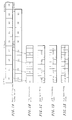
- FIGS. 1A through 1E are illustrative of the manner in which video data for an NVOD system according to an embodiment of the present invention is generated.
- Video data to be broadcast in the NVOD system which is recorded on a magnetooptical disk (MO) or a hard disk (HD), for example, is generated from a video movie material according to a process described below.
- MO magnetooptical disk
- HD hard disk
- FIG. 1A shows digital data of an original video movie material which is 120 minutes long.
- the digital video data is divided into four equal data segments A, B, C, D, and each of the four equal data segments A, B, C, D is further divided into four data units each 7.5 minutes long. Therefore, the digital video data is composed of data units A0, A1, A2, A3, B0, B1, ⁇ , D2, D3.
- video data for the NVOD system shown in FIG. 1E is generated according to four recording passes shown in FIGS. 1B through 1E.
- the data units A0, A1, A2, A3 from the original video data are compressed according to a high-efficient coding process such as MPEG2, for example, and then discretely recorded real-time at initial regions, respectively, of four divided areas of an MO, HD, or the like, for example.
- a high-efficient coding process such as MPEG2, for example
- the data units B0, B1, B2, B3 are similarly compressed, and then recorded real-time at respective regions adjacent to the regions where the data units A0, A1, A2, A3 have already been recorded.
- the data units C0, C1, C2, C3 are similarly compressed, and then recorded real-time at respective regions adjacent to the regions where the data units B0, B1, B2, B3 have already been recorded.
- the data units D0, D1, D2, D3 are similarly compressed, and then recorded real-time at respective regions adjacent to the regions where the data units C0, C1, C2, C3 have already been recorded.
- the four recording passes thus generate compressed data for the NVOD system, whose data units are arranged in a different sequence from the sequence of the data units of the original video data.
- the video data thus generated serve as video data for the NVOD system.
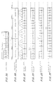
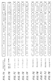
- a process of broadcasting the video movie by sequentially transmitting the video data for the NVOD system at certain time intervals in a plurality of channels (four channels in the embodiment) will be described below with reference to FIGS. 2A through 2F.
- FIG. 2A shows the compressed and recorded video data for the NVOD system shown in FIG. 1E.
- FIG. 2B shows reproduced data generated by successively repeatedly reproducing the video data shown in FIG. 2A.
- the video data shown in FIG. 2A is repeatedly reproduced successively at a high rate of one block per 30 minutes, one block comprising the original video data that is 120 minutes long. It is important to note here that the recording data of one block contains all the reproduced data of the original video data.
- FIGS. 2C through 2F show video movie data sequentially outputted from the repeatedly reproduced data at certain time intervals in channels #1 ⁇ #4.
- the compressed data A0, A1, A2, A3 are intermittently read from the first 30-minutes block of the repeatedly reproduced data shown in FIG. 2B, and buffered to produce video data A0, A1, A2, A3 of first 30 minutes of the video movie. Since the first block of successively reproduced data contains all the data of the video movie, it is possible to reproduce arbitrary video data from the first block.
- the compressed data B0, B1, B2, B3 are intermittently read from the second 30-minutes block, and buffered to produce video data B0, B1, B2, B3 of next 30 minutes of the video movie.
- the compressed data C0, C1, C2, C3 are intermittently read from the third 30-minutes block, and buffered to produce video data C0, C1, C2, C3 of next 30 minutes of the video movie.
- the compressed data D0, D1, D2, D3 are intermittently read from the fourth 30-minutes block, and buffered to produce video data D0, D1, D2, D3 of next 30 minutes of the video movie.
- the video movie which is the same as the video data shown in FIG. 1A is reproduced in its entirety in the channel #1.
- video data A0, A1, A2, A3 of first 30 minutes of the video movie are produced from the compressed data A0, A1, A2, A3 of the second block shown in FIG. 2B
- next video data B0, B1, B2, B3 of next 30 minutes of the video movie are produced from the compressed data B0, B1, B2, B3 of the third block
- next video data C0, C1, C2, C3 of next 30 minutes of the video movie are produced from the compressed data C0, C1, C2, C3 of the fourth block
- next video data D0, D1, D2, D3 of next 30 minutes of the video movie are produced from the compressed data D0, D1, D2, D3 of the fifth block.
- the video movie is reproduced in the channel #2 which starts 30 minutes later than the channel #1.
- the video movie is reproduced in the channel #3 which starts 30 minutes later than the channel #2
- the video movie is reproduced in the channel #4 which starts 30 minutes later than the channel #3.
- the block of the video data shown in FIG. 2A is repeatedly reproduced successively at a high rate as shown in FIG. 2B. Therefore, as shown in FIGS. 2C ⁇ 2F, the video movie starts again in the channel #1 which starts 30 minutes later than the channel #4. Similarly, the video movie sequentially starts in the channels #2, #3, #4 at successive time intervals of 30 minutes.
- the recording medium for broadcasting video data in the NVOD system comprises a magnetooptical disk (MO) or a hard disk (HD), for example.
- the recording process shown in FIGS. 1A through 1E and the reproducing process shown in FIGS. 2A through 2E may be modified on the basis of the capability of a magnetooptical disk drive or a hard disk drive. More specifically, since the performance of recent hard disk drives is greatly improved, data recorded on a hard disk can be reproduced at a relatively high bit rate compared with the bit rate at which the data was recorded. Therefore, in the recording process shown in FIGS.
- the video data may be recorded directly on a hard disk without relying on the compression technology such as MPEG2 or the like, producing a recording medium for the NVOD system (see FIG. 1E), and in the reproducing process shown in FIGS. 2A through 2E, the recorded video data may be reproduced at a high rate such as a quadruple rate, for example.
- the video data may be compressed according to a moving image compression process such as MPEG2 to reduce the amount of data, and may be stored as compressed data on a hard disk. If the compression ratio is 1/10, then when the compressed data is reproduced at a normal rate, it is reproduced at a rate ten times higher than the normal rate in terms of the original video data.
- a moving image compression process such as MPEG2
- a process of time compression may also be employed. Specifically, in the recording process shown in FIGS. 1A through 1E, the video data may be time-compressed to 1/4. In the reproducing process, the time-compressed video data may be reproduced at a normal rate. As a result, the video data may be reproduced at a quadruple rate in terms of the original video data.
- the above processes may be combined with each other.
- the above processes may be used to reproduce the video data at a quadruple rate, for example, in terms of the original video data, compared with the recording rate in the recording process shown in FIGS. 1A through 1E.
- the reproduction of the video data at a high rate as described herein includes all recording and reproducing processes described above.
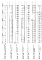
- NVOD system for incorporating CM video programs, promotion video programs, or like into a video movie program based on the same NVOD system video data as described above, and sequentially transmitting the video data at certain time intervals into a plurality of channels will be described below with reference to FIGS. 3A through 3G.
- the NVOD system In order to equalize time intervals at which the video movie data is transmitted into the channels, the NVOD system has five channels, one more channel than the channels shown in FIGS. 2A through 2F.
- FIG. 3A shows the repeatedly reproduced data which is the same as the data shown in FIG. 2B.
- the recording data which has been compressed to 30 minutes from a video movie that is 120 minutes long is used as one block and repeatedly reproduced at a high rate.
- FIG. 3B shows the data of promotion video programs stored in a CM & Promo. server (see “19" in FIG. 6).
- the data include promotion video data Promo. 1, Promo. 2, Promo. 3, Promo. 4, Promo. 5, ⁇ , each recorded as one block.
- the promotion video data Promo. 1 ⁇ Promo. 5 may be of the same contents.
- FIGS. 3C through 3G show video movie data containing promotion video data, which are sequentially transmitted at certain time intervals in channels #1 ⁇ #5.
- the promotion video data Promo. 1 is read from the output data from the CM & Promo. server shown in FIG. 3B, and outputted before the video movie starts being broadcast. Thereafter, the video movie is reproduced in the same manner as described above with reference to FIGS. 2A through 2F.
- the data A0, A1, A2, A3 are intermittently read from the second block shown in FIG. 3A, and expanded to produce video data A0, A1, A2, A3 of 30 minutes.
- the data B0, B1, B2, B3 are intermittently read from the third block shown in FIG. 3A, and expanded to produce video data B0, B1, B2, B3 of 30 minutes.
- the data C0, C1, C2, C3 are intermittently read from the fourth block shown in FIG. 3A, and expanded to produce video data C0, C1, C2, C3 of 30 minutes.
- the data D0, D1, D2, D3 are intermittently read from the fifth block shown in FIG. 3A, and expanded to produce video data D0, D1, D2, D3 of 30 minutes.
- the promotion video data Promo. 1 is broadcast before the video movie starts being broadcast, and thereafter, the video movie is reproduced in its entirety in the same manner as shown in FIG. 2C.
- the promotion video data Promo. 2 is outputted from the output data from the CM & Promo. server shown in FIG. 3B, 30 minutes later than the channel #2.
- video data A0, A1, A2, A3 of the first 30 minutes are produced from the data A0, A1, A2, A3 of the third block shown in FIG. 3A.
- video data B0, B1, B2, B3 of the next 30 minutes are produced from the data B0, B1, B2, B3 of the fourth block shown in FIG. 3A.
- video data C0, C1, C2, C3 of the next 30 minutes are produced from the data C0, C1, C2, C3 of the fifth block shown in FIG. 3A.
- video data D0, D1, D2, D3 of the next 30 minutes are produced from the data D0, D1, D2, D3 of the sixth block shown in FIG. 3A.
- the promotion video data Promo. 2 is incorporated before the video movie is started, and the same video movie as shown in FIG. 1A which starts 30 minutes later than the channel #1 is reproduced in its entirety.
- the promotion video data Promo. 3 is incorporated before the video movie is started, and the video movie which starts 30 minutes later than the channel #2 is outputted in its entirety.
- the promotion video data Promo. 4 is incorporated before the video movie is started, and the video movie which starts 30 minutes later than the channel #3 is outputted in its entirety.
- the promotion video data Promo. 5 is incorporated before the video movie is started, and the video movie which starts 30 minutes later than the channel #4 is outputted in its entirety.
- a total of five channels are provided for broadcasting a video movie which is 120 minutes long, and the user may select, at a desired time, a channel for the video movie that starts immediately after the desired time, for viewing the video movie in which a CM video program or the like is incorporated, without having to wait for more than 30 minutes.
- a maximum possible waiting time is about 7.5 minutes.
- a CM video program or the like is incorporated prior to the start of the first block of a video movie.
- the incorporation of a CM video program or the like is carried out by switching operation of a matrix switcher 15 which will be described later on with reference to FIG. 6. Therefore, a CM video program or the like can be incorporated as desired between arbitrary blocks of video data.
- FIG. 4 shows by way of example a video data generating apparatus for generating video data according to the four recording passes described above with reference to FIGS. 1B through 1E.
- the video data generating apparatus comprises a video reproducer 1 such as a video disk player for reproducing video data recorded on a video disk, for example, an encoder 3 for effecting a high-efficiency coding process on video data reproduced by the video reproducer 1, an FIFO memory 5 for buffering a compressed signal from the encoder 3, a controller 7 for reading a compressed digital signal from the FIFO memory 5, and a high-speed digital recording device 9 such as a magnetooptical disk drive (MOD) or a hard disk drive (HDD) for recording the compressed digital signal from the controller 7 under the control of the controller 7.
- a video reproducer 1 such as a video disk player for reproducing video data recorded on a video disk
- an encoder 3 for effecting a high-efficiency coding process on video data reproduced by the video reproducer 1
- an FIFO memory 5 for buffer
- the video reproducer 1 is a device for reproducing video data.
- the video reproducer 1 is controlled by a control signal from the controller 7 to access a given recording position for controlling the time to start reproducing the recorded video data.
- the video reproducer 1 can also be controlled in synchronism with an external synchronising signal 13 when necessary.
- the encoder 3 comprises a real-time video compressor for bandwidth-compressing video data according to a moving image compression process such as MPEG2.
- the FIFO memory 5, or a first-in, first-out memory serves to buffer the compressed video data by writing and reading the compressed video data at given times in response to a timing signal 6 from the controller 7, and transmit the read video data to the controller 7.
- the controller 7 controls the time to start reproducing the recorded video data with the video reproducer 1, determines a time to read the compressed digital signal from the FIFO memory 5, and also determines a time to write the compressed digital signal in a given area of the recording medium with the high-speed digital recording device 9.
- the high-speed digital recording device 9 comprises an MOD (magnetooptical disk drive) or an HDD (hard disk drive), for example, for recording at a high density the digital video data from the controller 7 in positions described above with reference to FIGS. 1B through 1E.
- MOD magnetooptical disk drive
- HDD hard disk drive
- the video data generating apparatus operates as follows: In the first recording pass initiated by a reproduction start control signal supplied from the controller 7 to the video reproducer 1, the data units A0, A1, A2, A3 of the first 30 minutes which have been reproduced by the video reproducer 1 are compressed by the encoder 3, and the compressed data are sent to the FIFO memory 5, from which the data are read at given times according to a timing signal from the controller 7 and recorded as compressed data A0, A1, A2, A3 in initial portions of respective four equal areas (see FIG. 1B) of the recording medium in the high-speed digital recording device 9.
- the data B0, B1, B2, B3 are recorded as compressed data B0, B1, B2, B3 in the respective areas as shown in FIG. 1C.
- the data C0, C1, C2, C3 are recorded as compressed data C0, C1, C2, C3 in the respective areas as shown in FIG. 1D.
- the data D0, D1, D2, D3 are recorded as compressed data D0, D1, D2, D3 in the respective areas as shown in FIG. 1E.
- the high-density data as shown in FIG. 1E are stored in the high-speed digital recording device 9.
- FIG. 5 shows a high-density recording video data generating apparatus for use in generating such high-density video data.
- the high-density recording video data generating apparatus comprises four of the video data generating apparatus shown in FIG. 4 which are connected parallel to each other.
- the high-density recording video data generating apparatus comprises video reproducers 1-1, ⁇ , 1-4 for reproducing original video data, encoders 3-1, ⁇ , 3-4 for compressing video data reproduced by the video reproducers 1-1, ⁇ , 1-4, FIFO memories 5-1, ⁇ , 5-4 for buffering compressed signals from the encoders 3-1, ⁇ , 3-4, a controller 7 for reading compressed digital signals from the FIFO memories 5-1, ⁇ , 5-4 and controlling the video disk devices, and a high-speed digital recording device 9 such as an MOD or an HDD for recording the compressed digital signals read by the controller 7.
- a high-speed digital recording device 9 such as an MOD or an HDD for recording the compressed digital signals read by the controller 7.
- the video reproducers 1-1, ⁇ , 1-4 output respective video data 0, 30, 60, 90 minutes after the control signal 11 starts reproducing the video data.
- the encoders 3-1, ⁇ , 3-4 compress the video data real-time. Specifically, the encoder 3-1 is supplied with the video data A0, A1, A2, A3, compresses them, and writes the compressed video data in the FIFO memory 5-1.
- the encoder 3-2 is supplied with the video data B0, B1, B2, B3, compresses them, and writes the compressed video data in the FIFO memory 5-2.
- the encoder 3-3 is supplied with the video data C0, C1, C2, C3, compresses them, and writes the compressed video data in the FIFO memory 5-3.
- the encoder 3-4 is supplied with the video data D0, D1, D2, D3, compresses them, and writes the compressed video data in the FIFO memory 5-4.
- the controller 7 reads the compressed digital signals from the FIFO memories 5-1, ⁇ , 5-4 in the order shown in FIG. 1E, and writes the compressed digital signals in the MOD/HDD 9 at a high rate.
- the high-density recording video data generating apparatus generates NVOD system video data recorded at a high density as shown in FIG. 1E according a single recording pass.
- An actually proposed 16-channel NVOD system has 16 video reproducers 1, 16 encoders 3, and 16 FIFO memories 5 which are connected parallel to each other.
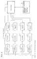
- FIG. 6 shows by way of example an apparatus for incorporating a CM video program or the like in an NVOD system.
- the apparatus comprises a high-speed digital reproducing device 11 such as an MOD or an HDD, a CM & Promo. server 19 for outputting video data such as CM video or promotion video data, FIFO memories 13-1, 13-2, 13-3, 13-4 for buffering compressed data reproduced by the high-speed digital reproducing device 11, a matrix switcher 15 for selectively reading compressed data stored in the FIFO memories 13-1, 13-2, 13-3, 13-4 or compressed data from the CM & Promo.
- a high-speed digital reproducing device 11 such as an MOD or an HDD
- CM & Promo. server 19 for outputting video data such as CM video or promotion video data
- FIFO memories 13-1, 13-2, 13-3, 13-4 for buffering compressed data reproduced by the high-speed digital reproducing device 11
- a matrix switcher 15 for selectively reading compressed data stored in the FIFO memories 13-1, 1
- the apparatus also has a controller 29 for sending a reproduction start synchronizing signal 21 to the high-speed digital reproducing device 11 and the CM & Promo. server 19, a write/read timing signal 25 to the FIFO memories 13-1, 13-2, 13-3, 13-4, and a switching control signal to the matrix switcher 15 to select data to be outputted to the channels #1 ⁇ #5.
- the high-speed digital reproducing device 11 comprises magnetooptical disk drive (MOD) or a hard disk drive (HDD) for successively reproducing at a high rate NVOD system video data which have been recorded at a high density as shown in FIG. 1E.
- MOD magnetooptical disk drive
- HDD hard disk drive
- the CM & Promo. server 19 is one type of video server, and comprises a device for storing and distributing data such as CM video data or the like.
- the CM & Promo. server 19 stores data such as CM video data or the like compressed under the same conditions as video movie blocks, as shown in FIG. 3B, and reproduces and outputs the stored data.
- the FIFO memories 13-1, ⁇ , 13-4, or first-in, first-out memories serve to buffer the compressed video signals from the high-speed digital reproducing device 11 by selectively writing and reading the compressed video signals in response to a control signal from the controller 29 for transmission to the matrix switcher 15.
- the matrix switcher 15 receives the compressed video data from the FIFO memories 13-1, ⁇ , 13-4 or the compressed CM video data or the like from the CM & Promo. server 19, and selectively outputs the received data to the channels in response to a stitching control signal 27 from the controller 29.
- the respective channels may have decoders for decoding the compressed video data from the matrix switcher 15 and outputting the decoded video data to the channels.
- the encoders 17-1, ⁇ , 17-5 add an error-correcting code to the CM video and video movie data from the matrix switcher 15, interleave the data, add a synchronizing signal to the data, and output the data to the respective channels #1 ⁇ #5.
- the apparatus shown in FIG. 6 resides in that the number of channels is one greater than the number of FIFO memories for reading video movie data stored in the high-speed digital reproducing device 11.
- FIGS. 7A through 7K are illustrative of the manner in which the apparatus shown in FIG. 6 operates for incorporating CM video data or the like in an NVOD system.
- FIG. 7A shows compressed video data 12 outputted from the speed digital reproducing device 11 in response to the reproduction start synchronizing signal 21 from the controller 29.
- FIG. 7B shows compressed promotion video data 20 outputted from the CM & Promo. server 19 in response to the reproduction start synchronizing signal 21 from the controller 29.
- FIGS. 7C through 7E show video data outputted from the FIFO memories 13-1, ⁇ , 13-4 which have selectively stored the video data 12 shown in FIG. 7A, in response to the timing signal 25 from the controller 29 as described above with reference to FIG. 6.
- the FIFO memory 13-1 selectively stores compressed data A0 ⁇ A3 from the first block shown in FIG. 7A, compressed data B0 ⁇ B3 from the second block, compressed data C0 ⁇ C3 from the third block, and compressed data D0 ⁇ D3 from the fourth block.
- FIG. 7C the FIFO memory 13-1 selectively stores compressed data A0 ⁇ A3 from the first block shown in FIG. 7A, compressed data B0 ⁇ B3 from the second block, compressed data C0 ⁇ C3 from the third block, and compressed data D0 ⁇ D3 from the fourth block.
- the FIFO memory 13-2 stores compressed data A0 ⁇ A3, B0 ⁇ B3, C0 ⁇ C3, D0 ⁇ D3 at times 30 minutes later than the FIFO memory 13-1.
- the FIFO memory 13-3 stores compressed data A0 ⁇ A3, B0 ⁇ B3, C0 ⁇ C3, D0 ⁇ D3 at times 30 minutes later than the FIFO memory 13-2.
- the FIFO memory 13-4 stores compressed data A0 ⁇ A3, B0 ⁇ B3, C0 ⁇ C3, D0 ⁇ D3 at times 30 minutes later than the FIFO memory 13-3.
- FIGS. 7G through 7K show data 14-1, ⁇ , 14-4 (see FIGS. 7G ⁇ 7F) such as compressed video data from the FIFO memories 13-1, ⁇ , 13-4 and compressed promotion video data 20 from the CM & Promo. server 19, which the matrix switcher 12 has selectively outputted to the channels #1 ⁇ #5 in response to the switching control signal 27 from the controller 29.
- These data comprise video data combined with CM video data or the like, and supplied through the respective encoders 17-1, ⁇ , 17-5 to the respective channels.
- the matrix switcher 15 selectively outputs the data from the CM & Promo. server 19 to the channel #1 for the first 30 minutes.
- the matrix switcher 15 selectively outputs the video data from the FIFO memories 13-1, ⁇ , 13-4 to the respective channels #5, #2, #3, #4.
- the matrix switcher 15 selectively outputs the data from the CM & Promo. server 19 to the channel #2, and at the same time, selectively outputs the video data from the FIFO memories 13-1, ⁇ , 13-4 to the respective channels #5, #1, #3, #4.
- the matrix switcher 15 selectively outputs the data from the CM & Promo. server 19 to the channel #3, and at the same time, selectively outputs the video data from the FIFO memories 13-1, ⁇ , 13-4 to the respective channels #5, #1, #2, #4.
- the matrix switcher 15 selectively outputs the data from the CM & Promo. server 19 to the channel #4, and at the same time, selectively outputs the video data from the FIFO memories 13-1, ⁇ , 13-4 to the respective channels #5, #1, #2, #3.
- the matrix switcher 15 selectively outputs the data from the CM & Promo. server 19 to the channel #5, and at the same time, selectively outputs the video data from the FIFO memories 13-1, ⁇ , 13-4 to the respective channels #4, #1, #2, #3.
- the matrix switcher 15 selectively outputs the data from the CM & Promo. server 19 to the channel #5, and at the same time, selectively outputs the video data from the FIFO memories 13-1, ⁇ , 13-4 to the respective channels #4, #1, #2, #4. Subsequently, the above cycles are repeated.
- the encoders 17-1, ⁇ , 17-5 add an error-correcting code to the data and otherwise process the data, and transmit the data to the users.
- a maximum possible waiting time for the user to start viewing a video movie 120 minutes long, is about 7.5 minutes with 17 channels available. If CM video data or the like is incorporated at two locations in video movie data, then the video movie data can similarly be broadcast by using 18 channels.
- CM video data or the like incorporated at M locations therein with an NVOD system For broadcasting a video movie whose net time is T VIDEO. [minutes] with CM video data or the like incorporated at M locations therein with an NVOD system, if the video data are to be sequentially broadcast at time intervals of about T VIDEO. /N [minutes] that are equal to those with video data with no CM video data or the like incorporated therein, then the video data with CM video data or the like incorporated can be broadcast by increasing the number of channels to N + M. The period of time of the CM video data or the like at each location is kept within T VIDEO. /N [minutes].
- the CM video data or the like is divided into video data whose number is indicated by a value P which is determined as T Promo.
- P is an integer produced by counting the fractions to the decimal point as a whole number) (therefore, the CM video data or the like at each location is at most T VIDEO. /L [minutes] long), and the P blocks of the CM video data or the like are inserted between desired P blocks of the video movie data.
- the insertion is carried out by the matrix switcher 15.
- the video data with CM video data or the like incorporated can be broadcast at time intervals of about T VIDEO. /N [minutes] that are equal to those with video data with no CM video data or the like incorporated therein, by increasing the number of channels to N + M.
- CM video data or promotion video data whose broadcasting time is T Promo. [minutes] are combined with each other, and the video movie data are broadcast sequentially at equal time intervals, then the video movie data are sequentially broadcast at time intervals of T VIDEO. /L [minutes] through the L channels.
- the CM video data or the like is divided into video data whose number is indicated by a value P which is determined as T Promo.
- the storage medium for the data of a video movie and the storage medium for the data of CM video programs or the like are separate from each other, the CM video programs or the like can be updated as desired.
- an NVOD system capable of incorporating additional information programs such as CM video programs, promotion video programs, or the like into main video programs, and a broadcasting method for such an NVOD system.
- an NVOD system which is capable of easily updating additional information programs such as CM video programs, promotion video programs, or the like to be incorporated into main video programs.
Abstract
Description
- The present invention relates to a near video-on-demand system for use in a subscription television broadcasting system which is called a pay television system or a restricted reception system, and a broadcasting method for such a near video-on-demand system.
- In recent years, many video movies, for example, have been broadcast on pay television. When main programs such as video movies are broadcast on pay television, an additional information program such as a CM (commercial) video program, a promotion video program, or the like is broadcast between main programs, i.e., before the start of a video movie or after the end of a video movie, but not inserted in the middle of a video movie.
- Present pay television programs are broadcast through a single channel, and CM video program, promotion video programs, or the like (hereinafter referred to as "CM video programs") are broadcast together before the start of a video movie or after the end of a video movie. Since video movie materials and CM video program materials are different from each other, it is easy to update CM video program materials.
- Recently, there have been demands for a video-on-demand (VOD) system service as one type of pay television which allows users to view a video program from its beginning at any time they want. Various studies on VOD systems show, however, that since a complete VOD system needs extremely many channels depending on the number of subscribing users, it is difficult to collect the investment made in the VOD system. For this reason, the VOD system is not among various types of pay television that are being studied.
- One recent alternative to the VOD system is a service in which video programs of the same contents are sequentially broadcast at certain time intervals ranging from 5 to 15 minutes, for example, in a limited number of frequency channels, and the user selects one of the channels which is most convenient for them at the time of starting to use the service, so that the user can see the video program from the beginning at a desired time though he or she may have to wait a little while. This service is referred to as a near video-on-demand (NVOD) system.
- The NVOD system has one problem to be solved yet as to how CM video programs are incorporated into video programs broadcast in the channels. The very nature of such CM video programs requires them to be updated at appropriate intervals so that they will provide latest commercial information.
- According to one solution, as many sets of video movie materials and CM video materials as the number of the available channels are prepared, and independently broadcast at certain time intervals in the respective channels. If, however, a pay television broadcasting station is able to establish an NVOD system which broadcasts only one set of video movie materials and CM video materials at certain time intervals in a plurality of channels, then such an NVOD system will be highly convenient and inexpensive for users. It is desirable in such an NVOD system to be able to separate CM video materials from video movie materials for easily updating the CM video materials at appropriate times.
- Therefore, it is an object of the present invention to provide an NVOD system capable of incorporating CM video programs, promotion video programs, or the like into video programs, and a broadcasting method for such an NVOD system.
- Another object of the present invention is to provide an NVOD system which is capable of easily updating CM video programs, promotion video programs, or the like to be incorporated into video programs.
- According to the present invention, a near video-on-demand system comprises control means, high-speed digital reproducing means responsive to a control signal from the control means, for reproducing at a high rate a plurality of video-on-demand system recording data divided from digital data of a main program and recorded at discrete areas, an additional information program data server for reproducing data of an additional information program in response to a control signal from the control means, buffer means responsive to a control signal from the control means, for selectively writing the video-on-demand system recording data from the high-speed digital reproducing means and reading the video-on-demand system recording data, and matrix switcher means responsive to a control signal from the control means, for selectively outputting main program data from the buffer means and additional information data from the additional information program data server, and sequentially transmitting the main program data with the additional information data incorporating therein in a plurality of channels.
- According to the present invention, furthermore, a method of broadcasting a main program whose net time is TVIDEO. with an additional information program incorporated at M locations therein, using a near video-on-demand system, comprises the step of increasing the number of channels from the conventional number N of channels to N + M in order to insert the additional information program in the M locations, so that the main program with the additional information program incorporated therein will sequentially be broadcast at the same time intervals as when the main program with the additional information program not incorporated therein is broadcast.
-
- FIGS. 1A through 1E are diagrams illustrative of the manner in which high-density recording data for an NVOD system is generated;
- FIGS. 2A through 2F are diagrams illustrative of a process of broadcasting a video movie with no CM video and promotion video programs incorporated therein in a four-channel NVOD system;
- FIGS. 3A through 3G are diagrams illustrative of a process of broadcasting a video movie with CM video and promotion video programs incorporated therein in a five-channel NVOD system;
- FIG. 4 is a block diagram of an apparatus for generating high-density recording data for an NVOD system as shown in FIG. 1;
- FIG. 5 is a block diagram of another apparatus for generating high-density recording data for an NVOD system as shown in FIG. 1;
- FIG. 6 is a block diagram of an apparatus for incorporating a CM video or promotion video program in a five-channel NVOD system; and
- FIGS. 7A through 7K are diagrams illustrative of the manner in which the apparatus shown in FIG. 6 operates.
- Embodiments of an NVOD system capable of incorporating CM video programs, promotion video programs, or the like into video programs, and a broadcasting method for such an NVOD system will be described below with reference to the accompanying drawings.
- FIGS. 1A through 1E are illustrative of the manner in which video data for an NVOD system according to an embodiment of the present invention is generated. Video data to be broadcast in the NVOD system, which is recorded on a magnetooptical disk (MO) or a hard disk (HD), for example, is generated from a video movie material according to a process described below.
- FIG. 1A shows digital data of an original video movie material which is 120 minutes long. The digital video data is divided into four equal data segments A, B, C, D, and each of the four equal data segments A, B, C, D is further divided into four data units each 7.5 minutes long. Therefore, the digital video data is composed of data units A0, A1, A2, A3, B0, B1, ···, D2, D3.
- From the original video data shown in FIG. 1A, video data for the NVOD system shown in FIG. 1E is generated according to four recording passes shown in FIGS. 1B through 1E.
- As shown in FIG. 1B, in the first recording pass, the data units A0, A1, A2, A3 from the original video data are compressed according to a high-efficient coding process such as MPEG2, for example, and then discretely recorded real-time at initial regions, respectively, of four divided areas of an MO, HD, or the like, for example.
- Then, as shown in FIG. 1C, in the second recording pass, the data units B0, B1, B2, B3 are similarly compressed, and then recorded real-time at respective regions adjacent to the regions where the data units A0, A1, A2, A3 have already been recorded.
- Then, as shown in FIG. 1D, in the third recording pass, the data units C0, C1, C2, C3 are similarly compressed, and then recorded real-time at respective regions adjacent to the regions where the data units B0, B1, B2, B3 have already been recorded.
- Thereafter, as shown in FIG. 1E, in the fourth recording pass, the data units D0, D1, D2, D3 are similarly compressed, and then recorded real-time at respective regions adjacent to the regions where the data units C0, C1, C2, C3 have already been recorded.
- The four recording passes thus generate compressed data for the NVOD system, whose data units are arranged in a different sequence from the sequence of the data units of the original video data. The video data thus generated serve as video data for the NVOD system.
- A process of broadcasting the video movie by sequentially transmitting the video data for the NVOD system at certain time intervals in a plurality of channels (four channels in the embodiment) will be described below with reference to FIGS. 2A through 2F.
- FIG. 2A shows the compressed and recorded video data for the NVOD system shown in FIG. 1E.
- FIG. 2B shows reproduced data generated by successively repeatedly reproducing the video data shown in FIG. 2A. The video data shown in FIG. 2A is repeatedly reproduced successively at a high rate of one block per 30 minutes, one block comprising the original video data that is 120 minutes long. It is important to note here that the recording data of one block contains all the reproduced data of the original video data.
- FIGS. 2C through 2F show video movie data sequentially outputted from the repeatedly reproduced data at certain time intervals in
channels # 1 ∼ #4. - In the
channel # 1, as shown in FIG. 2C, the compressed data A0, A1, A2, A3 are intermittently read from the first 30-minutes block of the repeatedly reproduced data shown in FIG. 2B, and buffered to produce video data A0, A1, A2, A3 of first 30 minutes of the video movie. Since the first block of successively reproduced data contains all the data of the video movie, it is possible to reproduce arbitrary video data from the first block. - Then, the compressed data B0, B1, B2, B3 are intermittently read from the second 30-minutes block, and buffered to produce video data B0, B1, B2, B3 of next 30 minutes of the video movie.
- Then, the compressed data C0, C1, C2, C3 are intermittently read from the third 30-minutes block, and buffered to produce video data C0, C1, C2, C3 of next 30 minutes of the video movie.
- Then, the compressed data D0, D1, D2, D3 are intermittently read from the fourth 30-minutes block, and buffered to produce video data D0, D1, D2, D3 of next 30 minutes of the video movie.
- According to the above broadcasting process, the video movie which is the same as the video data shown in FIG. 1A is reproduced in its entirety in the
channel # 1. - Similarly, in the
channel # 2, as shown in FIG. 2D, video data A0, A1, A2, A3 of first 30 minutes of the video movie are produced from the compressed data A0, A1, A2, A3 of the second block shown in FIG. 2B, next video data B0, B1, B2, B3 of next 30 minutes of the video movie are produced from the compressed data B0, B1, B2, B3 of the third block, next video data C0, C1, C2, C3 of next 30 minutes of the video movie are produced from the compressed data C0, C1, C2, C3 of the fourth block, and next video data D0, D1, D2, D3 of next 30 minutes of the video movie are produced from the compressed data D0, D1, D2, D3 of the fifth block. In this manner, the video movie is reproduced in thechannel # 2 which starts 30 minutes later than thechannel # 1. - Likewise, as shown in FIG. 2E, the video movie is reproduced in the
channel # 3 which starts 30 minutes later than thechannel # 2, and as shown in FIG. 2F, the video movie is reproduced in thechannel # 4 which starts 30 minutes later than thechannel # 3. - In the NVOD system, the block of the video data shown in FIG. 2A is repeatedly reproduced successively at a high rate as shown in FIG. 2B. Therefore, as shown in FIGS. 2C ∼ 2F, the video movie starts again in the
channel # 1 which starts 30 minutes later than thechannel # 4. Similarly, the video movie sequentially starts in thechannels # 2, #3, #4 at successive time intervals of 30 minutes. - The process of recording an original video movie material at scattered locations on a hard disk or the like to generate a recording medium for the NVOD system and playing back the recording medium, as described above with reference to FIGS. 1A ∼ 1E and 2A ∼ 2F is described in detail in U.S. patent application No. 448,243 filed on May 23, 1995 and assigned to the same assignee as the present application (corresponding to Japanese patent applications Nos. 6-112,940 and 6-119,342). Reference should be made to the above application if necessary.
- The recording medium for broadcasting video data in the NVOD system comprises a magnetooptical disk (MO) or a hard disk (HD), for example. The recording process shown in FIGS. 1A through 1E and the reproducing process shown in FIGS. 2A through 2E may be modified on the basis of the capability of a magnetooptical disk drive or a hard disk drive. More specifically, since the performance of recent hard disk drives is greatly improved, data recorded on a hard disk can be reproduced at a relatively high bit rate compared with the bit rate at which the data was recorded. Therefore, in the recording process shown in FIGS. 1A through 1E, the video data may be recorded directly on a hard disk without relying on the compression technology such as MPEG2 or the like, producing a recording medium for the NVOD system (see FIG. 1E), and in the reproducing process shown in FIGS. 2A through 2E, the recorded video data may be reproduced at a high rate such as a quadruple rate, for example.
- Furthermore, in the recording process shown in FIGS. 1A through 1E, the video data may be compressed according to a moving image compression process such as MPEG2 to reduce the amount of data, and may be stored as compressed data on a hard disk. If the compression ratio is 1/10, then when the compressed data is reproduced at a normal rate, it is reproduced at a rate ten times higher than the normal rate in terms of the original video data.
- A process of time compression may also be employed. Specifically, in the recording process shown in FIGS. 1A through 1E, the video data may be time-compressed to 1/4. In the reproducing process, the time-compressed video data may be reproduced at a normal rate. As a result, the video data may be reproduced at a quadruple rate in terms of the original video data. The above processes may be combined with each other.
- At any rate, the above processes may be used to reproduce the video data at a quadruple rate, for example, in terms of the original video data, compared with the recording rate in the recording process shown in FIGS. 1A through 1E. Unless otherwise specified, the reproduction of the video data at a high rate as described herein includes all recording and reproducing processes described above.
- In the above embodiment, there are four channels available for a video movie that is 120 minutes long, and the user can select one of the four channels in which the video movie starts from the beginning at any desired time. Therefore, the user can start viewing the video movie without waiting for more than 30 minutes at maximum.
- Generally, if a video movie which is TVIDEO. minutes long is sequentially broadcast at equal time intervals in an NVOD system with N channels, then the user can start viewing the video movie from the beginning at a maximum possible waiting time of

- An NVOD system for incorporating CM video programs, promotion video programs, or like into a video movie program based on the same NVOD system video data as described above, and sequentially transmitting the video data at certain time intervals into a plurality of channels will be described below with reference to FIGS. 3A through 3G. In order to equalize time intervals at which the video movie data is transmitted into the channels, the NVOD system has five channels, one more channel than the channels shown in FIGS. 2A through 2F.
- FIG. 3A shows the repeatedly reproduced data which is the same as the data shown in FIG. 2B. The recording data which has been compressed to 30 minutes from a video movie that is 120 minutes long is used as one block and repeatedly reproduced at a high rate.
- FIG. 3B shows the data of promotion video programs stored in a CM & Promo. server (see "19" in FIG. 6). The data include promotion video data Promo. 1, Promo. 2, Promo. 3, Promo. 4, Promo. 5, ···, each recorded as one block. When the promotion video data Promo. 1 ∼ Promo. 5 are broadcast, they have to be at most 30 minutes long. The promotion video data Promo. 1 ∼ Promo. 5 may be of the same contents.
- FIGS. 3C through 3G show video movie data containing promotion video data, which are sequentially transmitted at certain time intervals in
channels # 1 ∼ #5. - In the
channel # 1, as shown in FIG. 3C, the promotion video data Promo. 1 is read from the output data from the CM & Promo. server shown in FIG. 3B, and outputted before the video movie starts being broadcast. Thereafter, the video movie is reproduced in the same manner as described above with reference to FIGS. 2A through 2F. Specifically, in the next 30 minutes, the data A0, A1, A2, A3 are intermittently read from the second block shown in FIG. 3A, and expanded to produce video data A0, A1, A2, A3 of 30 minutes. Then, in the next 30 minutes, the data B0, B1, B2, B3 are intermittently read from the third block shown in FIG. 3A, and expanded to produce video data B0, B1, B2, B3 of 30 minutes. Then, in the next 30 minutes, the data C0, C1, C2, C3 are intermittently read from the fourth block shown in FIG. 3A, and expanded to produce video data C0, C1, C2, C3 of 30 minutes. Then, in the next 30 minutes, the data D0, D1, D2, D3 are intermittently read from the fifth block shown in FIG. 3A, and expanded to produce video data D0, D1, D2, D3 of 30 minutes. - In the
channel # 1, therefore, as shown in FIG. 3C, the promotion video data Promo. 1 is broadcast before the video movie starts being broadcast, and thereafter, the video movie is reproduced in its entirety in the same manner as shown in FIG. 2C. - Similarly, in the
channel # 2, as shown in FIG. 3D, the promotion video data Promo. 2 is outputted from the output data from the CM & Promo. server shown in FIG. 3B, 30 minutes later than thechannel # 2. In the next 30 minutes, video data A0, A1, A2, A3 of the first 30 minutes are produced from the data A0, A1, A2, A3 of the third block shown in FIG. 3A. Then, in the next 30 minutes, video data B0, B1, B2, B3 of the next 30 minutes are produced from the data B0, B1, B2, B3 of the fourth block shown in FIG. 3A. Then, in the next 30 minutes, video data C0, C1, C2, C3 of the next 30 minutes are produced from the data C0, C1, C2, C3 of the fifth block shown in FIG. 3A. Then, in the next 30 minutes, video data D0, D1, D2, D3 of the next 30 minutes are produced from the data D0, D1, D2, D3 of the sixth block shown in FIG. 3A. Thus, in thechannel # 2, the promotion video data Promo. 2 is incorporated before the video movie is started, and the same video movie as shown in FIG. 1A which starts 30 minutes later than thechannel # 1 is reproduced in its entirety. - Likewise, in the
channel # 3, as shown in FIG. 3E, the promotion video data Promo. 3 is incorporated before the video movie is started, and the video movie which starts 30 minutes later than thechannel # 2 is outputted in its entirety. In thechannel # 4, as shown in FIG. 3F, the promotion video data Promo. 4 is incorporated before the video movie is started, and the video movie which starts 30 minutes later than thechannel # 3 is outputted in its entirety. In thechannel # 5, as shown in FIG. 3G, the promotion video data Promo. 5 is incorporated before the video movie is started, and the video movie which starts 30 minutes later than thechannel # 4 is outputted in its entirety. - In the above embodiment, a total of five channels, one more channel than the channels shown in FIGS. 2A through 2F, are provided for broadcasting a video movie which is 120 minutes long, and the user may select, at a desired time, a channel for the video movie that starts immediately after the desired time, for viewing the video movie in which a CM video program or the like is incorporated, without having to wait for more than 30 minutes.
- As described with reference to FIGS. 2A through 2F, since the NVOD system that has actually been proposed has 16 channels, a maximum possible waiting time is about 7.5 minutes.
- In the embodiment shown in FIGS. 3A through 3G, a CM video program or the like is incorporated prior to the start of the first block of a video movie. The incorporation of a CM video program or the like is carried out by switching operation of a matrix switcher 15 which will be described later on with reference to FIG. 6. Therefore, a CM video program or the like can be incorporated as desired between arbitrary blocks of video data.
- If a video movie which is TVIDEO. minutes long with a CM video program or the like incorporated at M locations therein is sequentially broadcast at equal time intervals in an NVOD system with N + M channels, then the user can start viewing the video movie from the beginning at a maximum possible waiting time of

- FIG. 4 shows by way of example a video data generating apparatus for generating video data according to the four recording passes described above with reference to FIGS. 1B through 1E. The video data generating apparatus comprises a
video reproducer 1 such as a video disk player for reproducing video data recorded on a video disk, for example, anencoder 3 for effecting a high-efficiency coding process on video data reproduced by thevideo reproducer 1, anFIFO memory 5 for buffering a compressed signal from theencoder 3, acontroller 7 for reading a compressed digital signal from theFIFO memory 5, and a high-speeddigital recording device 9 such as a magnetooptical disk drive (MOD) or a hard disk drive (HDD) for recording the compressed digital signal from thecontroller 7 under the control of thecontroller 7. - The
video reproducer 1 is a device for reproducing video data. Thevideo reproducer 1 is controlled by a control signal from thecontroller 7 to access a given recording position for controlling the time to start reproducing the recorded video data. Thevideo reproducer 1 can also be controlled in synchronism with anexternal synchronising signal 13 when necessary. - The
encoder 3 comprises a real-time video compressor for bandwidth-compressing video data according to a moving image compression process such as MPEG2. - The
FIFO memory 5, or a first-in, first-out memory, serves to buffer the compressed video data by writing and reading the compressed video data at given times in response to atiming signal 6 from thecontroller 7, and transmit the read video data to thecontroller 7. - The
controller 7 controls the time to start reproducing the recorded video data with thevideo reproducer 1, determines a time to read the compressed digital signal from theFIFO memory 5, and also determines a time to write the compressed digital signal in a given area of the recording medium with the high-speeddigital recording device 9. - The high-speed
digital recording device 9 comprises an MOD (magnetooptical disk drive) or an HDD (hard disk drive), for example, for recording at a high density the digital video data from thecontroller 7 in positions described above with reference to FIGS. 1B through 1E. - The video data generating apparatus operates as follows: In the first recording pass initiated by a reproduction start control signal supplied from the
controller 7 to thevideo reproducer 1, the data units A0, A1, A2, A3 of the first 30 minutes which have been reproduced by thevideo reproducer 1 are compressed by theencoder 3, and the compressed data are sent to theFIFO memory 5, from which the data are read at given times according to a timing signal from thecontroller 7 and recorded as compressed data A0, A1, A2, A3 in initial portions of respective four equal areas (see FIG. 1B) of the recording medium in the high-speeddigital recording device 9. - Similarly, in the second recording pass, the data B0, B1, B2, B3 are recorded as compressed data B0, B1, B2, B3 in the respective areas as shown in FIG. 1C. In the third recording pass, the data C0, C1, C2, C3 are recorded as compressed data C0, C1, C2, C3 in the respective areas as shown in FIG. 1D. In the fourth recording pass, the data D0, D1, D2, D3 are recorded as compressed data D0, D1, D2, D3 in the respective areas as shown in FIG. 1E. In this manner, the high-density data as shown in FIG. 1E are stored in the high-speed
digital recording device 9. - It is possible to generate high-density video data in the first recording pass. FIG. 5 shows a high-density recording video data generating apparatus for use in generating such high-density video data. Basically, the high-density recording video data generating apparatus comprises four of the video data generating apparatus shown in FIG. 4 which are connected parallel to each other. Specifically, the high-density recording video data generating apparatus comprises video reproducers 1-1, ···, 1-4 for reproducing original video data, encoders 3-1, ···, 3-4 for compressing video data reproduced by the video reproducers 1-1, ···, 1-4, FIFO memories 5-1, ···, 5-4 for buffering compressed signals from the encoders 3-1, ···, 3-4, a
controller 7 for reading compressed digital signals from the FIFO memories 5-1, ···, 5-4 and controlling the video disk devices, and a high-speeddigital recording device 9 such as an MOD or an HDD for recording the compressed digital signals read by thecontroller 7. - The video reproducers 1-1, ···, 1-4 output
respective video data control signal 11 starts reproducing the video data. - The encoders 3-1, ···, 3-4 compress the video data real-time. Specifically, the encoder 3-1 is supplied with the video data A0, A1, A2, A3, compresses them, and writes the compressed video data in the FIFO memory 5-1. The encoder 3-2 is supplied with the video data B0, B1, B2, B3, compresses them, and writes the compressed video data in the FIFO memory 5-2. The encoder 3-3 is supplied with the video data C0, C1, C2, C3, compresses them, and writes the compressed video data in the FIFO memory 5-3. The encoder 3-4 is supplied with the video data D0, D1, D2, D3, compresses them, and writes the compressed video data in the FIFO memory 5-4.
- The
controller 7 reads the compressed digital signals from the FIFO memories 5-1, ···, 5-4 in the order shown in FIG. 1E, and writes the compressed digital signals in the MOD/HDD 9 at a high rate. The high-density recording video data generating apparatus generates NVOD system video data recorded at a high density as shown in FIG. 1E according a single recording pass. An actually proposed 16-channel NVOD system has 16video reproducers 1, 16encoders 3, and 16FIFO memories 5 which are connected parallel to each other. - FIG. 6 shows by way of example an apparatus for incorporating a CM video program or the like in an NVOD system. The apparatus comprises a high-speed digital reproducing
device 11 such as an MOD or an HDD, a CM & Promo.server 19 for outputting video data such as CM video or promotion video data, FIFO memories 13-1, 13-2, 13-3, 13-4 for buffering compressed data reproduced by the high-speed digital reproducingdevice 11, a matrix switcher 15 for selectively reading compressed data stored in the FIFO memories 13-1, 13-2, 13-3, 13-4 or compressed data from the CM & Promo.server 19, and outputting the selected data, and encoders 17-1, 17-2, 17-3, 17-4, 17-5 for adding an error-correcting code to compressed data such as video movie data and CM video data or the like from the matrix switcher 15, interleaving the data, adding a synchronizing signal to the data, and outputting the data torespective channels # 1 ∼ #5. - The apparatus also has a
controller 29 for sending a reproduction start synchronizing signal 21 to the high-speed digital reproducingdevice 11 and the CM & Promo.server 19, a write/read timing signal 25 to the FIFO memories 13-1, 13-2, 13-3, 13-4, and a switching control signal to the matrix switcher 15 to select data to be outputted to thechannels # 1 ∼ #5. - The high-speed digital reproducing
device 11 comprises magnetooptical disk drive (MOD) or a hard disk drive (HDD) for successively reproducing at a high rate NVOD system video data which have been recorded at a high density as shown in FIG. 1E. - The CM & Promo.
server 19 is one type of video server, and comprises a device for storing and distributing data such as CM video data or the like. The CM & Promo.server 19 stores data such as CM video data or the like compressed under the same conditions as video movie blocks, as shown in FIG. 3B, and reproduces and outputs the stored data. - The FIFO memories 13-1, ···, 13-4, or first-in, first-out memories, serve to buffer the compressed video signals from the high-speed digital reproducing
device 11 by selectively writing and reading the compressed video signals in response to a control signal from thecontroller 29 for transmission to the matrix switcher 15. - The matrix switcher 15 receives the compressed video data from the FIFO memories 13-1, ···, 13-4 or the compressed CM video data or the like from the CM & Promo.
server 19, and selectively outputs the received data to the channels in response to astitching control signal 27 from thecontroller 29. In a small-scale NVOD system for use in a hotel or the like, the respective channels may have decoders for decoding the compressed video data from the matrix switcher 15 and outputting the decoded video data to the channels. - The encoders 17-1, ···, 17-5 add an error-correcting code to the CM video and video movie data from the matrix switcher 15, interleave the data, add a synchronizing signal to the data, and output the data to the
respective channels # 1 ∼ #5. - The apparatus shown in FIG. 6 resides in that the number of channels is one greater than the number of FIFO memories for reading video movie data stored in the high-speed digital reproducing
device 11. - FIGS. 7A through 7K are illustrative of the manner in which the apparatus shown in FIG. 6 operates for incorporating CM video data or the like in an NVOD system.
- FIG. 7A shows
compressed video data 12 outputted from the speed digital reproducingdevice 11 in response to the reproduction start synchronizing signal 21 from thecontroller 29. - FIG. 7B shows compressed
promotion video data 20 outputted from the CM & Promo.server 19 in response to the reproduction start synchronizing signal 21 from thecontroller 29. - FIGS. 7C through 7E show video data outputted from the FIFO memories 13-1, ···, 13-4 which have selectively stored the
video data 12 shown in FIG. 7A, in response to thetiming signal 25 from thecontroller 29 as described above with reference to FIG. 6. For example, as shown in FIG. 7C, the FIFO memory 13-1 selectively stores compressed data A0 ∼ A3 from the first block shown in FIG. 7A, compressed data B0 ∼ B3 from the second block, compressed data C0 ∼ C3 from the third block, and compressed data D0 ∼ D3 from the fourth block. Similarly, as shown in FIG. 7D, the FIFO memory 13-2 stores compressed data A0 ∼ A3, B0 ∼ B3, C0 ∼ C3, D0 ∼ D3 attimes 30 minutes later than the FIFO memory 13-1. Similarly, as shown in FIG. 7E, the FIFO memory 13-3 stores compressed data A0 ∼ A3, B0 ∼ B3, C0 ∼ C3, D0 ∼ D3 attimes 30 minutes later than the FIFO memory 13-2. Similarly, as shown in FIG. 7F, the FIFO memory 13-4 stores compressed data A0 ∼ A3, B0 ∼ B3, C0 ∼ C3, D0 ∼ D3 attimes 30 minutes later than the FIFO memory 13-3. - FIGS. 7G through 7K show data 14-1, ···, 14-4 (see FIGS. 7G ∼ 7F) such as compressed video data from the FIFO memories 13-1, ···, 13-4 and compressed
promotion video data 20 from the CM & Promo.server 19, which thematrix switcher 12 has selectively outputted to thechannels # 1 ∼ #5 in response to the switchingcontrol signal 27 from thecontroller 29. These data comprise video data combined with CM video data or the like, and supplied through the respective encoders 17-1, ···, 17-5 to the respective channels. - For example, in response to the switching
control signal 27 from thecontroller 29, the matrix switcher 15 selectively outputs the data from the CM & Promo.server 19 to thechannel # 1 for the first 30 minutes. At the same time, the matrix switcher 15 selectively outputs the video data from the FIFO memories 13-1, ···, 13-4 to therespective channels # 5, #2, #3, #4. - In the next 30 minutes, the matrix switcher 15 selectively outputs the data from the CM & Promo.
server 19 to thechannel # 2, and at the same time, selectively outputs the video data from the FIFO memories 13-1, ···, 13-4 to therespective channels # 5, #1, #3, #4. - In the next 30 minutes, the matrix switcher 15 selectively outputs the data from the CM & Promo.
server 19 to thechannel # 3, and at the same time, selectively outputs the video data from the FIFO memories 13-1, ···, 13-4 to therespective channels # 5, #1, #2, #4. - In the next 30 minutes, the matrix switcher 15 selectively outputs the data from the CM & Promo.
server 19 to thechannel # 4, and at the same time, selectively outputs the video data from the FIFO memories 13-1, ···, 13-4 to therespective channels # 5, #1, #2, #3. - In the next 30 minutes, the matrix switcher 15 selectively outputs the data from the CM & Promo.
server 19 to thechannel # 5, and at the same time, selectively outputs the video data from the FIFO memories 13-1, ···, 13-4 to therespective channels # 4, #1, #2, #3. - In the next 30 minutes, the matrix switcher 15 selectively outputs the data from the CM & Promo.
server 19 to thechannel # 5, and at the same time, selectively outputs the video data from the FIFO memories 13-1, ···, 13-4 to therespective channels # 4, #1, #2, #4. Subsequently, the above cycles are repeated. The encoders 17-1, ···, 17-5 add an error-correcting code to the data and otherwise process the data, and transmit the data to the users. - Inasmuch as the actually proposed NVOD system has 16 channels, as described above, a maximum possible waiting time for the user to start viewing a video movie, 120 minutes long, is about 7.5 minutes with 17 channels available. If CM video data or the like is incorporated at two locations in video movie data, then the video movie data can similarly be broadcast by using 18 channels.
- Generally, for broadcasting a video movie whose net time is TVIDEO. [minutes] with CM video data or the like incorporated at M locations therein with an NVOD system, if the video data are to be sequentially broadcast at time intervals of about TVIDEO./N [minutes] that are equal to those with video data with no CM video data or the like incorporated therein, then the video data with CM video data or the like incorporated can be broadcast by increasing the number of channels to N + M. The period of time of the CM video data or the like at each location is kept within TVIDEO./N [minutes].
- Conversely, it is possible to fix the number L of channels of an NVOD system, combine a video movie whose net time is TVIDEO. [minutes] and CM video data or the like whose broadcasting time is TPromo. [minutes], and broadcast the video movie data sequentially at equal time intervals. In the NVOD system, the video movie data are sequentially broadcast at time intervals of TVIDEO./L [minutes] through the L channels. The video movie which is TVIDEO. [minutes] in each of the channels is recognized as interconnected blocks each TVIDEO./L [minutes] (

- For incorporating CM video data or the like, the CM video data or the like is divided into video data whose number is indicated by a value P which is determined as


- According to the above embodiment, for broadcasting a video movie whose net time is TVIDEO. [minutes] with CM video data or the like incorporated at M locations therein with an NVOD system, the video data with CM video data or the like incorporated can be broadcast at time intervals of about TVIDEO./N [minutes] that are equal to those with video data with no CM video data or the like incorporated therein, by increasing the number of channels to N + M.
- Conversely, if the number L of channels of an NVOD system is fixed, a video movie whose net time is TVIDEO. [minutes] and CM video data or promotion video data whose broadcasting time is TPromo. [minutes] are combined with each other, and the video movie data are broadcast sequentially at equal time intervals, then the video movie data are sequentially broadcast at time intervals of TVIDEO./L [minutes] through the L channels. For incorporating CM video data or the like, the CM video data or the like is divided into video data whose number is indicated by a value P which is determined as

- According to the above embodiment, furthermore, since the storage medium for the data of a video movie and the storage medium for the data of CM video programs or the like are separate from each other, the CM video programs or the like can be updated as desired.
- According to the present invention, there is thus provided an NVOD system capable of incorporating additional information programs such as CM video programs, promotion video programs, or the like into main video programs, and a broadcasting method for such an NVOD system.
- According to the present invention, there is also provided an NVOD system which is capable of easily updating additional information programs such as CM video programs, promotion video programs, or the like to be incorporated into main video programs.
-
- 1
- video reproducer
- 3
- encoder
- 5
- FIFO memory
- 7
- controller
- 9
- high-speed digital recording device (MOD, HDD)
- 11
- high-speed digital reproducing device (MOD, HDD)
- 13
- FIFO memory
- 15
- matrix switcher
- 17
- decoder
- 19
- CM & Promo. server
- 20
- controller
Claims (8)
- A near video-on-demand system comprising:control means;high-speed digital reproducing means responsive to a control signal from said control means, for reproducing at a high rate a plurality of video-on-demand system recording data divided from digital data of a main program and recorded at discrete areas;an additional information program data server for reproducing data of an additional information program in response to a control signal from said control means;buffer means responsive to a control signal from said control means, for selectively writing the video-on-demand system recording data from said high-speed digital reproducing means and reading the video-on-demand system recording data; andmatrix switcher means responsive to a control signal from said control means, for selectively outputting main program data from said buffer means and additional information data from said additional information program data server, and sequentially transmitting the main program data with the additional information data incorporating therein in a plurality of channels.
- A near video-on-demand system according to claim 1, wherein said main program comprises a video movie, and said additional information program comprises a commercial video program or a promotion program.
- A near video-on-demand system according to claim 1, wherein said high-speed digital reproducing means comprises a magnetooptical disk drive or a hard disk drive.
- A near video-on-demand system according to claim 1, wherein if said main program is TVIDEO. long, then said video-on-demand system recording data are produced by dividing the digital data of the main program into a number of blocks related to the number N of the channels, and the data of the blocks are further divided and discretely recorded, and wherein said high-speed digital reproducing means successively reproduces at a high rate said video-on-demand system recording data to reproduce all the data of the main program at time intervals of TVIDEO./N.
- A near video-on-demand system according to claim 1, wherein said video-on-demand system recording data are recorded in a compressed state.
- A near video-on-demand system according to claim 1, wherein if the number of said first-in, first-out memory means is N and said additional information program is incorporated at M locations, then the number of the channels is N + M.
- A near video-on-demand system according to claim 1, wherein said matrix switcher means receives the data of the additional information program from said additional information program data server and video data from said N first-in, first-out memory means, and transmits the received data to the channels.
- A method of broadcasting a main program whose net time is TVIDEO. with an additional information program incorporated at M locations therein, using a near video-on-demand system, comprising the step of:increasing the number of channels from the conventional number N of channels to N + M in order to insert the additional information program in the M locations, so that the main program with the additional information program incorporated therein will sequentially be broadcast at the same time intervals as when the main program with the additional information program not incorporated therein is broadcast.
Applications Claiming Priority (3)
| Application Number | Priority Date | Filing Date | Title |
|---|---|---|---|
| JP294439/95 | 1995-11-13 | ||
| JP29443995 | 1995-11-13 | ||
| PCT/JP1996/003320 WO1997018672A1 (en) | 1995-11-13 | 1996-11-12 | Near video on-demand system and televising method of the same |
Publications (3)
| Publication Number | Publication Date |
|---|---|
| EP0804028A1 true EP0804028A1 (en) | 1997-10-29 |
| EP0804028A4 EP0804028A4 (en) | 2000-12-27 |
| EP0804028B1 EP0804028B1 (en) | 2008-01-23 |
Family
ID=17807793
Family Applications (1)
| Application Number | Title | Priority Date | Filing Date |
|---|---|---|---|
| EP96937566A Expired - Lifetime EP0804028B1 (en) | 1995-11-13 | 1996-11-12 | Near video on-demand system and televising method of the same |
Country Status (5)
| Country | Link |
|---|---|
| US (1) | US6233735B1 (en) |
| EP (1) | EP0804028B1 (en) |
| JP (1) | JP3401789B2 (en) |
| DE (1) | DE69637410T2 (en) |
| WO (1) | WO1997018672A1 (en) |
Cited By (14)
| Publication number | Priority date | Publication date | Assignee | Title |
|---|---|---|---|---|
| EP0927927A1 (en) * | 1997-12-30 | 1999-07-07 | Victor Company of Japan, Ltd. | Information reproducing apparatus |
| WO2000010262A2 (en) * | 1998-08-13 | 2000-02-24 | Cm Community Media Gmbh & Co Kg | Distribution of requested video sequences via satellites |
| WO2001024526A1 (en) * | 1999-09-27 | 2001-04-05 | Koninklijke Philips Electronics N.V. | Scalable system for video-on-demand |
| EP1158791A2 (en) * | 2000-05-25 | 2001-11-28 | Fujitsu Limited | Broadcast receiver, broadcast control method, and computer readable recording medium |
| EP1206141A2 (en) * | 2000-11-13 | 2002-05-15 | Sony Corporation | Digital-broadcast recording/playback apparatus |
| WO2004047364A2 (en) * | 2002-11-19 | 2004-06-03 | Infineon Technologies Ag | Memory system, in particular for network broadcasting applications such as video/audio applications, and method for operating a memory system |
| US8887192B2 (en) | 1998-05-15 | 2014-11-11 | United Video Properties, Inc. | Systems and methods for advertising television networks, channels, and programs |
| US9075861B2 (en) | 2006-03-06 | 2015-07-07 | Veveo, Inc. | Methods and systems for segmenting relative user preferences into fine-grain and coarse-grain collections |
| US9137491B2 (en) | 2000-02-01 | 2015-09-15 | Rovi Guides, Inc. | Methods and systems for forced advertising |
| US9166714B2 (en) | 2009-09-11 | 2015-10-20 | Veveo, Inc. | Method of and system for presenting enriched video viewing analytics |
| US9326025B2 (en) | 2007-03-09 | 2016-04-26 | Rovi Technologies Corporation | Media content search results ranked by popularity |
| US9635406B2 (en) | 1998-05-15 | 2017-04-25 | Rovi Guides, Inc. | Interactive television program guide system for determining user values for demographic categories |
| US9736524B2 (en) | 2011-01-06 | 2017-08-15 | Veveo, Inc. | Methods of and systems for content search based on environment sampling |
| US9749693B2 (en) | 2006-03-24 | 2017-08-29 | Rovi Guides, Inc. | Interactive media guidance application with intelligent navigation and display features |
Families Citing this family (71)
| Publication number | Priority date | Publication date | Assignee | Title |
|---|---|---|---|---|
| US6769128B1 (en) | 1995-06-07 | 2004-07-27 | United Video Properties, Inc. | Electronic television program guide schedule system and method with data feed access |
| US8635649B2 (en) | 1996-12-19 | 2014-01-21 | Gemstar Development Corporation | System and method for modifying advertisement responsive to EPG information |
| BRPI9812104B1 (en) | 1997-07-21 | 2016-12-27 | Guide E Inc | method for navigating an interactive program guide |
| US6898762B2 (en) | 1998-08-21 | 2005-05-24 | United Video Properties, Inc. | Client-server electronic program guide |
| US6963608B1 (en) * | 1998-10-02 | 2005-11-08 | General Instrument Corporation | Method and apparatus for providing rate control in a video encoder |
| US7747982B1 (en) | 1999-10-13 | 2010-06-29 | Starz Entertainment, Llc | Distributing and storing content to a user's location |
| US7240359B1 (en) * | 1999-10-13 | 2007-07-03 | Starz Entertainment, Llc | Programming distribution system |
| US7809849B2 (en) * | 1999-10-13 | 2010-10-05 | Starz Entertainment, Llc | Pre-storing multiple programs with user control of playback |
| US6912717B2 (en) * | 2000-12-06 | 2005-06-28 | Microsoft Corporation | Methods and systems for implementing dynamic properties on objects that support only static properties |
| US6774919B2 (en) * | 2000-12-06 | 2004-08-10 | Microsoft Corporation | Interface and related methods for reducing source accesses in a development system |
| US7287226B2 (en) | 2000-12-06 | 2007-10-23 | Microsoft Corporation | Methods and systems for effecting video transitions represented by bitmaps |
| US6834390B2 (en) | 2000-12-06 | 2004-12-21 | Microsoft Corporation | System and related interfaces supporting the processing of media content |
| US6768499B2 (en) * | 2000-12-06 | 2004-07-27 | Microsoft Corporation | Methods and systems for processing media content |
| US7114162B2 (en) | 2000-12-06 | 2006-09-26 | Microsoft Corporation | System and methods for generating and managing filter strings in a filter graph |
| US6954581B2 (en) * | 2000-12-06 | 2005-10-11 | Microsoft Corporation | Methods and systems for managing multiple inputs and methods and systems for processing media content |
| US6882891B2 (en) * | 2000-12-06 | 2005-04-19 | Microsoft Corporation | Methods and systems for mixing digital audio signals |
| US6961943B2 (en) * | 2000-12-06 | 2005-11-01 | Microsoft Corporation | Multimedia processing system parsing multimedia content from a single source to minimize instances of source files |
| US6983466B2 (en) * | 2000-12-06 | 2006-01-03 | Microsoft Corporation | Multimedia project processing systems and multimedia project processing matrix systems |
| US6959438B2 (en) * | 2000-12-06 | 2005-10-25 | Microsoft Corporation | Interface and related methods for dynamically generating a filter graph in a development system |
| US7103677B2 (en) | 2000-12-06 | 2006-09-05 | Microsoft Corporation | Methods and systems for efficiently processing compressed and uncompressed media content |
| US7114161B2 (en) | 2000-12-06 | 2006-09-26 | Microsoft Corporation | System and related methods for reducing memory requirements of a media processing system |
| US7447754B2 (en) * | 2000-12-06 | 2008-11-04 | Microsoft Corporation | Methods and systems for processing multi-media editing projects |
| KR20030009669A (en) * | 2001-07-23 | 2003-02-05 | 삼성전자주식회사 | multi channel image encoding apparatus and encording method thereof |
| US20040162637A1 (en) | 2002-07-25 | 2004-08-19 | Yulun Wang | Medical tele-robotic system with a master remote station with an arbitrator |
| US7593030B2 (en) * | 2002-07-25 | 2009-09-22 | Intouch Technologies, Inc. | Tele-robotic videoconferencing in a corporate environment |
| US6925357B2 (en) * | 2002-07-25 | 2005-08-02 | Intouch Health, Inc. | Medical tele-robotic system |
| JP4040479B2 (en) * | 2003-01-21 | 2008-01-30 | 三菱電機株式会社 | Information distribution apparatus and information distribution method |
| US7262573B2 (en) * | 2003-03-06 | 2007-08-28 | Intouch Technologies, Inc. | Medical tele-robotic system with a head worn device |
| US7813836B2 (en) | 2003-12-09 | 2010-10-12 | Intouch Technologies, Inc. | Protocol for a remotely controlled videoconferencing robot |
| US8077963B2 (en) | 2004-07-13 | 2011-12-13 | Yulun Wang | Mobile robot with a head-based movement mapping scheme |
| US20060259193A1 (en) * | 2005-05-12 | 2006-11-16 | Yulun Wang | Telerobotic system with a dual application screen presentation |
| US20070050298A1 (en) * | 2005-08-30 | 2007-03-01 | Amdocs Software Systems Limited | Pay-per-view payment system and method |
| US9198728B2 (en) | 2005-09-30 | 2015-12-01 | Intouch Technologies, Inc. | Multi-camera mobile teleconferencing platform |
| US7769492B2 (en) * | 2006-02-22 | 2010-08-03 | Intouch Technologies, Inc. | Graphical interface for a remote presence system |
| US20070291128A1 (en) * | 2006-06-15 | 2007-12-20 | Yulun Wang | Mobile teleconferencing system that projects an image provided by a mobile robot |
| US8849679B2 (en) | 2006-06-15 | 2014-09-30 | Intouch Technologies, Inc. | Remote controlled robot system that provides medical images |
| US7761185B2 (en) * | 2006-10-03 | 2010-07-20 | Intouch Technologies, Inc. | Remote presence display through remotely controlled robot |
| US9160783B2 (en) | 2007-05-09 | 2015-10-13 | Intouch Technologies, Inc. | Robot system that operates through a network firewall |
| US20090037270A1 (en) * | 2007-08-03 | 2009-02-05 | Debabrata Patro | System, method, and computer program product for compensating a user for viewing an advertisement and purchasing a good or service |
| US8116910B2 (en) * | 2007-08-23 | 2012-02-14 | Intouch Technologies, Inc. | Telepresence robot with a printer |
| US10875182B2 (en) | 2008-03-20 | 2020-12-29 | Teladoc Health, Inc. | Remote presence system mounted to operating room hardware |
| US8179418B2 (en) | 2008-04-14 | 2012-05-15 | Intouch Technologies, Inc. | Robotic based health care system |
| US8170241B2 (en) | 2008-04-17 | 2012-05-01 | Intouch Technologies, Inc. | Mobile tele-presence system with a microphone system |
| US9193065B2 (en) | 2008-07-10 | 2015-11-24 | Intouch Technologies, Inc. | Docking system for a tele-presence robot |
| US9842192B2 (en) | 2008-07-11 | 2017-12-12 | Intouch Technologies, Inc. | Tele-presence robot system with multi-cast features |
| US8340819B2 (en) | 2008-09-18 | 2012-12-25 | Intouch Technologies, Inc. | Mobile videoconferencing robot system with network adaptive driving |
| US8996165B2 (en) | 2008-10-21 | 2015-03-31 | Intouch Technologies, Inc. | Telepresence robot with a camera boom |
| US8463435B2 (en) | 2008-11-25 | 2013-06-11 | Intouch Technologies, Inc. | Server connectivity control for tele-presence robot |
| US8849680B2 (en) * | 2009-01-29 | 2014-09-30 | Intouch Technologies, Inc. | Documentation through a remote presence robot |
| US8897920B2 (en) | 2009-04-17 | 2014-11-25 | Intouch Technologies, Inc. | Tele-presence robot system with software modularity, projector and laser pointer |
| US11399153B2 (en) | 2009-08-26 | 2022-07-26 | Teladoc Health, Inc. | Portable telepresence apparatus |
| US8384755B2 (en) | 2009-08-26 | 2013-02-26 | Intouch Technologies, Inc. | Portable remote presence robot |
| US11154981B2 (en) | 2010-02-04 | 2021-10-26 | Teladoc Health, Inc. | Robot user interface for telepresence robot system |
| US8670017B2 (en) | 2010-03-04 | 2014-03-11 | Intouch Technologies, Inc. | Remote presence system including a cart that supports a robot face and an overhead camera |
| US10343283B2 (en) | 2010-05-24 | 2019-07-09 | Intouch Technologies, Inc. | Telepresence robot system that can be accessed by a cellular phone |
| US10808882B2 (en) | 2010-05-26 | 2020-10-20 | Intouch Technologies, Inc. | Tele-robotic system with a robot face placed on a chair |
| US9264664B2 (en) | 2010-12-03 | 2016-02-16 | Intouch Technologies, Inc. | Systems and methods for dynamic bandwidth allocation |
| EP2668008A4 (en) | 2011-01-28 | 2018-01-24 | Intouch Technologies, Inc. | Interfacing with a mobile telepresence robot |
| US9323250B2 (en) | 2011-01-28 | 2016-04-26 | Intouch Technologies, Inc. | Time-dependent navigation of telepresence robots |
| US10769739B2 (en) | 2011-04-25 | 2020-09-08 | Intouch Technologies, Inc. | Systems and methods for management of information among medical providers and facilities |
| US20140139616A1 (en) | 2012-01-27 | 2014-05-22 | Intouch Technologies, Inc. | Enhanced Diagnostics for a Telepresence Robot |
| US9098611B2 (en) | 2012-11-26 | 2015-08-04 | Intouch Technologies, Inc. | Enhanced video interaction for a user interface of a telepresence network |
| US8836751B2 (en) | 2011-11-08 | 2014-09-16 | Intouch Technologies, Inc. | Tele-presence system with a user interface that displays different communication links |
| US9251313B2 (en) | 2012-04-11 | 2016-02-02 | Intouch Technologies, Inc. | Systems and methods for visualizing and managing telepresence devices in healthcare networks |
| US8902278B2 (en) | 2012-04-11 | 2014-12-02 | Intouch Technologies, Inc. | Systems and methods for visualizing and managing telepresence devices in healthcare networks |
| US9361021B2 (en) | 2012-05-22 | 2016-06-07 | Irobot Corporation | Graphical user interfaces including touchpad driving interfaces for telemedicine devices |
| WO2013176758A1 (en) | 2012-05-22 | 2013-11-28 | Intouch Technologies, Inc. | Clinical workflows utilizing autonomous and semi-autonomous telemedicine devices |
| US11862302B2 (en) | 2017-04-24 | 2024-01-02 | Teladoc Health, Inc. | Automated transcription and documentation of tele-health encounters |
| US10483007B2 (en) | 2017-07-25 | 2019-11-19 | Intouch Technologies, Inc. | Modular telehealth cart with thermal imaging and touch screen user interface |
| US11636944B2 (en) | 2017-08-25 | 2023-04-25 | Teladoc Health, Inc. | Connectivity infrastructure for a telehealth platform |
| US10617299B2 (en) | 2018-04-27 | 2020-04-14 | Intouch Technologies, Inc. | Telehealth cart that supports a removable tablet with seamless audio/video switching |
Citations (2)
| Publication number | Priority date | Publication date | Assignee | Title |
|---|---|---|---|---|
| US5357276A (en) * | 1992-12-01 | 1994-10-18 | Scientific-Atlanta, Inc. | Method of providing video on demand with VCR like functions |
| WO1995015658A1 (en) * | 1993-12-02 | 1995-06-08 | Discovery Communications, Inc. | Network manager for cable television system headends |
Family Cites Families (12)
| Publication number | Priority date | Publication date | Assignee | Title |
|---|---|---|---|---|
| JP3158370B2 (en) * | 1991-07-12 | 2001-04-23 | ソニー株式会社 | Disc data playback device |
| US5600573A (en) * | 1992-12-09 | 1997-02-04 | Discovery Communications, Inc. | Operations center with video storage for a television program packaging and delivery system |
| US5671386A (en) * | 1993-09-23 | 1997-09-23 | Philips Electronics North America Corporation | System for storing data and for providing simultaneous plural access to data by connecting each access channel to each and every one of storage arrays |
| US5444253A (en) * | 1994-01-04 | 1995-08-22 | Elscint Ltd. | Gamma camera event location system |
| WO1995029557A1 (en) * | 1994-04-25 | 1995-11-02 | Sony Corporation | Video signal outputting device |
| US5757415A (en) | 1994-05-26 | 1998-05-26 | Sony Corporation | On-demand data transmission by dividing input data into blocks and each block into sub-blocks such that the sub-blocks are re-arranged for storage to data storage means |
| JPH0846584A (en) * | 1994-05-26 | 1996-02-16 | Sony Corp | Data transmission device |
| US5761417A (en) * | 1994-09-08 | 1998-06-02 | International Business Machines Corporation | Video data streamer having scheduler for scheduling read request for individual data buffers associated with output ports of communication node to one storage node |
| US5608448A (en) * | 1995-04-10 | 1997-03-04 | Lockheed Martin Corporation | Hybrid architecture for video on demand server |
| US5793410A (en) * | 1995-05-26 | 1998-08-11 | Hyundai Electronics America | Video pedestal network |
| US5724646A (en) * | 1995-06-15 | 1998-03-03 | International Business Machines Corporation | Fixed video-on-demand |
| US5682597A (en) * | 1995-06-15 | 1997-10-28 | International Business Machines Corporation | Hybrid video-on-demand based on a near-video-on-demand system |
-
1996
- 1996-11-12 WO PCT/JP1996/003320 patent/WO1997018672A1/en active IP Right Grant
- 1996-11-12 DE DE69637410T patent/DE69637410T2/en not_active Expired - Fee Related
- 1996-11-12 EP EP96937566A patent/EP0804028B1/en not_active Expired - Lifetime
- 1996-11-12 JP JP51873597A patent/JP3401789B2/en not_active Expired - Fee Related
-
1997
- 1997-07-10 US US08/902,604 patent/US6233735B1/en not_active Expired - Fee Related
Patent Citations (2)
| Publication number | Priority date | Publication date | Assignee | Title |
|---|---|---|---|---|
| US5357276A (en) * | 1992-12-01 | 1994-10-18 | Scientific-Atlanta, Inc. | Method of providing video on demand with VCR like functions |
| WO1995015658A1 (en) * | 1993-12-02 | 1995-06-08 | Discovery Communications, Inc. | Network manager for cable television system headends |
Non-Patent Citations (1)
| Title |
|---|
| See also references of WO9718672A1 * |
Cited By (25)
| Publication number | Priority date | Publication date | Assignee | Title |
|---|---|---|---|---|
| US6130869A (en) * | 1997-12-30 | 2000-10-10 | Victor Company Of Japan, Ltd. | Multiple-channel information reproducing apparatus including buffer memories assigned to channels respectively |
| EP0927927A1 (en) * | 1997-12-30 | 1999-07-07 | Victor Company of Japan, Ltd. | Information reproducing apparatus |
| US9635406B2 (en) | 1998-05-15 | 2017-04-25 | Rovi Guides, Inc. | Interactive television program guide system for determining user values for demographic categories |
| US8887192B2 (en) | 1998-05-15 | 2014-11-11 | United Video Properties, Inc. | Systems and methods for advertising television networks, channels, and programs |
| WO2000010262A2 (en) * | 1998-08-13 | 2000-02-24 | Cm Community Media Gmbh & Co Kg | Distribution of requested video sequences via satellites |
| WO2000010262A3 (en) * | 1998-08-13 | 2000-05-11 | Media Art Reinhold Geiling Age | Distribution of requested video sequences via satellites |
| AU749581B2 (en) * | 1998-08-13 | 2002-06-27 | Cm Community Media Gmbh & Co Kg | Distribution of requested video sequences via satellites |
| WO2001024526A1 (en) * | 1999-09-27 | 2001-04-05 | Koninklijke Philips Electronics N.V. | Scalable system for video-on-demand |
| US9137491B2 (en) | 2000-02-01 | 2015-09-15 | Rovi Guides, Inc. | Methods and systems for forced advertising |
| US7013477B2 (en) | 2000-05-25 | 2006-03-14 | Fujitsu Limited | Broadcast receiver, broadcast control method, and computer readable recording medium |
| EP1158791A2 (en) * | 2000-05-25 | 2001-11-28 | Fujitsu Limited | Broadcast receiver, broadcast control method, and computer readable recording medium |
| EP1158791A3 (en) * | 2000-05-25 | 2003-10-08 | Fujitsu Limited | Broadcast receiver, broadcast control method, and computer readable recording medium |
| EP1206141A2 (en) * | 2000-11-13 | 2002-05-15 | Sony Corporation | Digital-broadcast recording/playback apparatus |
| EP1206141A3 (en) * | 2000-11-13 | 2004-04-21 | Sony Corporation | Digital-broadcast recording/playback apparatus |
| WO2004047364A3 (en) * | 2002-11-19 | 2004-08-12 | Infineon Technologies Ag | Memory system, in particular for network broadcasting applications such as video/audio applications, and method for operating a memory system |
| WO2004047364A2 (en) * | 2002-11-19 | 2004-06-03 | Infineon Technologies Ag | Memory system, in particular for network broadcasting applications such as video/audio applications, and method for operating a memory system |
| US9075861B2 (en) | 2006-03-06 | 2015-07-07 | Veveo, Inc. | Methods and systems for segmenting relative user preferences into fine-grain and coarse-grain collections |
| US9092503B2 (en) | 2006-03-06 | 2015-07-28 | Veveo, Inc. | Methods and systems for selecting and presenting content based on dynamically identifying microgenres associated with the content |
| US9128987B2 (en) | 2006-03-06 | 2015-09-08 | Veveo, Inc. | Methods and systems for selecting and presenting content based on a comparison of preference signatures from multiple users |
| US10984037B2 (en) | 2006-03-06 | 2021-04-20 | Veveo, Inc. | Methods and systems for selecting and presenting content on a first system based on user preferences learned on a second system |
| US9749693B2 (en) | 2006-03-24 | 2017-08-29 | Rovi Guides, Inc. | Interactive media guidance application with intelligent navigation and display features |
| US9326025B2 (en) | 2007-03-09 | 2016-04-26 | Rovi Technologies Corporation | Media content search results ranked by popularity |
| US10694256B2 (en) | 2007-03-09 | 2020-06-23 | Rovi Technologies Corporation | Media content search results ranked by popularity |
| US9166714B2 (en) | 2009-09-11 | 2015-10-20 | Veveo, Inc. | Method of and system for presenting enriched video viewing analytics |
| US9736524B2 (en) | 2011-01-06 | 2017-08-15 | Veveo, Inc. | Methods of and systems for content search based on environment sampling |
Also Published As
| Publication number | Publication date |
|---|---|
| EP0804028B1 (en) | 2008-01-23 |
| DE69637410D1 (en) | 2008-03-13 |
| WO1997018672A1 (en) | 1997-05-22 |
| US6233735B1 (en) | 2001-05-15 |
| DE69637410T2 (en) | 2009-01-22 |
| JP3401789B2 (en) | 2003-04-28 |
| EP0804028A4 (en) | 2000-12-27 |
Similar Documents
| Publication | Publication Date | Title |
|---|---|---|
| EP0804028B1 (en) | Near video on-demand system and televising method of the same | |
| EP0787408B1 (en) | Method and apparatus for encoding and formatting data representing a video program to provide multiple overlapping presentations of the video program | |
| JP3653731B2 (en) | Video signal output device | |
| US6263504B1 (en) | Data delivery system, data receiving apparatus, and storage medium for video programs | |
| EP0954925B1 (en) | Method and apparatus for encoding and formatting data representing a video program to provide multiple overlapping presentations of the video program | |
| US7657149B2 (en) | Method and apparatus for storing a stream of video data on a storage medium | |
| AU645028B2 (en) | Program transmission optimisation | |
| US5421031A (en) | Program transmission optimisation | |
| EP0679027B1 (en) | Recording and reproducing time-base compressed digital image data in an image transmission system | |
| EP0676898B1 (en) | Frame sampling scheme for video scanning in a video-on-demand system | |
| KR101236800B1 (en) | Improvements in receivers for television signals | |
| US20020057891A1 (en) | Method and device for recording/reproducing broadcasting signals of a program | |
| US6415095B1 (en) | Data recording/playback apparatus, data editing apparatus and data recording method | |
| US6104389A (en) | Broadcast receiving method and broadcast receiving apparatus therefor | |
| JPH09121339A (en) | Video data transmitter, video data receiver and broadcasting system | |
| JPH09200729A (en) | Device and method for near video on demand system | |
| JP3567517B2 (en) | Digital signal processor for image transmission system | |
| JPH09121338A (en) | Av data transmitter, av data receiver and broadcasting system | |
| JPH0974535A (en) | Video data recording and reproducing device | |
| JPH09219852A (en) | Time difference signal sending device and its receiver | |
| WO1997023091A1 (en) | Vcr-type controls for video server system | |
| JPH09168143A (en) | Data transmitting device | |
| JPH09284709A (en) | Recording/reproducing device and method |
Legal Events
| Date | Code | Title | Description |
|---|---|---|---|
| PUAI | Public reference made under article 153(3) epc to a published international application that has entered the european phase |
Free format text: ORIGINAL CODE: 0009012 |
|
| 17P | Request for examination filed |
Effective date: 19970709 |
|
| AK | Designated contracting states |
Kind code of ref document: A1 Designated state(s): DE FR |
|
| A4 | Supplementary search report drawn up and despatched |
Effective date: 20001113 |
|
| AK | Designated contracting states |
Kind code of ref document: A4 Designated state(s): DE FR |
|
| RIC1 | Information provided on ipc code assigned before grant |
Free format text: 7H 04N 5/93 A, 7H 04N 7/16 B, 7H 04N 7/173 B |
|
| 17Q | First examination report despatched |
Effective date: 20041215 |
|
| GRAP | Despatch of communication of intention to grant a patent |
Free format text: ORIGINAL CODE: EPIDOSNIGR1 |
|
| GRAS | Grant fee paid |
Free format text: ORIGINAL CODE: EPIDOSNIGR3 |
|
| GRAA | (expected) grant |
Free format text: ORIGINAL CODE: 0009210 |
|
| AK | Designated contracting states |
Kind code of ref document: B1 Designated state(s): DE FR |
|
| REF | Corresponds to: |
Ref document number: 69637410 Country of ref document: DE Date of ref document: 20080313 Kind code of ref document: P |
|
| ET | Fr: translation filed | ||
| PLBE | No opposition filed within time limit |
Free format text: ORIGINAL CODE: 0009261 |
|
| STAA | Information on the status of an ep patent application or granted ep patent |
Free format text: STATUS: NO OPPOSITION FILED WITHIN TIME LIMIT |
|
| 26N | No opposition filed |
Effective date: 20081024 |
|
| PGFP | Annual fee paid to national office [announced via postgrant information from national office to epo] |
Ref country code: DE Payment date: 20081107 Year of fee payment: 13 |
|
| PGFP | Annual fee paid to national office [announced via postgrant information from national office to epo] |
Ref country code: FR Payment date: 20081112 Year of fee payment: 13 |
|
| REG | Reference to a national code |
Ref country code: FR Ref legal event code: ST Effective date: 20100730 |
|
| PG25 | Lapsed in a contracting state [announced via postgrant information from national office to epo] |
Ref country code: FR Free format text: LAPSE BECAUSE OF NON-PAYMENT OF DUE FEES Effective date: 20091130 |
|
| PG25 | Lapsed in a contracting state [announced via postgrant information from national office to epo] |
Ref country code: DE Free format text: LAPSE BECAUSE OF NON-PAYMENT OF DUE FEES Effective date: 20100601 |