EP0851675A2 - Method and apparatus for automatically determining the orientation of a digital camera - Google Patents
Method and apparatus for automatically determining the orientation of a digital camera Download PDFInfo
- Publication number
- EP0851675A2 EP0851675A2 EP97204043A EP97204043A EP0851675A2 EP 0851675 A2 EP0851675 A2 EP 0851675A2 EP 97204043 A EP97204043 A EP 97204043A EP 97204043 A EP97204043 A EP 97204043A EP 0851675 A2 EP0851675 A2 EP 0851675A2
- Authority
- EP
- European Patent Office
- Prior art keywords
- orientation
- digital image
- digital
- image
- imaging system
- Prior art date
- Legal status (The legal status is an assumption and is not a legal conclusion. Google has not performed a legal analysis and makes no representation as to the accuracy of the status listed.)
- Withdrawn
Links
Images


Classifications
-
- H—ELECTRICITY
- H04—ELECTRIC COMMUNICATION TECHNIQUE
- H04N—PICTORIAL COMMUNICATION, e.g. TELEVISION
- H04N1/00—Scanning, transmission or reproduction of documents or the like, e.g. facsimile transmission; Details thereof
- H04N1/32—Circuits or arrangements for control or supervision between transmitter and receiver or between image input and image output device, e.g. between a still-image camera and its memory or between a still-image camera and a printer device
- H04N1/32101—Display, printing, storage or transmission of additional information, e.g. ID code, date and time or title
- H04N1/32128—Display, printing, storage or transmission of additional information, e.g. ID code, date and time or title attached to the image data, e.g. file header, transmitted message header, information on the same page or in the same computer file as the image
-
- H—ELECTRICITY
- H04—ELECTRIC COMMUNICATION TECHNIQUE
- H04N—PICTORIAL COMMUNICATION, e.g. TELEVISION
- H04N1/00—Scanning, transmission or reproduction of documents or the like, e.g. facsimile transmission; Details thereof
- H04N1/21—Intermediate information storage
- H04N1/2104—Intermediate information storage for one or a few pictures
- H04N1/2112—Intermediate information storage for one or a few pictures using still video cameras
- H04N1/2137—Intermediate information storage for one or a few pictures using still video cameras with temporary storage before final recording, e.g. in a frame buffer
-
- H—ELECTRICITY
- H04—ELECTRIC COMMUNICATION TECHNIQUE
- H04N—PICTORIAL COMMUNICATION, e.g. TELEVISION
- H04N23/00—Cameras or camera modules comprising electronic image sensors; Control thereof
- H04N23/60—Control of cameras or camera modules
- H04N23/63—Control of cameras or camera modules by using electronic viewfinders
-
- H—ELECTRICITY
- H04—ELECTRIC COMMUNICATION TECHNIQUE
- H04N—PICTORIAL COMMUNICATION, e.g. TELEVISION
- H04N2101/00—Still video cameras
-
- H—ELECTRICITY
- H04—ELECTRIC COMMUNICATION TECHNIQUE
- H04N—PICTORIAL COMMUNICATION, e.g. TELEVISION
- H04N2201/00—Indexing scheme relating to scanning, transmission or reproduction of documents or the like, and to details thereof
- H04N2201/21—Intermediate information storage
- H04N2201/212—Selecting different recording or reproducing modes, e.g. high or low resolution, field or frame
-
- H—ELECTRICITY
- H04—ELECTRIC COMMUNICATION TECHNIQUE
- H04N—PICTORIAL COMMUNICATION, e.g. TELEVISION
- H04N2201/00—Indexing scheme relating to scanning, transmission or reproduction of documents or the like, and to details thereof
- H04N2201/32—Circuits or arrangements for control or supervision between transmitter and receiver or between image input and image output device, e.g. between a still-image camera and its memory or between a still-image camera and a printer device
- H04N2201/3201—Display, printing, storage or transmission of additional information, e.g. ID code, date and time or title
- H04N2201/3225—Display, printing, storage or transmission of additional information, e.g. ID code, date and time or title of data relating to an image, a page or a document
- H04N2201/3254—Orientation, e.g. landscape or portrait; Location or order of the image data, e.g. in memory
-
- H—ELECTRICITY
- H04—ELECTRIC COMMUNICATION TECHNIQUE
- H04N—PICTORIAL COMMUNICATION, e.g. TELEVISION
- H04N2201/00—Indexing scheme relating to scanning, transmission or reproduction of documents or the like, and to details thereof
- H04N2201/32—Circuits or arrangements for control or supervision between transmitter and receiver or between image input and image output device, e.g. between a still-image camera and its memory or between a still-image camera and a printer device
- H04N2201/3201—Display, printing, storage or transmission of additional information, e.g. ID code, date and time or title
- H04N2201/3274—Storage or retrieval of prestored additional information
- H04N2201/3277—The additional information being stored in the same storage device as the image data
Definitions
- the present invention relates in general to digital cameras. More specifically, the present invention provides an apparatus for determining the orientation (i.e., landscape or portrait) of a digital camera to facilitate the viewing and manipulation of digital images captured by the camera.
- orientation i.e., landscape or portrait
- Digital images captured by a digital camera are traditionally initially displayed in a landscape (horizontal) orientation when viewed with an image manipulation software program, regardless of the original scene orientation. Consequently, images taken in a portrait (vertical) orientation are displayed in a landscape orientation, and must be rotated ⁇ ninety (90) degrees in a post processing step in order to be viewed and used in the proper orientation.
- An example of this problem is illustrated in FIG. 1.
- Several images captured by a digital camera, such as the ePhoto 307TM digital camera available from the Agfa Division of Bayer Corporation, have been downloaded from the digital camera and displayed in a thumbnail view by an image manipulation program. In this example, the captured digital images are displayed using the PhotoWiseTM image manipulation software which is bundled together with the ephoto 307TM digital camera.
- FIG. 1 illustrates the digital images after rotation. Depending on the size and/or resolution of theses images, the rotation step may require a substantial amount of time to complete.
- the present invention solves this problem by providing an apparatus for automatically determining the orientation of a digital camera while a picture is being taken, and for storing the captured digital image in memory according to the orientation of the camera, such that the digital image is displayed in the correct orientation when viewed.
- the preferred embodiment of the apparatus of the present invention includes a switch device for automatically sensing the orientation of the digital camera, circuitry for supporting the operation of the switch, and software for writing the data corresponding to a captured digital image to memory in the correct orientation based on the output of the switch device.
- one or more manually actuated switches disposed on the body of the digital camera, can be used by an operator to manually designate the orientation in which the image data is stored in memory.
- FIG. 3 shows a conventional digital camera 20 positioned to capture an image in a landscape orientation.
- the digital images 12, 14 illustrated in FIG. 1 were captured in this manner.
- the digital images 16, 18 were captured by positioning the digital camera 20 in a portrait orientation as illustrated in FIGS. 4 and 5, respectively.
- Each captured digital image is stored in a landscape orientation in the camera's internal memory, on a removable storage device associated with the camera, or directly in a computer tethered to the camera, regardless of the orientation of the digital camera during the capture of a scene. This is due to the manner in which the pixel data is accessed from the CCD sensor of the digital camera.
- the operation of digital cameras is described in greater detail in an Agfa publication entitled “A Guide To Digital Photography, Theory And Basics", 1996, published by Agfa-Gevaert N.V., Mortsel, Belgium, incorporated herein by reference.
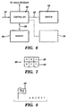
- the present invention illustrated in FIG. 6, provides an apparatus for determining the orientation of a digital camera, and, if necessary, for rotationally transforming the captured digital image such that it is displayed in the proper format when processed by an image manipulation program.
- the digital camera orientation apparatus of the present invention includes an orientation switch 32 for determining the orientation of the digital camera, a memory 34 for storing the digital image data 36 captured by the digital camera, and a controller 38 for controlling the storage of the digital image data 36 in the memory 34 according to the output of the orientation switch 32.
- the controller 38 also coordinates the transfer of digital image data from the memory 34 to an image manipulation program operating on a computer.
- the controller 38 can be implemented in any manner known in the art.
- the orientation switch 32 is implemented using a pendulum-type switch which uses gravity to automatically sense the orientation (portrait or landscape) of the digital camera. Switches of this type are disclosed, for example, in U.S. Patent No. 4,183,645, U.S. Patent No. 4,801,793, and U.S. Patent No. 5,541,697, incorporated herein by reference. Of course, other types of switches for determining the orientation of the digital camera can be used without departing from the scope of the present invention.
- a manually actuated switch 70 (or a plurality thereof), disposed on the body of the digital camera, can be used by an operator to manually designate the orientation in which the image data is stored in memory, displayed by an image manipulation program on a computer display, or displayed on the built-in (or attachable) LCD display of the camera itself.
- the switch 70 can be used in lieu of, or in combination with, the orientation switch 32.
- the controller 38 stores the digital image data 36 corresponding thereto in the memory 34 in a conventional manner.
- the controller 38 stores the digital data in such a way that its original orientation is maintained when accessed by an image manipulation program, without the manual post-processing rotation step required in the prior art.
- a simple example will illustrate the storage of the digital image data 36 in the memory 34 for a digital image captured in landscape and portrait orientations.
- a digital image captured at a hypothetical resolution of 3x2 pixels is stored in the memory 34 such that the original orientation of the image is maintained.
- the method used in this example can be easily extrapolated for use in the storage of an actual digital image which has a much higher resolution (e.g., 32Ox240 or 64Ox480 pixels).
- storage method disclosed below is only one of many possible methods for the storage of the digital image data 36 in the memory 34. Other storage methods can be used without departing from the scope of the present invention.
- the digital image data 40 for a digital image captured in a landscape orientation at a resolution of 3x2 pixels is displayed by an image manipulation program as illustrated in FIG. 7.
- the data 40 comprises a matrix having a first row 42 including pixel data A, B, and C, and a second row 44 including pixel data D, E, and F.
- the pixel data for a given pixel X typically includes three color components Xr, Xg, and Xb, corresponding to red, green and blue data, respectively.
- the orientation switch 32 When the orientation switch 32 outputs an orientation signal 46 to the controller 38 indicating that the digital image was captured in the landscape orientation, the data 40 is stored in the memory 34 by the controller 38 as shown in FIG. 8.
- a landscape image flag 48 indicates that the image was captured in the landscape orientation at a resolution of 3x2 pixels.
- a block of data including the pixel data A, B, C, D, E, and F follows the landscape image flag 48.
- the landscape image flag 48 is used to separate the pixel data into first and second segments A, B and C, and D, E, and F, respectively, such that it can be displayed as shown in FIG. 7.
- the separation of the pixel data can be performed by the controller 38 or by the image manipulation program upon receipt of the data.
- the digital image data 50 for a digital image captured in a portrait orientation at a resolution of 2x3 pixels is output by a conventional digital camera in the landscape orientation shown in FIG. 9.
- the digital data 50 comprises a 3x2 matrix including a first row 52 including pixel data A, B, and C, and a second row 54 including pixel data D, E, and F.
- the data should be arranged as shown in either FIG. 10 or FIG. 11, depending upon whether the digital camera was rotated clockwise (directional arrow CW) or counterclockwise (directional arrow CCW) from the landscape to a portrait orientation.
- the controller 38 Upon receipt of an orientation signal 46 from the orientation switch 32 indicating that a digital image was captured in a portrait orientation, the controller 38 rotationally transforms the data prior to its storage in the memory 34.
- the orientation signal 46 provides the controller 38 with a first portrait image flag 56, indicating that the digital image was captured in the portrait orientation of FIG. 4, or a second portrait image flag 58, indicating that the digital image was captured in the portrait orientation of FIG. 5.
- the data illustrated in FIG. 10 is stored in the memory 34 as shown in FIG. 12.
- the portrait image flag 56 indicates that the image was captured in the portrait orientation of FIG. 4 at a resolution of 2x3 pixels.
- a block of rotationally transformed data including the pixel data D, A, E, B, F and C follows the portrait image flag 56.
- the controller 38 uses the portrait image flag 56 to separate the pixel data into a first segment D, A, a second segment E, B, and a third segment F, C, such that it can be displayed as shown in FIG. 10. Again, the separation of the pixel data can be performed by the controller 38 or by the image manipulation program upon receipt of the data.
- the rotational transformation of the digital image data corresponding to an image captured in a portrait orientation is performed by the controller 38 prior to the storage of the digital data 36 in the memory 34.
- the controller 38 stores a portrait image flag 56 or 58, and an untransformed block of digital data (pixel data A, B, C, D, E, and F), in the memory 34.
- the rotational transformation is performed by the controller 38 or the image manipulation program after the data is accessed from the memory 34. This process is automatic and does not require any user actuated post processing rotation steps.
- orientation determining system of the present invention can be used to automatically provide and/or display digital data captured by a digital video camera in the correct orientation.
- Such modifications and variations that may be apparent to a person skilled in the art are intended to be included within the scope of this invention as defined by the accompanying claims.
Abstract
Description
the accompanying drawings, wherein like reference numerals refer to like elements
throughout the drawings.
When a digital image is captured in a landscape orientation, the
When a digital image is captured in a portrait orientation, however, the
resolution of 2x3 pixels is output by a conventional digital camera in the landscape orientation shown in FIG. 9. The
In the preferred embodiment of the present invention, the rotational transformation of
the digital image data corresponding to an image captured in a portrait orientation is performed by the
Claims (15)
- An imaging system for capturing a digital image including: an apparatus for determining an orientation (30) of said imaging system during capture of a digital image (36), and for automatically providing said digital image in said determined orientation.
- The imaging system according to claim 1, further including: a display (10) for displaying said digital image (36) in said determined orientation.
- The imaging system according to claim 1, further including: memory (34) for storing said digital image.
- The imaging system according to claim 3, further including: a controller (38) for storing said digital image (36) in said memory (34) in said determined orientation.
- The imaging system according to claim 3, further including: a controller (38) for storing said digital image (36) and an orientation signal (46) identifying the determined orientation of said imaging system in said memory (34), and for outputting said digital image from said memory in said determined orientation based on said orientation signal.
- The imaging system according to claim 5, wherein said orientation signal (46) is provided by an orientation switch (32).
- The imaging system according to claim 6, wherein said orientation switch (32) discriminates between a finite number of possible orientations of said imaging system.
- The imaging system according to claim 6, wherein said orientation switch (32) discriminates between an image captured in a landscape orientation (40) and an image captured in a portrait orientation (50).
- The imaging system according to claim 8, wherein said imaging system is a digital camera (20).
- The imaging system according to claim 1, wherein said imaging system is a digital camera (20).
- A method for use with a digital camera (20), comprising the steps of: determining an orientation (30) of said digital camera during capture of a digital image (36); and, automatically providing said digital image in said determined orientation.
- The method of claim 11, further including the step of : automatically displaying (10) said digital image (36) in said determined orientation.
- The method of claim 11, further including the steps of: capturing said digital image in a landscape orientation (40); and,automatically providing said digital image in said landscape orientation.
- The method of claim 11, further including the steps of: capturing said digital image in a portrait orientation (50); and,automatically providing said digital image in said portrait orientation.
- The method of claim 11, further including the steps of: storing said digital image (36) in memory (34) in a predetermined orientation;
automatically transforming said stored digital image to said determined orientation; and,
providing said digital image in said determined orientation.
Applications Claiming Priority (2)
| Application Number | Priority Date | Filing Date | Title |
|---|---|---|---|
| US77394196A | 1996-12-30 | 1996-12-30 | |
| US773941 | 1996-12-30 |
Publications (2)
| Publication Number | Publication Date |
|---|---|
| EP0851675A2 true EP0851675A2 (en) | 1998-07-01 |
| EP0851675A3 EP0851675A3 (en) | 1999-11-03 |
Family
ID=25099783
Family Applications (1)
| Application Number | Title | Priority Date | Filing Date |
|---|---|---|---|
| EP97204043A Withdrawn EP0851675A3 (en) | 1996-12-30 | 1997-12-19 | Method and apparatus for automatically determining the orientation of a digital camera |
Country Status (2)
| Country | Link |
|---|---|
| EP (1) | EP0851675A3 (en) |
| JP (1) | JPH10210405A (en) |
Cited By (15)
| Publication number | Priority date | Publication date | Assignee | Title |
|---|---|---|---|---|
| EP0998816A1 (en) * | 1997-07-31 | 2000-05-10 | Flashpoint Technology, Inc. | Method and system for auto rotating a display for managing portrait and landscape images in a camera |
| GB2384381A (en) * | 2002-01-17 | 2003-07-23 | James Leigh Taylor | Camera incorporating tilt sensor |
| EP1345422A1 (en) * | 2002-03-14 | 2003-09-17 | Creo IL. Ltd. | A device and a method for determining the orientation of an image capture apparatus |
| US6747690B2 (en) | 2000-07-11 | 2004-06-08 | Phase One A/S | Digital camera with integrated accelerometers |
| DE10261295A1 (en) * | 2002-12-27 | 2004-07-08 | Bernhard Rauscher | Method for detection of position of camera when picture was taken, to be used for later digital processing, comprising position recording sensor |
| EP1513334A1 (en) * | 2003-09-08 | 2005-03-09 | Sony Ericsson Mobile Communications AB | Method of and apparatus for picture orientation |
| FR2862832A1 (en) * | 2003-11-20 | 2005-05-27 | Sagem | Clam shell type telephone for use as digital camera, has upper part with display and lower part with camera, where parts are articulated around hinge that allows lower part to rotate at certain degrees with respect to upper part |
| US6940570B1 (en) | 1998-11-27 | 2005-09-06 | Sharp Kabushiki Kaisha | Lighting element for liquid crystal display |
| FR2874470A1 (en) * | 2004-08-23 | 2006-02-24 | Cit Alcatel | Digital image acquiring apparatus e.g. mobile telephone, for e.g. global system for mobile communication network, has unit to control storage of image data and reoriented image data during actuation of respective buttons |
| WO2006033797A1 (en) * | 2004-09-17 | 2006-03-30 | Matsushita Electric Industrial Co., Ltd. | Method and apparatus for automatic image orientation normalization |
| US7554578B2 (en) | 2000-07-11 | 2009-06-30 | Phase One A/S | Digital camera with integrated accelerometers |
| US20110128410A1 (en) * | 2009-12-01 | 2011-06-02 | Samsung Electronics Co., Ltd. | Apparatus for and method of taking image of mobile terminal |
| US8102457B1 (en) | 1997-07-09 | 2012-01-24 | Flashpoint Technology, Inc. | Method and apparatus for correcting aspect ratio in a camera graphical user interface |
| US8127232B2 (en) | 1998-12-31 | 2012-02-28 | Flashpoint Technology, Inc. | Method and apparatus for editing heterogeneous media objects in a digital imaging device |
| US9224145B1 (en) | 2006-08-30 | 2015-12-29 | Qurio Holdings, Inc. | Venue based digital rights using capture device with digital watermarking capability |
Families Citing this family (1)
| Publication number | Priority date | Publication date | Assignee | Title |
|---|---|---|---|---|
| CN100389589C (en) * | 2003-12-15 | 2008-05-21 | 联想(北京)有限公司 | A method for automatically correcting digital photo display |
Citations (3)
| Publication number | Priority date | Publication date | Assignee | Title |
|---|---|---|---|---|
| US5295077A (en) * | 1991-01-23 | 1994-03-15 | Ricoh Company, Ltd. | Digital electronic still camera |
| EP0738075A2 (en) * | 1995-04-13 | 1996-10-16 | Eastman Kodak Company | Electronic still camera having automatic orientation sensing and image correction |
| US5576759A (en) * | 1992-12-07 | 1996-11-19 | Nikon Corporation | Image processing system for classifying reduced image data |
-
1997
- 1997-12-19 EP EP97204043A patent/EP0851675A3/en not_active Withdrawn
- 1997-12-25 JP JP9367435A patent/JPH10210405A/en active Pending
Patent Citations (3)
| Publication number | Priority date | Publication date | Assignee | Title |
|---|---|---|---|---|
| US5295077A (en) * | 1991-01-23 | 1994-03-15 | Ricoh Company, Ltd. | Digital electronic still camera |
| US5576759A (en) * | 1992-12-07 | 1996-11-19 | Nikon Corporation | Image processing system for classifying reduced image data |
| EP0738075A2 (en) * | 1995-04-13 | 1996-10-16 | Eastman Kodak Company | Electronic still camera having automatic orientation sensing and image correction |
Cited By (24)
| Publication number | Priority date | Publication date | Assignee | Title |
|---|---|---|---|---|
| US8970761B2 (en) | 1997-07-09 | 2015-03-03 | Flashpoint Technology, Inc. | Method and apparatus for correcting aspect ratio in a camera graphical user interface |
| US8102457B1 (en) | 1997-07-09 | 2012-01-24 | Flashpoint Technology, Inc. | Method and apparatus for correcting aspect ratio in a camera graphical user interface |
| EP0998816A4 (en) * | 1997-07-31 | 2000-11-15 | Flashpoint Technology Inc | Method and system for auto rotating a display for managing portrait and landscape images in a camera |
| EP0998816A1 (en) * | 1997-07-31 | 2000-05-10 | Flashpoint Technology, Inc. | Method and system for auto rotating a display for managing portrait and landscape images in a camera |
| US6940570B1 (en) | 1998-11-27 | 2005-09-06 | Sharp Kabushiki Kaisha | Lighting element for liquid crystal display |
| US8972867B1 (en) | 1998-12-31 | 2015-03-03 | Flashpoint Technology, Inc. | Method and apparatus for editing heterogeneous media objects in a digital imaging device |
| US8127232B2 (en) | 1998-12-31 | 2012-02-28 | Flashpoint Technology, Inc. | Method and apparatus for editing heterogeneous media objects in a digital imaging device |
| US8619146B2 (en) | 2000-07-11 | 2013-12-31 | Phase One A/S | Digital camera with integrated accelerometers |
| US8908053B2 (en) | 2000-07-11 | 2014-12-09 | Phase One A/S | Digital camera with integrated accelerometers |
| US8854482B2 (en) | 2000-07-11 | 2014-10-07 | Phase One A/S | Digital camera with integrated accelerometers |
| US6747690B2 (en) | 2000-07-11 | 2004-06-08 | Phase One A/S | Digital camera with integrated accelerometers |
| US8189058B2 (en) | 2000-07-11 | 2012-05-29 | Phase One A/S | Digital camera with integrated accelerometers |
| US7554578B2 (en) | 2000-07-11 | 2009-06-30 | Phase One A/S | Digital camera with integrated accelerometers |
| US8102429B2 (en) | 2000-07-11 | 2012-01-24 | Phase One A/S | Digital camera with integrated accelerometers |
| GB2384381A (en) * | 2002-01-17 | 2003-07-23 | James Leigh Taylor | Camera incorporating tilt sensor |
| EP1345422A1 (en) * | 2002-03-14 | 2003-09-17 | Creo IL. Ltd. | A device and a method for determining the orientation of an image capture apparatus |
| DE10261295A1 (en) * | 2002-12-27 | 2004-07-08 | Bernhard Rauscher | Method for detection of position of camera when picture was taken, to be used for later digital processing, comprising position recording sensor |
| EP1513334A1 (en) * | 2003-09-08 | 2005-03-09 | Sony Ericsson Mobile Communications AB | Method of and apparatus for picture orientation |
| FR2862832A1 (en) * | 2003-11-20 | 2005-05-27 | Sagem | Clam shell type telephone for use as digital camera, has upper part with display and lower part with camera, where parts are articulated around hinge that allows lower part to rotate at certain degrees with respect to upper part |
| WO2005053305A1 (en) * | 2003-11-20 | 2005-06-09 | Sagem Sa | Camera-equipped clamshell mobile telephone |
| FR2874470A1 (en) * | 2004-08-23 | 2006-02-24 | Cit Alcatel | Digital image acquiring apparatus e.g. mobile telephone, for e.g. global system for mobile communication network, has unit to control storage of image data and reoriented image data during actuation of respective buttons |
| WO2006033797A1 (en) * | 2004-09-17 | 2006-03-30 | Matsushita Electric Industrial Co., Ltd. | Method and apparatus for automatic image orientation normalization |
| US9224145B1 (en) | 2006-08-30 | 2015-12-29 | Qurio Holdings, Inc. | Venue based digital rights using capture device with digital watermarking capability |
| US20110128410A1 (en) * | 2009-12-01 | 2011-06-02 | Samsung Electronics Co., Ltd. | Apparatus for and method of taking image of mobile terminal |
Also Published As
| Publication number | Publication date |
|---|---|
| JPH10210405A (en) | 1998-08-07 |
| EP0851675A3 (en) | 1999-11-03 |
Similar Documents
| Publication | Publication Date | Title |
|---|---|---|
| US6798924B2 (en) | System and method for displaying an image indicating a positional relation between partially overlapping images | |
| EP0851675A2 (en) | Method and apparatus for automatically determining the orientation of a digital camera | |
| USRE41088E1 (en) | Apparatus and method for rotating the display orientation of a captured image | |
| US7590335B2 (en) | Digital camera, composition correction device, and composition correction method | |
| US7839429B2 (en) | In-camera panorama stitching method and apparatus | |
| CN1854887B (en) | Method and apparatus for forming a panoramic image | |
| US8085333B2 (en) | Digital camera | |
| RU2437169C2 (en) | Device of image display, device of image taking | |
| KR100581680B1 (en) | Image reproducing device and image reproducing method | |
| US20070172151A1 (en) | Method and apparatus for composing a panoramic photograph | |
| EP0327112B1 (en) | Method and apparatus for displaying picture frames of color photograhic films | |
| US5434958A (en) | Method and apparatus for creating special effects on video screen | |
| US7345774B2 (en) | Apparatus and method for adapting image sensor aspect ratio to print aspect ratio in a digital image capture appliance | |
| JP2948974B2 (en) | Imaging system, electronic camera, computer system for controlling electronic camera, and control method thereof | |
| JP3203263B2 (en) | Imaging system, electronic camera and control method thereof | |
| JPH10155111A (en) | Digital camera | |
| JP2007228233A (en) | Photographic device | |
| JPH0730788A (en) | Video camera apparatus | |
| JP3417359B2 (en) | Digital still camera and display method thereof | |
| JP2008131109A (en) | Image pickup device and control method of image pickup device | |
| US20050122414A1 (en) | Digital camera system and method for maximizing television viewing area | |
| JPH08194246A (en) | Composite camera | |
| EP0860987A2 (en) | Method and apparatus for scanning in slides | |
| JPH09289613A (en) | Image conversion method and its device | |
| JP3567046B2 (en) | Image data transfer method and image input device |
Legal Events
| Date | Code | Title | Description |
|---|---|---|---|
| PUAI | Public reference made under article 153(3) epc to a published international application that has entered the european phase |
Free format text: ORIGINAL CODE: 0009012 |
|
| AK | Designated contracting states |
Kind code of ref document: A2 Designated state(s): AT BE CH DE DK ES FI FR GB GR IE IT LI LU MC NL PT SE |
|
| AX | Request for extension of the european patent |
Free format text: AL;LT;LV;RO;SI |
|
| RAP1 | Party data changed (applicant data changed or rights of an application transferred) |
Owner name: AGFA CORPORATION |
|
| RAP1 | Party data changed (applicant data changed or rights of an application transferred) |
Owner name: AGFA CORPORATION |
|
| PUAL | Search report despatched |
Free format text: ORIGINAL CODE: 0009013 |
|
| AK | Designated contracting states |
Kind code of ref document: A3 Designated state(s): AT BE CH DE DK ES FI FR GB GR IE IT LI LU MC NL PT SE |
|
| AX | Request for extension of the european patent |
Free format text: AL;LT;LV;RO;SI |
|
| AKX | Designation fees paid | ||
| REG | Reference to a national code |
Ref country code: DE Ref legal event code: 8566 |
|
| STAA | Information on the status of an ep patent application or granted ep patent |
Free format text: STATUS: THE APPLICATION IS DEEMED TO BE WITHDRAWN |
|
| 18D | Application deemed to be withdrawn |
Effective date: 20000703 |