EP1503276A2 - Graphical user interface for system status alert on videoconference terminal - Google Patents
Graphical user interface for system status alert on videoconference terminal Download PDFInfo
- Publication number
- EP1503276A2 EP1503276A2 EP04018165A EP04018165A EP1503276A2 EP 1503276 A2 EP1503276 A2 EP 1503276A2 EP 04018165 A EP04018165 A EP 04018165A EP 04018165 A EP04018165 A EP 04018165A EP 1503276 A2 EP1503276 A2 EP 1503276A2
- Authority
- EP
- European Patent Office
- Prior art keywords
- subsystem
- subsystems
- status
- videoconference
- recited
- Prior art date
- Legal status (The legal status is an assumption and is not a legal conclusion. Google has not performed a legal analysis and makes no representation as to the accuracy of the status listed.)
- Granted
Links
Images

Classifications
-
- G—PHYSICS
- G06—COMPUTING; CALCULATING OR COUNTING
- G06F—ELECTRIC DIGITAL DATA PROCESSING
- G06F11/00—Error detection; Error correction; Monitoring
- G06F11/30—Monitoring
- G06F11/32—Monitoring with visual or acoustical indication of the functioning of the machine
- G06F11/324—Display of status information
- G06F11/327—Alarm or error message display
-
- G—PHYSICS
- G06—COMPUTING; CALCULATING OR COUNTING
- G06F—ELECTRIC DIGITAL DATA PROCESSING
- G06F11/00—Error detection; Error correction; Monitoring
- G06F11/07—Responding to the occurrence of a fault, e.g. fault tolerance
- G06F11/0703—Error or fault processing not based on redundancy, i.e. by taking additional measures to deal with the error or fault not making use of redundancy in operation, in hardware, or in data representation
- G06F11/0766—Error or fault reporting or storing
- G06F11/0769—Readable error formats, e.g. cross-platform generic formats, human understandable formats
-
- H—ELECTRICITY
- H04—ELECTRIC COMMUNICATION TECHNIQUE
- H04L—TRANSMISSION OF DIGITAL INFORMATION, e.g. TELEGRAPHIC COMMUNICATION
- H04L12/00—Data switching networks
- H04L12/02—Details
- H04L12/16—Arrangements for providing special services to substations
- H04L12/18—Arrangements for providing special services to substations for broadcast or conference, e.g. multicast
- H04L12/1813—Arrangements for providing special services to substations for broadcast or conference, e.g. multicast for computer conferences, e.g. chat rooms
- H04L12/1822—Conducting the conference, e.g. admission, detection, selection or grouping of participants, correlating users to one or more conference sessions, prioritising transmission
-
- H—ELECTRICITY
- H04—ELECTRIC COMMUNICATION TECHNIQUE
- H04N—PICTORIAL COMMUNICATION, e.g. TELEVISION
- H04N7/00—Television systems
- H04N7/14—Systems for two-way working
- H04N7/15—Conference systems
-
- H—ELECTRICITY
- H04—ELECTRIC COMMUNICATION TECHNIQUE
- H04L—TRANSMISSION OF DIGITAL INFORMATION, e.g. TELEGRAPHIC COMMUNICATION
- H04L12/00—Data switching networks
- H04L12/02—Details
- H04L12/16—Arrangements for providing special services to substations
- H04L12/18—Arrangements for providing special services to substations for broadcast or conference, e.g. multicast
- H04L12/1895—Arrangements for providing special services to substations for broadcast or conference, e.g. multicast for short real-time information, e.g. alarms, notifications, alerts, updates
Definitions
- This invention relates to videoconferencing systems. More particularly it relates to Graphical User Interfaces used to control the operation of a video conference terminal.
- Videoconferencing systems are relatively complex. They typically involve a plurality of video signals, audio signals, processors, apparatus and/or software for data compression and decompression, directional microphones, speakers, video display units, feedback-prevention circuits, cameras and connections to telecommunications networks with associated interface devices.
- a problem in the system may require the immediate attention of the user in order for the videoconference to proceed without interruption.
- a system malfunction might be signaled, but the user was required to troubleshoot the problem without specific guidance from the system.
- the number of subsystems typically present in a videoconferencing system leaves the user with a large number of status indicators to check in order to identify a malfunctioning component. The present invention solves this problem.
- an "Alert" tab or button is displayed on the Graphical User Interface (GUI) of a videoconference terminal when a problem occurs in the embedded system. Selecting the tab or button - e.g., with a pointing device - causes the display to switch to a diagnostic page which provides a specific indication of the problem which has occurred.
- the diagnostic page may provide a graphical indication of the status of various subsystems.
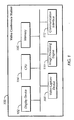
- Figure 1 is a block diagram of a video conference terminal for use in a videoconferencing system.
- Figure 2 is the main page of a graphical user interface for a videoconferencing system with an "Alert" tab displayed.
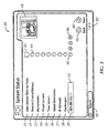
- Figure 3 is the system status page of a graphical user interface for a videoconferencing system showing a disconnected ISDN line.
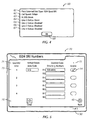
- Figure 4 is a "help" page.
- Figure 5 shows an ISDN configuration page.
- FIG. 1 is a block diagram of an exemplary video conference station 100.
- the video conference station 100 will be described as the local video conference station, although the remote video conference station may contain a similar configuration.
- the video conference station 100 includes a display device 102, a CPU 104, a memory 106, at least one video capture device 108, an image processing engine 110, and a communication interface 112.
- other devices may be provided in the video conference station 100, or not all above-named devices provided.
- the at least one video capture device 108 may be implemented as a charge couple device (CCD) camera, a complementary metal oxide semiconductor (CMOS) camera, or any other type of image capture device.
- CCD charge couple device
- CMOS complementary metal oxide semiconductor
- the at least one video capture device 108 captures images of a user, conference room, or other scenes, and sends the images to the image processing engine 110.
- the image processing engine 110 processes the video image into data packets before the communication interface 112 transmits the data packets to the remote video conference station.
- the image processing engine 110 also transforms received data packets from the remote video conference station into a video signal for display on the display device 102.
- Videoconferencing systems may include an interface for a packet-switched network such as the IP network and/or an interface for a switched network such as the public telephone system. Due to the bandwidth required, a videoconference connection over the telephone system frequently involves one or more ISDN lines. ISDN PRI and ISDN BRI lines differ in the number of channels involved.
- the network interface may comprise a gatekeeper, time server, Global Address Book (GAB) server, and/or a Global management (GM) server.
- GAB Global Address Book
- GM Global management
- a gatekeeper functions as a call manager or multi-point control unit. If an IP connection is lost, all of the foregoing may be lost.
- the type of problem which may cause a system status alert may be a "local problem" - i.e., a problem which prevents the near-end system from communicating with, for example, the ISDN card or the gatekeeper.
- the ALERT tab or button may be displayed on the MAIN screen.
- User selection of the ALERT tab or button with, for example, the local system's remote control, causes the local system to display the SYSTEM STATUS page on the system's display device which may be, for example, a television monitor.
- FIG. 2 depicts an example of the MAIN page 10 of one particular videoconferencing system.
- the page includes data entry area 12 which may be used, for example, to enter the telephone number of a remote videoconferencing unit to be called.
- "Tab" or virtual "button" (hereinafter “tab") 14 may be selected by the user in order to display a telephone directory of remote videoconferencing systems.
- Tab 16 may be selected by the user to display a list of recently-made calls thereby winnowing the number of displayed phone numbers to those frequently used.
- Selection of a tab may be made in any of the ways known in the art for selecting "hot areas" on a video display screen which acts an output device for a processor-based system.
- a pointing device such as a mouse or light pen may be used.
- Touch screens are another suitable input selection means, as are infrared or radio-based remote control devices.
- MAIN screen 10 also includes video window 18 which may display the video signal from either the "near" or "far” end of the videoconference.
- video window 18 contains a footer which displays the user's IP address and ISDN telephone line number.
- Tab 20 is the SYSTEM tab which may be selected by the user to access certain administrative functions. In some embodiments, these administrative functions may be password protected.
- ALERT tab 22 which may appear on MAIN screen 10 when a problem in the embedded system is detected. As shown in the example of Figure 2, ALERT tab 22 is highlighted (by, in the illustrated example, a change in the background color of the tab).
- Selection of ALERT tab 22 by the user causes the display to change to a page which indicates the particular item(s) causing the fault condition.
- the page used for this function is SYSTEM STATUS page 30.
- An example of a SYSTEM STATUS page is illustrated in Figure 3.
- SYSTEM STATUS page Various subsystems may be shown on the SYSTEM STATUS page such as: Auto-Answer Point to Point mode indicator 31; Remote Control Battery 32; Microphones 33; "Visual Concert" subsystem 34 which, in the particular embodiment illustrated, is used for notebook computer and projected displays; Timer Server 35; Global Directories availability 36; IP Network 37; Gatekeeper 38; and, ISDN BRI Slot 1.
- the SYSTEM STATUS page may be available on the World Wide Web if the videoconference is using an IP connection. In this way, a remote diagnosis of a problem may be effected.
- Auto-Answer Point to Point mode 31 has associated indicator 42 which, in the illustrated example, is a rectangular status indicator which is indicative of a mode which does not affect the particular videoconference in progress - i.e., although not active or selected, the mode is not a system fault.
- Subsystems 32 through 38, inclusive, have associated status indicators which are upwardly pointing arrows 44 in the illustrated example.
- An up arrow indicates a fully functional or "normal" state.
- ISDN BRI Slot 1 indicator 39 has four associated downwardly pointing arrows 46 numbered 1 through 4.
- Down arrow 1 has flag color 48 which may be used to indicate a problem or fault on ISDN line number 1 - for example, the line may have been disconnected.
- the standard background color of lines 2 through 4 indicates that no particular problem has been detected, but the down arrow 46 indication may be used to show that these lines have not been selected for use in the particular videoconference being conducted.
- Subsystem indicator 39 is shown with highlight 52 which may be used to indicate selection by the user.
- initial highlighting of a subsystem having a fault condition may be performed by the system.
- the user may defer to the system's selection or may choose to select a different subsystem for further information.
- Activation of the selection may, in some embodiments, be used to access a "help" screen containing more detailed information on the particular subsystem selected.
- An example of a help screen for the ISDN BRI Slot 1 of a particular videoconferencing system is illustrated in Figure 4 as screen 60.
- the display includes: interface identifier 61; data transmission rate indicator 62; protocol status indicator 63; line 1 status indicator 64; line 2 status indicator 65; line 3 status indicator 66; and, line 4 status indicator 67.
- ISDN line 1 is down (63); lines 2,3, and 4 are disabled (64, 65, 66); no communications protocol is detected (63) (inasmuch as the only communications line is down); and the data rate is down to zero (62).
- the user may return to the previous screen by selecting the OK button 68.
- FIG. 5 there is shown a representative example of ISDN line configuration screen 70.
- this screen may be accessed by a CONFIG button or tab (not shown) on the "help" screen.
- the selected country is shown in country selection indicator 71 and the associated country code may be displayed in country code indicator field 72.
- Line 73 contains data entry fields for area codes and telephone numbers.
- line selection indicator 74 which may be toggled by the user.
- an enabled line is indicated with a check mark in the rightmost column on the screen. For the convenience of the user, all data entry fields may be cleared by selecting "clear" button 75.
Abstract
Description
Activation of the selection may, in some embodiments, be used to access a "help" screen containing more detailed information on the particular subsystem selected. An example of a help screen for the
Claims (12)
- A method for alerting the user of a videoconferencing system to a problem in the embedded system during a videoconference comprising:displaying, in response to a detected malfunction, a selectable indicator on the graphical user interface of a videoconference terminal;displaying, in response to user selection of the selectable indicator, a list of subsystems within the videoconference system; and,associating with each displayed subsystem an icon indicative of the status of the subsystem.
- A method as recited in claim 1 wherein an upwardly-pointing arrow is used as an icon indicative of the status of a functioning subsystem.
- A method as recited in claim 1 wherein a downwardly-point arrow is used as an icon indicative of the status of a subsystem selected from the group consisting of malfunctioning subsystems, disconnected subsystems, non-responding subsystems, non-powered subsystems and unused subsystems.
- A method as recited in claim 1 wherein a generally rectangular, geometric shape is used as an icon indicative of the status of a subsystem which is selected from the group consisting of unused subsystems, non-selected subsystems, non-essential subsystems, non-applicable subsystems, inactive subsystems and unnecessary subsystems.
- A method for alerting the user of a videoconferencing system to a problem in the embedded system during a videoconference comprising:displaying, in response to a detected malfunction, a selectable indicator on the graphical user interface of a videoconference terminal;displaying, in response to user selection of the selectable indicator, a list of subsystems within the videoconference system;associating with each displayed subsystem an icon indicative of the status of the subsystem; and,displaying, in response to user selection of a displayed subsystem, additional information concerning the status of the selected subsystem.
- A method as recited in claim 5 wherein the additional information concerning the status of the selected subsystem is textual information.
- A method as recited in claim 5 wherein the additional information concerning the status of the selected subsystem is numeric information.
- A method as recited in claim 5 wherein the additional information concerning the status of the selected subsystem is displayed in graphical form.
- A processor-based videoconference terminal comprising a medium storing instructions for causing the processor to:display, in response to a detected malfunction, a selectable indicator on a graphical user interface of the videoconference terminal;display, in response to user selection of the selectable indicator, a list of subsystems within the videoconference system;associate with each displayed subsystem an icon indicative of the status of the subsystem; and,display, in response to user selection of a displayed subsystem, additional information concerning the status of the selected subsystem.
- A method as recited in claim 1 further comprising
publishing on a website a list of subsystems within the videoconference system together with an icon indicative of the status of each subsystem. - A method as recited in claim 10 further comprising publishing a link to a web page containing additional information concerning a selected subsystem.
- A method as recited in claim 11 wherein the link is a hypertext link.
Applications Claiming Priority (2)
| Application Number | Priority Date | Filing Date | Title |
|---|---|---|---|
| US631668 | 1990-12-20 | ||
| US10/631,668 US20050028106A1 (en) | 2003-07-31 | 2003-07-31 | Graphical user interface for system status alert on videoconference terminal |
Publications (3)
| Publication Number | Publication Date |
|---|---|
| EP1503276A2 true EP1503276A2 (en) | 2005-02-02 |
| EP1503276A3 EP1503276A3 (en) | 2008-07-23 |
| EP1503276B1 EP1503276B1 (en) | 2012-10-17 |
Family
ID=33541527
Family Applications (1)
| Application Number | Title | Priority Date | Filing Date |
|---|---|---|---|
| EP04018165A Not-in-force EP1503276B1 (en) | 2003-07-31 | 2004-07-30 | Graphical user interface for system status alert on videoconference terminal |
Country Status (3)
| Country | Link |
|---|---|
| US (1) | US20050028106A1 (en) |
| EP (1) | EP1503276B1 (en) |
| HK (1) | HK1072297A1 (en) |
Cited By (1)
| Publication number | Priority date | Publication date | Assignee | Title |
|---|---|---|---|---|
| CN100456233C (en) * | 2005-10-09 | 2009-01-28 | 光宝科技股份有限公司 | Method and system for displaying graphic user interface of application program |
Families Citing this family (9)
| Publication number | Priority date | Publication date | Assignee | Title |
|---|---|---|---|---|
| BRPI0822250A2 (en) * | 2008-04-30 | 2019-04-09 | Hewlett Packard Development Co | event management system, event management method and program product |
| US20110069141A1 (en) * | 2008-04-30 | 2011-03-24 | Mitchell April S | Communication Between Scheduled And In Progress Event Attendees |
| WO2010036261A1 (en) * | 2008-09-26 | 2010-04-01 | Hewlett-Packard Development Company, L.P. | Event management system for creating a second event |
| US20100091687A1 (en) * | 2008-10-15 | 2010-04-15 | Ted Beers | Status of events |
| US7792901B2 (en) * | 2008-10-15 | 2010-09-07 | Hewlett-Packard Development Company, L.P. | Reconfiguring a collaboration event |
| US8427522B2 (en) * | 2009-12-23 | 2013-04-23 | Lifesize Communications, Inc. | Remotely monitoring and troubleshooting a videoconference |
| US8312055B2 (en) * | 2010-06-11 | 2012-11-13 | Sony Corporation | Content alert upon availability for internet-enabled TV |
| US9552330B2 (en) | 2012-03-23 | 2017-01-24 | International Business Machines Corporation | Indicating a page number of an active document page within a document |
| US10237546B2 (en) * | 2016-04-05 | 2019-03-19 | Gbh Communications, Inc. | Videoconference equipment monitoring system |
Citations (1)
| Publication number | Priority date | Publication date | Assignee | Title |
|---|---|---|---|---|
| US6138150A (en) * | 1997-09-03 | 2000-10-24 | International Business Machines Corporation | Method for remotely controlling computer resources via the internet with a web browser |
Family Cites Families (7)
| Publication number | Priority date | Publication date | Assignee | Title |
|---|---|---|---|---|
| US6728784B1 (en) * | 1996-08-21 | 2004-04-27 | Netspeak Corporation | Collaborative multimedia architecture for packet-switched data networks |
| US6145098A (en) * | 1997-05-13 | 2000-11-07 | Micron Electronics, Inc. | System for displaying system status |
| US6662220B1 (en) * | 1999-04-30 | 2003-12-09 | Hewlett-Packard Development Company, L.P. | Method and apparatus for remote computer management using web browser and hyper-media managed object applications |
| US20020147777A1 (en) * | 2001-02-06 | 2002-10-10 | Hackbarth Randy L. | Apparatus and method for use in portal service for a team utilizing collaboration services |
| US6810496B1 (en) * | 2001-11-07 | 2004-10-26 | Ciena Corporation | System and method for troubleshooting a network |
| US20050083851A1 (en) * | 2002-11-18 | 2005-04-21 | Fotsch Donald J. | Display of a connection speed of an on-line user |
| US7139379B2 (en) * | 2003-06-19 | 2006-11-21 | International Business Machines Corporation | Monitoring telephone conferences through a network of computer controlled display terminals, each associated with a telephone station and displaying a user-interactive monitoring page |
-
2003
- 2003-07-31 US US10/631,668 patent/US20050028106A1/en not_active Abandoned
-
2004
- 2004-07-30 EP EP04018165A patent/EP1503276B1/en not_active Not-in-force
-
2005
- 2005-03-08 HK HK05102031.2A patent/HK1072297A1/en not_active IP Right Cessation
Patent Citations (1)
| Publication number | Priority date | Publication date | Assignee | Title |
|---|---|---|---|---|
| US6138150A (en) * | 1997-09-03 | 2000-10-24 | International Business Machines Corporation | Method for remotely controlling computer resources via the internet with a web browser |
Cited By (1)
| Publication number | Priority date | Publication date | Assignee | Title |
|---|---|---|---|---|
| CN100456233C (en) * | 2005-10-09 | 2009-01-28 | 光宝科技股份有限公司 | Method and system for displaying graphic user interface of application program |
Also Published As
| Publication number | Publication date |
|---|---|
| US20050028106A1 (en) | 2005-02-03 |
| EP1503276B1 (en) | 2012-10-17 |
| EP1503276A3 (en) | 2008-07-23 |
| HK1072297A1 (en) | 2005-08-19 |
Similar Documents
| Publication | Publication Date | Title |
|---|---|---|
| CN111917988B (en) | Remote camera application method, system and medium of cloud mobile phone | |
| US9473741B2 (en) | Teleconference system and teleconference terminal | |
| US6414707B1 (en) | Apparatus and method for incorporating virtual video conferencing environments | |
| EP3002905B1 (en) | Unified communication-based video conference call method, device and system | |
| US20030142215A1 (en) | Network configuration file for automatically transmitting images from an electronic still camera | |
| EP0837605A2 (en) | Camera control system | |
| US20080122920A1 (en) | Web server and method for monitoring system | |
| US20060233192A1 (en) | Display control method and information processing apparatus | |
| CN113329240A (en) | Screen projection method and device | |
| CN104427293A (en) | Method and device for establishing video conference interface and video terminal | |
| EP1503276A2 (en) | Graphical user interface for system status alert on videoconference terminal | |
| WO2002099582A2 (en) | System and method for point to point integration of personal computers with videoconferencing systems | |
| CN113179208B (en) | Interaction method, interaction device and storage medium | |
| KR101137348B1 (en) | A mobile phone having a visual telecommunication and a visual data processing method therof | |
| CN113139123A (en) | Resource recommendation method, device, server and storage medium | |
| US11310430B2 (en) | Method and apparatus for providing video in portable terminal | |
| CN111400549B (en) | User portrait processing method and system | |
| CN114650442A (en) | Method and device for mirror image screen projection and mirror image screen projection equipment | |
| JPH1169341A (en) | Camera control system, computer terminal, control method of the system and terminal, and storage medium storing the control execution program | |
| JP4551813B2 (en) | Computer and program | |
| KR200434040Y1 (en) | Integrated Surveillance System | |
| JP2002112249A (en) | Monitoring notice method and system, and computer- readable information recording medium with monitoring notice program recorded thereon | |
| TWI253851B (en) | Method for displaying remote images | |
| JP6955067B1 (en) | Display control device, display control method and display control program | |
| JP2002034009A (en) | Bidirectional recognition system and method and recording medium |
Legal Events
| Date | Code | Title | Description |
|---|---|---|---|
| PUAI | Public reference made under article 153(3) epc to a published international application that has entered the european phase |
Free format text: ORIGINAL CODE: 0009012 |
|
| AK | Designated contracting states |
Kind code of ref document: A2 Designated state(s): AT BE BG CH CY CZ DE DK EE ES FI FR GB GR HU IE IT LI LU MC NL PL PT RO SE SI SK TR |
|
| AX | Request for extension of the european patent |
Extension state: AL HR LT LV MK |
|
| REG | Reference to a national code |
Ref country code: HK Ref legal event code: DE Ref document number: 1072297 Country of ref document: HK |
|
| PUAL | Search report despatched |
Free format text: ORIGINAL CODE: 0009013 |
|
| AK | Designated contracting states |
Kind code of ref document: A3 Designated state(s): AT BE BG CH CY CZ DE DK EE ES FI FR GB GR HU IE IT LI LU MC NL PL PT RO SE SI SK TR |
|
| AX | Request for extension of the european patent |
Extension state: AL HR LT LV MK |
|
| 17P | Request for examination filed |
Effective date: 20081113 |
|
| AKX | Designation fees paid |
Designated state(s): AT BE BG CH CY CZ DE DK EE ES FI FR GB GR HU IE IT LI LU MC NL PL PT RO SE SI SK TR |
|
| 17Q | First examination report despatched |
Effective date: 20110513 |
|
| GRAP | Despatch of communication of intention to grant a patent |
Free format text: ORIGINAL CODE: EPIDOSNIGR1 |
|
| GRAS | Grant fee paid |
Free format text: ORIGINAL CODE: EPIDOSNIGR3 |
|
| GRAA | (expected) grant |
Free format text: ORIGINAL CODE: 0009210 |
|
| AK | Designated contracting states |
Kind code of ref document: B1 Designated state(s): AT BE BG CH CY CZ DE DK EE ES FI FR GB GR HU IE IT LI LU MC NL PL PT RO SE SI SK TR |
|
| REG | Reference to a national code |
Ref country code: GB Ref legal event code: FG4D |
|
| REG | Reference to a national code |
Ref country code: CH Ref legal event code: EP |
|
| REG | Reference to a national code |
Ref country code: IE Ref legal event code: FG4D |
|
| REG | Reference to a national code |
Ref country code: AT Ref legal event code: REF Ref document number: 580164 Country of ref document: AT Kind code of ref document: T Effective date: 20121115 |
|
| REG | Reference to a national code |
Ref country code: DE Ref legal event code: R096 Ref document number: 602004039668 Country of ref document: DE Effective date: 20121213 |
|
| REG | Reference to a national code |
Ref country code: HK Ref legal event code: GR Ref document number: 1072297 Country of ref document: HK |
|
| REG | Reference to a national code |
Ref country code: NL Ref legal event code: T3 |
|
| REG | Reference to a national code |
Ref country code: AT Ref legal event code: MK05 Ref document number: 580164 Country of ref document: AT Kind code of ref document: T Effective date: 20121017 |
|
| PG25 | Lapsed in a contracting state [announced via postgrant information from national office to epo] |
Ref country code: FI Free format text: LAPSE BECAUSE OF FAILURE TO SUBMIT A TRANSLATION OF THE DESCRIPTION OR TO PAY THE FEE WITHIN THE PRESCRIBED TIME-LIMIT Effective date: 20121017 Ref country code: ES Free format text: LAPSE BECAUSE OF FAILURE TO SUBMIT A TRANSLATION OF THE DESCRIPTION OR TO PAY THE FEE WITHIN THE PRESCRIBED TIME-LIMIT Effective date: 20130128 Ref country code: SE Free format text: LAPSE BECAUSE OF FAILURE TO SUBMIT A TRANSLATION OF THE DESCRIPTION OR TO PAY THE FEE WITHIN THE PRESCRIBED TIME-LIMIT Effective date: 20121017 |
|
| PG25 | Lapsed in a contracting state [announced via postgrant information from national office to epo] |
Ref country code: PL Free format text: LAPSE BECAUSE OF FAILURE TO SUBMIT A TRANSLATION OF THE DESCRIPTION OR TO PAY THE FEE WITHIN THE PRESCRIBED TIME-LIMIT Effective date: 20121017 Ref country code: SI Free format text: LAPSE BECAUSE OF FAILURE TO SUBMIT A TRANSLATION OF THE DESCRIPTION OR TO PAY THE FEE WITHIN THE PRESCRIBED TIME-LIMIT Effective date: 20121017 Ref country code: CY Free format text: LAPSE BECAUSE OF FAILURE TO SUBMIT A TRANSLATION OF THE DESCRIPTION OR TO PAY THE FEE WITHIN THE PRESCRIBED TIME-LIMIT Effective date: 20121017 Ref country code: PT Free format text: LAPSE BECAUSE OF FAILURE TO SUBMIT A TRANSLATION OF THE DESCRIPTION OR TO PAY THE FEE WITHIN THE PRESCRIBED TIME-LIMIT Effective date: 20130218 Ref country code: GR Free format text: LAPSE BECAUSE OF FAILURE TO SUBMIT A TRANSLATION OF THE DESCRIPTION OR TO PAY THE FEE WITHIN THE PRESCRIBED TIME-LIMIT Effective date: 20130118 Ref country code: BE Free format text: LAPSE BECAUSE OF FAILURE TO SUBMIT A TRANSLATION OF THE DESCRIPTION OR TO PAY THE FEE WITHIN THE PRESCRIBED TIME-LIMIT Effective date: 20121017 |
|
| PG25 | Lapsed in a contracting state [announced via postgrant information from national office to epo] |
Ref country code: AT Free format text: LAPSE BECAUSE OF FAILURE TO SUBMIT A TRANSLATION OF THE DESCRIPTION OR TO PAY THE FEE WITHIN THE PRESCRIBED TIME-LIMIT Effective date: 20121017 |
|
| PG25 | Lapsed in a contracting state [announced via postgrant information from national office to epo] |
Ref country code: SK Free format text: LAPSE BECAUSE OF FAILURE TO SUBMIT A TRANSLATION OF THE DESCRIPTION OR TO PAY THE FEE WITHIN THE PRESCRIBED TIME-LIMIT Effective date: 20121017 Ref country code: DK Free format text: LAPSE BECAUSE OF FAILURE TO SUBMIT A TRANSLATION OF THE DESCRIPTION OR TO PAY THE FEE WITHIN THE PRESCRIBED TIME-LIMIT Effective date: 20121017 Ref country code: CZ Free format text: LAPSE BECAUSE OF FAILURE TO SUBMIT A TRANSLATION OF THE DESCRIPTION OR TO PAY THE FEE WITHIN THE PRESCRIBED TIME-LIMIT Effective date: 20121017 Ref country code: BG Free format text: LAPSE BECAUSE OF FAILURE TO SUBMIT A TRANSLATION OF THE DESCRIPTION OR TO PAY THE FEE WITHIN THE PRESCRIBED TIME-LIMIT Effective date: 20130117 Ref country code: EE Free format text: LAPSE BECAUSE OF FAILURE TO SUBMIT A TRANSLATION OF THE DESCRIPTION OR TO PAY THE FEE WITHIN THE PRESCRIBED TIME-LIMIT Effective date: 20121017 |
|
| REG | Reference to a national code |
Ref country code: DE Ref legal event code: R082 Ref document number: 602004039668 Country of ref document: DE Representative=s name: KAHLER, KAECK & MOLLEKOPF, DE |
|
| RAP2 | Party data changed (patent owner data changed or rights of a patent transferred) |
Owner name: POLYCOM, INC. |
|
| PLBE | No opposition filed within time limit |
Free format text: ORIGINAL CODE: 0009261 |
|
| STAA | Information on the status of an ep patent application or granted ep patent |
Free format text: STATUS: NO OPPOSITION FILED WITHIN TIME LIMIT |
|
| PG25 | Lapsed in a contracting state [announced via postgrant information from national office to epo] |
Ref country code: IT Free format text: LAPSE BECAUSE OF FAILURE TO SUBMIT A TRANSLATION OF THE DESCRIPTION OR TO PAY THE FEE WITHIN THE PRESCRIBED TIME-LIMIT Effective date: 20121017 Ref country code: RO Free format text: LAPSE BECAUSE OF FAILURE TO SUBMIT A TRANSLATION OF THE DESCRIPTION OR TO PAY THE FEE WITHIN THE PRESCRIBED TIME-LIMIT Effective date: 20121017 |
|
| 26N | No opposition filed |
Effective date: 20130718 |
|
| REG | Reference to a national code |
Ref country code: DE Ref legal event code: R081 Ref document number: 602004039668 Country of ref document: DE Owner name: POLYCOM, INC., US Free format text: FORMER OWNER: POLYCOM, INC., PLEASANTON, US Effective date: 20121017 Ref country code: DE Ref legal event code: R081 Ref document number: 602004039668 Country of ref document: DE Owner name: POLYCOM, INC., US Free format text: FORMER OWNER: POLYCOM, INC., PLEASANTON, US Effective date: 20130820 Ref country code: DE Ref legal event code: R082 Ref document number: 602004039668 Country of ref document: DE Representative=s name: KAHLER, KAECK & MOLLEKOPF, DE Effective date: 20130820 Ref country code: DE Ref legal event code: R081 Ref document number: 602004039668 Country of ref document: DE Owner name: POLYCOM, INC., SAN JOSE, US Free format text: FORMER OWNER: POLYCOM, INC., PLEASANTON, CALIF., US Effective date: 20121017 Ref country code: DE Ref legal event code: R081 Ref document number: 602004039668 Country of ref document: DE Owner name: POLYCOM, INC., SAN JOSE, US Free format text: FORMER OWNER: POLYCOM, INC., PLEASANTON, CALIF., US Effective date: 20130820 Ref country code: DE Ref legal event code: R082 Ref document number: 602004039668 Country of ref document: DE Representative=s name: KAHLER KAECK MOLLEKOPF PARTNERSCHAFT VON PATEN, DE Effective date: 20130820 |
|
| REG | Reference to a national code |
Ref country code: DE Ref legal event code: R097 Ref document number: 602004039668 Country of ref document: DE Effective date: 20130718 |
|
| PG25 | Lapsed in a contracting state [announced via postgrant information from national office to epo] |
Ref country code: MC Free format text: LAPSE BECAUSE OF FAILURE TO SUBMIT A TRANSLATION OF THE DESCRIPTION OR TO PAY THE FEE WITHIN THE PRESCRIBED TIME-LIMIT Effective date: 20121017 |
|
| REG | Reference to a national code |
Ref country code: CH Ref legal event code: PL |
|
| REG | Reference to a national code |
Ref country code: IE Ref legal event code: MM4A |
|
| REG | Reference to a national code |
Ref country code: FR Ref legal event code: ST Effective date: 20140331 |
|
| PG25 | Lapsed in a contracting state [announced via postgrant information from national office to epo] |
Ref country code: LI Free format text: LAPSE BECAUSE OF NON-PAYMENT OF DUE FEES Effective date: 20130731 Ref country code: CH Free format text: LAPSE BECAUSE OF NON-PAYMENT OF DUE FEES Effective date: 20130731 |
|
| PG25 | Lapsed in a contracting state [announced via postgrant information from national office to epo] |
Ref country code: FR Free format text: LAPSE BECAUSE OF NON-PAYMENT OF DUE FEES Effective date: 20130731 |
|
| PG25 | Lapsed in a contracting state [announced via postgrant information from national office to epo] |
Ref country code: IE Free format text: LAPSE BECAUSE OF NON-PAYMENT OF DUE FEES Effective date: 20130730 |
|
| PGFP | Annual fee paid to national office [announced via postgrant information from national office to epo] |
Ref country code: GB Payment date: 20140624 Year of fee payment: 11 |
|
| PGFP | Annual fee paid to national office [announced via postgrant information from national office to epo] |
Ref country code: NL Payment date: 20140630 Year of fee payment: 11 Ref country code: DE Payment date: 20140630 Year of fee payment: 11 |
|
| PG25 | Lapsed in a contracting state [announced via postgrant information from national office to epo] |
Ref country code: TR Free format text: LAPSE BECAUSE OF FAILURE TO SUBMIT A TRANSLATION OF THE DESCRIPTION OR TO PAY THE FEE WITHIN THE PRESCRIBED TIME-LIMIT Effective date: 20121017 |
|
| PG25 | Lapsed in a contracting state [announced via postgrant information from national office to epo] |
Ref country code: HU Free format text: LAPSE BECAUSE OF FAILURE TO SUBMIT A TRANSLATION OF THE DESCRIPTION OR TO PAY THE FEE WITHIN THE PRESCRIBED TIME-LIMIT; INVALID AB INITIO Effective date: 20040730 Ref country code: LU Free format text: LAPSE BECAUSE OF NON-PAYMENT OF DUE FEES Effective date: 20130730 |
|
| REG | Reference to a national code |
Ref country code: DE Ref legal event code: R119 Ref document number: 602004039668 Country of ref document: DE |
|
| GBPC | Gb: european patent ceased through non-payment of renewal fee |
Effective date: 20150730 |
|
| REG | Reference to a national code |
Ref country code: NL Ref legal event code: MM Effective date: 20150801 |
|
| PG25 | Lapsed in a contracting state [announced via postgrant information from national office to epo] |
Ref country code: DE Free format text: LAPSE BECAUSE OF NON-PAYMENT OF DUE FEES Effective date: 20160202 Ref country code: GB Free format text: LAPSE BECAUSE OF NON-PAYMENT OF DUE FEES Effective date: 20150730 |
|
| PG25 | Lapsed in a contracting state [announced via postgrant information from national office to epo] |
Ref country code: NL Free format text: LAPSE BECAUSE OF NON-PAYMENT OF DUE FEES Effective date: 20150801 |