US20040123230A1 - Simplified message-passing decoder for low-density parity-check codes - Google Patents
Simplified message-passing decoder for low-density parity-check codes Download PDFInfo
- Publication number
- US20040123230A1 US20040123230A1 US10/696,897 US69689703A US2004123230A1 US 20040123230 A1 US20040123230 A1 US 20040123230A1 US 69689703 A US69689703 A US 69689703A US 2004123230 A1 US2004123230 A1 US 2004123230A1
- Authority
- US
- United States
- Prior art keywords
- message
- bit
- input
- parity
- slope
- Prior art date
- Legal status (The legal status is an assumption and is not a legal conclusion. Google has not performed a legal analysis and makes no representation as to the accuracy of the status listed.)
- Granted
Links
Images


Classifications
-
- H—ELECTRICITY
- H03—ELECTRONIC CIRCUITRY
- H03M—CODING; DECODING; CODE CONVERSION IN GENERAL
- H03M13/00—Coding, decoding or code conversion, for error detection or error correction; Coding theory basic assumptions; Coding bounds; Error probability evaluation methods; Channel models; Simulation or testing of codes
- H03M13/03—Error detection or forward error correction by redundancy in data representation, i.e. code words containing more digits than the source words
- H03M13/05—Error detection or forward error correction by redundancy in data representation, i.e. code words containing more digits than the source words using block codes, i.e. a predetermined number of check bits joined to a predetermined number of information bits
- H03M13/11—Error detection or forward error correction by redundancy in data representation, i.e. code words containing more digits than the source words using block codes, i.e. a predetermined number of check bits joined to a predetermined number of information bits using multiple parity bits
-
- H—ELECTRICITY
- H04—ELECTRIC COMMUNICATION TECHNIQUE
- H04L—TRANSMISSION OF DIGITAL INFORMATION, e.g. TELEGRAPHIC COMMUNICATION
- H04L1/00—Arrangements for detecting or preventing errors in the information received
- H04L1/004—Arrangements for detecting or preventing errors in the information received by using forward error control
- H04L1/0056—Systems characterized by the type of code used
- H04L1/0057—Block codes
-
- H—ELECTRICITY
- H03—ELECTRONIC CIRCUITRY
- H03M—CODING; DECODING; CODE CONVERSION IN GENERAL
- H03M13/00—Coding, decoding or code conversion, for error detection or error correction; Coding theory basic assumptions; Coding bounds; Error probability evaluation methods; Channel models; Simulation or testing of codes
- H03M13/03—Error detection or forward error correction by redundancy in data representation, i.e. code words containing more digits than the source words
- H03M13/05—Error detection or forward error correction by redundancy in data representation, i.e. code words containing more digits than the source words using block codes, i.e. a predetermined number of check bits joined to a predetermined number of information bits
- H03M13/11—Error detection or forward error correction by redundancy in data representation, i.e. code words containing more digits than the source words using block codes, i.e. a predetermined number of check bits joined to a predetermined number of information bits using multiple parity bits
- H03M13/1102—Codes on graphs and decoding on graphs, e.g. low-density parity check [LDPC] codes
- H03M13/1105—Decoding
- H03M13/1111—Soft-decision decoding, e.g. by means of message passing or belief propagation algorithms
- H03M13/1117—Soft-decision decoding, e.g. by means of message passing or belief propagation algorithms using approximations for check node processing, e.g. an outgoing message is depending on the signs and the minimum over the magnitudes of all incoming messages according to the min-sum rule
-
- H—ELECTRICITY
- H04—ELECTRIC COMMUNICATION TECHNIQUE
- H04L—TRANSMISSION OF DIGITAL INFORMATION, e.g. TELEGRAPHIC COMMUNICATION
- H04L1/00—Arrangements for detecting or preventing errors in the information received
- H04L1/004—Arrangements for detecting or preventing errors in the information received by using forward error control
- H04L1/0045—Arrangements at the receiver end
Definitions
- the present invention relates to a decoding technology for channel codes. More particularly, the present invention relates to a message-passing decoder for LDPC (Low-Density Parity-Check) codes that receives data encoded with LDPC codes on a channel, having a consecutive output values, and decodes the coded data using a message-passing decoding algorithm.
- LDPC Low-Density Parity-Check
- LDPC codes are linear block codes reported by Gallager in 1962, and they are defined as a sparse parity-check matrix of which the elements are mostly “0”. LDPC codes were out of the public's mind for a long time due to expense of implementation, but they were re-discovered by MacKay and Neal in 1995. In 1998, irregular LDPC codes derived from generalization of the LDPC codes proposed by Gallager were announced. At the time of the first announcement of the LDPC codes by Gallager, the probabilistic coding method for LDPC codes was also made known, through which method the excellent performance of LDPC codes was demonstrated. It was also found that LDPC codes have an improved performance when they are expanded from binary codes to nonbinary codes.
- LDPC codes Like Turbo codes, LDPC codes have a bit error rate (BER) approaching the channel capacity limit defined by Shannon.
- BER bit error rate
- the irregular LDPC codes known to have the greatest performance are suitable for applications requiring a high-quality transmission environment having a considerably low BER, because they need no more than 0.13 dB in addition to the channel capacitor by Shannon in order to achieve a BER of 10 ⁇ 6 when the block size is about 10 6 bits in the additive white Gaussian noise (AWGN) channel environment.
- AWGN additive white Gaussian noise
- the basic decoding method for LDPC codes includes a probabilistic decoding algorithm, unlike the algebraic decoding algorithm that is the decoding method of the conventional block codes, and adapts a belief propagation method based on graph theory and probabilistic prediction theory. Accordingly, the LDPC decoder calculates, for individual bits of the code word received through the channel, the probability of the corresponding bit being “1” or “0”. The probabilistic information calculated by the decoder is specifically called a “message”, and is used in checking whether or not each parity defined in a parity-check matrix is satisfied.
- the message calculated when a specific parity of the parity-check matrix is satisfied i.e., when the result of the parity check is “0”, is specifically called a “parity-check message”, which specifies the value of each bit of the code word.
- the parity-check message for each parity is used in determining the value of the corresponding bit.
- the information about the bit calculated is called a “bit message”. In the procedure of repeating the message-passing operation, information about the bits of each code word is constantly improved until all the parities of the parity-check matrix are satisfied. If the parities of the parity-check matrix are all satisfied, the decoding of the code word is ended.
- This LLR message decoding method involves a logarithm function operation in message calculation, and it causes a problem in regard to implementation of a nonlinear function.
- a specific value is stored in a read-only memory (ROM) and the output value of an address related to the input is read out from the ROM.
- ROM read-only memory
- the use of this method requires memories of a large capacity and increases the area cost of the integrated circuit, thereby raising the cost of implementation. But, reducing the number of bits representing input and output deteriorates the accuracy of the message calculation to reduce the entire decoding performance and increase the BER.
- the parity-check function used for the calculation of the parity-check message is a monotonically decreasing function that shows a similar decreasing tendency to an exponential function, so the interval can be determined in the manner of the exponential function to drastically reduce approximation errors caused by linear approximation.
- the slope for each interval and the function value at the interval boundary are necessary.
- a simple multiplier is constructed with a combination of summators and shifters. Accordingly, the entire parity-check function can be calculated only with the operations of summators and shifters.
- the present invention proposes a decoder that implements the parity-check function in a simply way.
- FIG. 1 is an illustration of a sparse parity-check matrix constituting one LDPC code
- FIG. 2 is a Tanner graph representing FIG. 1;
- FIG. 3 is an illustration of an encoder and a decoder for LDPC codes
- FIG. 4 is an illustration of a method for calculating a message in each node
- FIG. 5 shows a linearization method of a message-passing function
- FIG. 6 shows a parallel implementation structure of a message calculator for calculating the linearized message-passing function as proposed in the present invention
- FIG. 7 shows an implementation structure of the minimum cost of the message calculator for calculating the linarized message-passing function as proposed in the present invention
- FIG. 8 shows a circuit implementing a multiplier for multiplication of a slope
- FIG. 9 shows a circuit implementing a summator for summating the boundary values of the respective intervals.
- the present invention can be applied to decoding of block codes encoded using LDPC codes.
- the block codes are encoded by way of a sparse parity-check matrix 100 designed to have the least number of elements 110 other than “0” 120 , and a related generator matrix.
- the coding method is exactly the same as the coding of general block codes.
- a Tanner graph 220 is defined from the sparse parity-check matrix 100 , and the message-passing algorithm is applied to the corresponding graph.
- FIG. 2 shows the Tanner graph for the parity-check matrix of FIG. 1.
- the Tanner graph 200 comprises nodes 210 and 220 , and a branch 230 .
- the nodes are divided into parity-check nodes 210 for a parity-check message, and bit nodes 220 for a bit message.
- the number of parity-check nodes 210 is equal to that of columns in the parity-check matrix 100 .
- the number of bit nodes 220 is equal to that of rows in the parity-check matrix 100 .
- the nodes represent the rows and columns of the matrix in sequence.
- the branch 230 contains elements having a non-zero value in the parity-check matrix 100 .
- the leftmost branch of FIG. 2 connecting the first parity-check node to the first bit node represents the element (1,1) of the parity-check matrix.
- the branch connecting the first bit node to the fourth parity-check node represents the element (4,1) of the party-check matrix.
- the coding and decoding process is performed using the above-defined Tanner graph 200 .
- FIG. 3 shows a coder 320 and a decoder 340 .
- the decoder 340 comprises an LLR calculator 341 , a bit node function unit 342 , a check node function unit 344 , and a parity checker 343 .
- ⁇ 2 represents the noise power of the channel.
- the noise power of the channel is given as an externally input parameter.
- the message of each node can be determined using the initial LLR value.
- the calculation method for the message of bit nodes and parity-check nodes is illustrated in FIG. 4.
- a bit node message 414 is calculated using the initial LLR value given by the equation 1.
- the bit node function unit 342 calculates the LLR q ij of the message 414 of bit node 413 corresponding to the j-th parity of the i-th bit according to the following equation 2.
- the parity-check message derived from the equation 3 is transferred to the bit node function unit 342 .
- the bit node function unit 342 calculates the bit message using the updated parity-check message and the initial bit message, and transfers a new bit message to the check node function unit. This operation is repeated a predetermined number of times to obtain the final parity-check message.
- the bit node function unit 342 calculates the LLR of the information bit of each code word through the final parity-check message according to the following equation 5. The value of the corresponding bit is then determined from the LLR.
- a new code word is constructed using the bit values and is fed into the parity checker 343 .
- the parity checker 343 calculates a syndrome for the code word to perform a parity check. With a non-zero syndrome for the code word, the parity checker 343 determines that the decoding of the code word is a failure. If the parity check is successful, the information bit part is extracted from the code word and transferred.
- the respective message calculators 341 , 342 , and 344 have to receive soft decision inputs.
- the LLR calculator 341 receives a soft decision input and calculates the LLR of the soft decision output.
- the output of the LLR calculator 341 is a soft decision output, so the bit node function unit 342 needs a summator for summating soft decision inputs according to the equations 2 and 5.
- the output of the bit node function unit is also a soft decision output, so the check node function unit 344 must receive a soft decision input and the function of the equation 4 receives the soft decision input and generates a soft decision output.
- the equation 4 which is not a linear function, cannot be implemented with the basic calculation blocks in hardware.
- the function of the equation 4 can employ a ROM that receives as many inputs as the number of bits representing the soft decision input and generates as many outputs as the number of bits representing the soft decision output. Accordingly, the implementation cost of the check node function unit is greatly dependent upon the size of the ROM that is determined by the resolution of representing soft decision input and soft decision output.
- the present invention proposes a check node function unit not using the ROM.
- the function of the equation 4 is implemented with basic calculation blocks.
- the basic calculation blocks include multipliers and summators.
- the multipliers are considerably high in price relative to the summators, and not preferably used in the present invention.
- powers of n for the soft decision input cannot be used, and only the linear function can be implemented.
- the function of the equation 4 is divided into intervals, and the value of the linear approximation function for each interval is then calculated to determine the check node function unit 424 .
- the inverse function of the equation 4 is necessary for the calculation of the check node function unit 424 .
- the inverse function of the equation 4 is the same as the equation 4, so the input of the calculator of the equation 4 must be equal in the number of bits to the output.
- the present invention proposes an interval division method as illustrated in FIG. 5 for the linear approximation of the equation 4.
- the actual function 510 of the equation 4 defines only the positive values because it has an absolute value as an input. So, the function 510 of the equation 4 is a monotonically decreasing function that decreases with the same slope of the exponential function.
- the interval for the linear approximation I i is divided as expressed in the following equation 6 so as to have an exponential size.
- n 1 is the length of a word expressing the input value, i.e., the word length
- n 2 is the bit corresponding to the minimum resolution of decimal places expressing the input value.
- the minimum resolution that can be expressed by n 2 is 2 ⁇ n 2.
- slope s i and interval boundary value x i are defined for each interval.
- the slope s is defined as the following equation 8.
- s i ROUND ⁇ ( ⁇ ⁇ ( 2 K + n 1 - i - 1 ) - ⁇ ⁇ ( 2 K + n 1 - i ) 2 K + n 1 - i - 1 - 2 K + n 1 - i , n 2 ) , ⁇ i ⁇ 0 Equation ⁇ ⁇ 8
- the ROUND function of the equation 8 is a function for designating an input as the most approximate one of the binary numbers given by 2 ⁇ n 2 as the minimum resolution.
- the ROUND function is given by the following equation 9.
- ROUND ⁇ ( x , n 2 ) 2 - n 2 ⁇ ⁇ x 2 - n 2 + 1 2 ⁇ Equation ⁇ ⁇ 9
- the boundary value x i is derived from the slope s i and x i ⁇ 1 as in the following equation 10.
- x l ROUND((2 K+n 1 ⁇ 1 ⁇ 2 K+n 1 ⁇ i+1 ) s i +x i ⁇ 1 , n 2 ), i ⁇ 1,
- FIG. 6 illustrates a circuit 600 for calculating the function value of the equation 4 using the slope and the boundary value given by the equations 8 and 10, respectively.
- the soft decision inputs are all positive real values, so an input memory 610 inverts the sign of the negative ( ⁇ ) numbers. Namely, when the value of the most significant bit (MSB) is “1”, the memory value of the input memory 610 is increased by one and the input memory 610 performs a 1's complement operation.
- the value of the input memory 610 is multiplied by the slope s, of each interval at a multiplier 630 , and is added to the interval boundary value generated from a boundary value memory 620 by an adder 640 to determine the function value of the equation 4.
- a multiplexor (MUX) 650 for selecting the on/off state of a switch according to the MSB selects an accurate function value and outputs the selected function value.
- the multiplexor 650 outputs the first calculated value when the bit of the highest order other than 0 in the input memory is the first bit, or the second calculated value when the bit of the highest order other than 0 is the second bit. In this manner, the on/off state of the switch for every bit can be determined.
- the unsolved problem in the above-stated method is the use of multipliers.
- the binary multiplier can be implemented with bit shifters and summators. Namely, for multiplication by 1.5, the input word is shifted to the right side by one bit for multiplication by 0.5 which is then added to itself to result in a binary number, which has a 1.5-fold value of the input word. In the same way, the bits of the input word are shifted to achieve a multiplication by 2.
- the slope is rounded off to a binary number from the equation 8 and the input word is a binary number, so the multiplier can be replaced with a summator and a shifter. Because the number of slopes is limited, summators and shifters are preferably used instead of a general-purpose multiplier in the aspect of curtailment of hardware expenses.
- FIG. 7 shows a circuit 700 derived by simplifying the calculator of FIG. 6 through a curtailment of hardware expenses.
- An input memory 710 has the same function as the input memory 610 of FIG. 6.
- a summator 740 for summating the boundary values also has the same function as the summator 640 of FIG. 6.
- a slope calculator and multiplier 730 calculates a slope used for multiplication from the bit of the highest order other than “0” in the input of the input memory, and multiplies the slope value by way of the shifter and the summator to generate an output 840 .
- a boundary calculator 720 calculates a boundary value 960 from the bit of the highest order other than “0” in the input of the input memory.
- a slope calculator 820 comprises a bit shifter 821 , a ground 822 representing “0”, a word negater 823 , and a switch 824 functioning as a multiplexor.
- Each bit shifter 821 includes all bit shifters necessary for constructing each slope.
- the ground 822 represents a value of “0” usable in the slope calculator.
- the word negater 823 is used for representing the slope.
- the switches 824 combine the result values from the respective shifters to obtain the final result value.
- FIG. 9 shows the boundary calculator 720 of the present invention.
- the boundary calculator 720 comprises a bit shifter 910 , a ground 920 representing “0”, a word negater 930 , and a switch 940 functioning as a multiplexor.
- Each bit shifter 910 includes all bit shifters necessary for constructing each boundary value.
- the ground 920 represents a value of “0” usable in the calculation of the boundary value.
- the word negater 930 is used for representing the boundary value.
- the switches 940 combine the result values from the respective shifters to obtain the final result value.
- the on/off state of the switches is determined from the boundary value corresponding to a selected interval of the input value.
- the hardware resources such as shifters and summators frequently used in the calculation of each boundary value can be reduced.
- the connection state of final summators 830 and 950 is predetermined for the most frequent combination of multiplications of binary values in each boundary value, thereby bringing about the expectation of the curtailment of the resources.
- the present invention rapidly calculates the parity-check message by sharing the resources of the summator and the shifter, relative to the method of implementing a nonlinear function for calculation of the parity-check message with ROMs.
- the use of the summator and the shift as a shared resource reduces the required hardware resources more than with the use of a multiplier.
- the present invention uses the power of 2 as a boundary value of the interval divided for a linear approximation, thereby simplifying the circuits of the slope calculator and the boundary calculator and greatly reducing errors caused by approximation.
- the method of the present invention can be applied to all the monotonic functions and, particularly, exponentially increasing or decreasing nonlinear functions.
Abstract
Description
- This application claims priority to and the benefit of Korea Patent Application No. 2002-83721 filed on Dec. 24, 2002 in the Korean Intellectual Property Office, the content of which is incorporated herein by reference.
- (a) Field of the Invention
- The present invention relates to a decoding technology for channel codes. More particularly, the present invention relates to a message-passing decoder for LDPC (Low-Density Parity-Check) codes that receives data encoded with LDPC codes on a channel, having a consecutive output values, and decodes the coded data using a message-passing decoding algorithm.
- (b) Description of the Related Art
- LDPC codes are linear block codes reported by Gallager in 1962, and they are defined as a sparse parity-check matrix of which the elements are mostly “0”. LDPC codes were out of the public's mind for a long time due to expense of implementation, but they were re-discovered by MacKay and Neal in 1995. In 1998, irregular LDPC codes derived from generalization of the LDPC codes proposed by Gallager were announced. At the time of the first announcement of the LDPC codes by Gallager, the probabilistic coding method for LDPC codes was also made known, through which method the excellent performance of LDPC codes was demonstrated. It was also found that LDPC codes have an improved performance when they are expanded from binary codes to nonbinary codes. Like Turbo codes, LDPC codes have a bit error rate (BER) approaching the channel capacity limit defined by Shannon. The irregular LDPC codes known to have the greatest performance are suitable for applications requiring a high-quality transmission environment having a considerably low BER, because they need no more than 0.13 dB in addition to the channel capacitor by Shannon in order to achieve a BER of 10 −6 when the block size is about 106 bits in the additive white Gaussian noise (AWGN) channel environment.
- The basic decoding method for LDPC codes includes a probabilistic decoding algorithm, unlike the algebraic decoding algorithm that is the decoding method of the conventional block codes, and adapts a belief propagation method based on graph theory and probabilistic prediction theory. Accordingly, the LDPC decoder calculates, for individual bits of the code word received through the channel, the probability of the corresponding bit being “1” or “0”. The probabilistic information calculated by the decoder is specifically called a “message”, and is used in checking whether or not each parity defined in a parity-check matrix is satisfied. The message calculated when a specific parity of the parity-check matrix is satisfied, i.e., when the result of the parity check is “0”, is specifically called a “parity-check message”, which specifies the value of each bit of the code word. The parity-check message for each parity is used in determining the value of the corresponding bit. The information about the bit calculated is called a “bit message”. In the procedure of repeating the message-passing operation, information about the bits of each code word is constantly improved until all the parities of the parity-check matrix are satisfied. If the parities of the parity-check matrix are all satisfied, the decoding of the code word is ended. Typically, systematic codes are used in a channel environment having a low signal-to-noise ratio (SNR), so a specific part of the code word is extracted to reproduce information bits. It is favorable to convert a probabilistic message to a log likelihood ratio (LLR) message for calculation so as to readily achieve message propagation decoding of LDPC binary codes in the AWGN channel environment.
- This LLR message decoding method involves a logarithm function operation in message calculation, and it causes a problem in regard to implementation of a nonlinear function. Typically, in calculation of a nonlinear function for an integrated circuit, a specific value is stored in a read-only memory (ROM) and the output value of an address related to the input is read out from the ROM. The use of this method requires memories of a large capacity and increases the area cost of the integrated circuit, thereby raising the cost of implementation. But, reducing the number of bits representing input and output deteriorates the accuracy of the message calculation to reduce the entire decoding performance and increase the BER.
- It is an advantage of the present invention to implement calculation of a parity-check message in a decoder for LDPC codes by applying a linear approximation method to individual intervals divided from an input interval without using a read-only memory (ROM). The parity-check function used for the calculation of the parity-check message is a monotonically decreasing function that shows a similar decreasing tendency to an exponential function, so the interval can be determined in the manner of the exponential function to drastically reduce approximation errors caused by linear approximation. For the linear approximation, the slope for each interval and the function value at the interval boundary are necessary. A simple multiplier is constructed with a combination of summators and shifters. Accordingly, the entire parity-check function can be calculated only with the operations of summators and shifters. The present invention proposes a decoder that implements the parity-check function in a simply way.
- The accompanying drawings, which are incorporated in and constitute a part of the specification, illustrate an embodiment of the invention, and, together with the description, serve to explain the principles of the invention:
- FIG. 1 is an illustration of a sparse parity-check matrix constituting one LDPC code;
- FIG. 2 is a Tanner graph representing FIG. 1;
- FIG. 3 is an illustration of an encoder and a decoder for LDPC codes;
- FIG. 4 is an illustration of a method for calculating a message in each node;
- FIG. 5 shows a linearization method of a message-passing function;
- FIG. 6 shows a parallel implementation structure of a message calculator for calculating the linearized message-passing function as proposed in the present invention;
- FIG. 7 shows an implementation structure of the minimum cost of the message calculator for calculating the linarized message-passing function as proposed in the present invention;
- FIG. 8 shows a circuit implementing a multiplier for multiplication of a slope; and
- FIG. 9 shows a circuit implementing a summator for summating the boundary values of the respective intervals.
- In the following detailed description, only the preferred embodiment of the invention has been shown and described, simply by way of illustration of the best mode contemplated by the inventor(s) of carrying out the invention. As will be realized, the invention is capable of modification in various obvious respects, all without departing from the invention. Accordingly, the drawings and description are to be regarded as illustrative in nature, and not restrictive.
- The present invention can be applied to decoding of block codes encoded using LDPC codes. The block codes are encoded by way of a sparse parity-
check matrix 100 designed to have the least number ofelements 110 other than “0” 120, and a related generator matrix. The coding method is exactly the same as the coding of general block codes. - In the decoding method of LDPC codes, a
Tanner graph 220 is defined from the sparse parity-check matrix 100, and the message-passing algorithm is applied to the corresponding graph. FIG. 2 shows the Tanner graph for the parity-check matrix of FIG. 1. TheTanner graph 200 comprisesnodes branch 230. The nodes are divided into parity-check nodes 210 for a parity-check message, andbit nodes 220 for a bit message. The number of parity-check nodes 210 is equal to that of columns in the parity-check matrix 100. The number ofbit nodes 220 is equal to that of rows in the parity-check matrix 100. The nodes represent the rows and columns of the matrix in sequence. Thebranch 230 contains elements having a non-zero value in the parity-check matrix 100. For example, the leftmost branch of FIG. 2 connecting the first parity-check node to the first bit node represents the element (1,1) of the parity-check matrix. Likewise, the branch connecting the first bit node to the fourth parity-check node represents the element (4,1) of the party-check matrix. The coding and decoding process is performed using the above-defined Tanner graph 200. FIG. 3 shows acoder 320 and adecoder 340. Thedecoder 340 comprises anLLR calculator 341, a bitnode function unit 342, a checknode function unit 344, and aparity checker 343. Assuming that each bit of a code word passing through achannel 330 is yi and the probability of the corresponding bit being “1” is pi, theLLR calculator 341 calculates the LLR according to thefollowing equation 1.
- where σ 2 represents the noise power of the channel. The noise power of the channel is given as an externally input parameter.
- The message of each node can be determined using the initial LLR value. The calculation method for the message of bit nodes and parity-check nodes is illustrated in FIG. 4. First, a
bit node message 414 is calculated using the initial LLR value given by theequation 1. The bitnode function unit 342 calculates the LLR qij of themessage 414 ofbit node 413 corresponding to the j-th parity of the i-th bit according to thefollowing equation 2.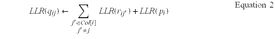
- The method of the check
node function unit 344 calculating the LLR rij of themessage 424 of the parity-check node 423 is given by thefollowing equation 3.
- To calculate the parity-check message according to the
equation 3, the mathematical function as defined by theequation 4 is necessary.
- The parity-check message derived from the
equation 3 is transferred to the bitnode function unit 342. The bitnode function unit 342 calculates the bit message using the updated parity-check message and the initial bit message, and transfers a new bit message to the check node function unit. This operation is repeated a predetermined number of times to obtain the final parity-check message. The bitnode function unit 342 calculates the LLR of the information bit of each code word through the final parity-check message according to thefollowing equation 5. The value of the corresponding bit is then determined from the LLR.
- Once all the bit values of the code word are determined, a new code word is constructed using the bit values and is fed into the
parity checker 343. Theparity checker 343 calculates a syndrome for the code word to perform a parity check. With a non-zero syndrome for the code word, theparity checker 343 determines that the decoding of the code word is a failure. If the parity check is successful, the information bit part is extracted from the code word and transferred. - To implement the above-stated decoding algorithm in hardware, the
respective message calculators LLR calculator 341 receives a soft decision input and calculates the LLR of the soft decision output. The output of theLLR calculator 341 is a soft decision output, so the bitnode function unit 342 needs a summator for summating soft decision inputs according to theequations node function unit 344 must receive a soft decision input and the function of theequation 4 receives the soft decision input and generates a soft decision output. - The
equation 4, which is not a linear function, cannot be implemented with the basic calculation blocks in hardware. To solve this problem, the function of theequation 4 can employ a ROM that receives as many inputs as the number of bits representing the soft decision input and generates as many outputs as the number of bits representing the soft decision output. Accordingly, the implementation cost of the check node function unit is greatly dependent upon the size of the ROM that is determined by the resolution of representing soft decision input and soft decision output. - The present invention proposes a check node function unit not using the ROM. For this purpose, the function of the
equation 4 is implemented with basic calculation blocks. The basic calculation blocks include multipliers and summators. The multipliers are considerably high in price relative to the summators, and not preferably used in the present invention. Hence, powers of n for the soft decision input cannot be used, and only the linear function can be implemented. For that reason, the function of theequation 4 is divided into intervals, and the value of the linear approximation function for each interval is then calculated to determine the checknode function unit 424. The inverse function of theequation 4 is necessary for the calculation of the checknode function unit 424. The inverse function of theequation 4 is the same as theequation 4, so the input of the calculator of theequation 4 must be equal in the number of bits to the output. - The present invention proposes an interval division method as illustrated in FIG. 5 for the linear approximation of the
equation 4. Theactual function 510 of theequation 4 defines only the positive values because it has an absolute value as an input. So, thefunction 510 of theequation 4 is a monotonically decreasing function that decreases with the same slope of the exponential function. The interval for the linear approximation Ii is divided as expressed in the following equation 6 so as to have an exponential size. In the equation 6, n1 is the length of a word expressing the input value, i.e., the word length; and n2 is the bit corresponding to the minimum resolution of decimal places expressing the input value. The minimum resolution that can be expressed by n2 is 2−n 2. - Equation 6
- I i=└2K+l2K+1+i ┘, i∈{0, . . . , n 1−1}, K=−n 2
- The accurate function value of the
equation 4 for both boundary values of each interval Ii is necessary. The coordinates for both end points of the interval are given, so the linear approximation equation can be defined by the following equation 7. - Equation 7
- y=s i γ+x i , i∈{0, . . . , |{I}|−1}, r∈I i
- From the equation 7, slope s i and interval boundary value xi are defined for each interval. First, the slope s, is defined as the following equation 8.

- The ROUND function of the equation 8 is a function for designating an input as the most approximate one of the binary numbers given by 2 −n 2 as the minimum resolution. The ROUND function is given by the following equation 9.

- The boundary value x i is derived from the slope si and xi−1 as in the following equation 10.
- Equation 10
- x l=ROUND((2K+n 1 −1−2K+n 1 −i+1)s i +x i−1 , n 2), i≧1,
- x 0=ROUND(Φ(2K+n 1 ), n 2)
- FIG. 6 illustrates a
circuit 600 for calculating the function value of theequation 4 using the slope and the boundary value given by the equations 8 and 10, respectively. The soft decision inputs are all positive real values, so aninput memory 610 inverts the sign of the negative (−) numbers. Namely, when the value of the most significant bit (MSB) is “1”, the memory value of theinput memory 610 is increased by one and theinput memory 610 performs a 1's complement operation. The value of theinput memory 610 is multiplied by the slope s, of each interval at amultiplier 630, and is added to the interval boundary value generated from aboundary value memory 620 by anadder 640 to determine the function value of theequation 4. Finally, to investigate the interval range of the input value in theinput memory 610, a multiplexor (MUX) 650 for selecting the on/off state of a switch according to the MSB selects an accurate function value and outputs the selected function value. Themultiplexor 650 outputs the first calculated value when the bit of the highest order other than 0 in the input memory is the first bit, or the second calculated value when the bit of the highest order other than 0 is the second bit. In this manner, the on/off state of the switch for every bit can be determined. - The unsolved problem in the above-stated method is the use of multipliers. Typically, the binary multiplier can be implemented with bit shifters and summators. Namely, for multiplication by 1.5, the input word is shifted to the right side by one bit for multiplication by 0.5 which is then added to itself to result in a binary number, which has a 1.5-fold value of the input word. In the same way, the bits of the input word are shifted to achieve a multiplication by 2. The slope is rounded off to a binary number from the equation 8 and the input word is a binary number, so the multiplier can be replaced with a summator and a shifter. Because the number of slopes is limited, summators and shifters are preferably used instead of a general-purpose multiplier in the aspect of curtailment of hardware expenses.
- FIG. 7 shows a
circuit 700 derived by simplifying the calculator of FIG. 6 through a curtailment of hardware expenses. Aninput memory 710 has the same function as theinput memory 610 of FIG. 6. Asummator 740 for summating the boundary values also has the same function as thesummator 640 of FIG. 6. A slope calculator andmultiplier 730 calculates a slope used for multiplication from the bit of the highest order other than “0” in the input of the input memory, and multiplies the slope value by way of the shifter and the summator to generate anoutput 840. Aboundary calculator 720 calculates aboundary value 960 from the bit of the highest order other than “0” in the input of the input memory. FIG. 8 shows the slope calculator andmultiplier 730 of the present invention. Assuming that the leftmost bit is the MSB (Little Endian), aninput memory 810 represents the same block as theinput memory 710 of FIG. 7. Aslope calculator 820 comprises abit shifter 821, aground 822 representing “0”, aword negater 823, and aswitch 824 functioning as a multiplexor. Eachbit shifter 821 includes all bit shifters necessary for constructing each slope. Theground 822 represents a value of “0” usable in the slope calculator. The word negater 823 is used for representing the slope. Theswitches 824 combine the result values from the respective shifters to obtain the final result value. The on/off state of the switches is determined from the value of the slope corresponding to a selected interval of the input value. Thus the hardware resources such as shifters and summators frequently used in the calculation of each slope can be reduced. FIG. 9 shows theboundary calculator 720 of the present invention. Theboundary calculator 720 comprises abit shifter 910, aground 920 representing “0”, aword negater 930, and aswitch 940 functioning as a multiplexor. Eachbit shifter 910 includes all bit shifters necessary for constructing each boundary value. Theground 920 represents a value of “0” usable in the calculation of the boundary value. The word negater 930 is used for representing the boundary value. Theswitches 940 combine the result values from the respective shifters to obtain the final result value. The on/off state of the switches is determined from the boundary value corresponding to a selected interval of the input value. Thus the hardware resources such as shifters and summators frequently used in the calculation of each boundary value can be reduced. The connection state offinal summators - While this invention has been described in connection with what is presently considered to be the most practical and preferred embodiment, it is to be understood that the invention is not limited to the disclosed embodiments, but, on the contrary, is intended to cover various modifications and equivalent arrangements included within the spirit and scope of the appended claims.
- As described above, the present invention rapidly calculates the parity-check message by sharing the resources of the summator and the shifter, relative to the method of implementing a nonlinear function for calculation of the parity-check message with ROMs. The use of the summator and the shift as a shared resource reduces the required hardware resources more than with the use of a multiplier. The present invention uses the power of 2 as a boundary value of the interval divided for a linear approximation, thereby simplifying the circuits of the slope calculator and the boundary calculator and greatly reducing errors caused by approximation. The method of the present invention can be applied to all the monotonic functions and, particularly, exponentially increasing or decreasing nonlinear functions.
Claims (10)


Applications Claiming Priority (2)
| Application Number | Priority Date | Filing Date | Title |
|---|---|---|---|
| KR10-2002-0083721A KR100502608B1 (en) | 2002-12-24 | 2002-12-24 | A Simplified Massage-Passing Decoder for Low-Density Parity-Check Codes |
| KR2002-83721 | 2002-12-24 |
Publications (2)
| Publication Number | Publication Date |
|---|---|
| US20040123230A1 true US20040123230A1 (en) | 2004-06-24 |
| US7178081B2 US7178081B2 (en) | 2007-02-13 |
Family
ID=32588926
Family Applications (1)
| Application Number | Title | Priority Date | Filing Date |
|---|---|---|---|
| US10/696,897 Expired - Fee Related US7178081B2 (en) | 2002-12-24 | 2003-10-29 | Simplified message-passing decoder for low-density parity-check codes |
Country Status (2)
| Country | Link |
|---|---|
| US (1) | US7178081B2 (en) |
| KR (1) | KR100502608B1 (en) |
Cited By (30)
| Publication number | Priority date | Publication date | Assignee | Title |
|---|---|---|---|---|
| US20060117240A1 (en) * | 2004-11-10 | 2006-06-01 | Vladimir Novichkov | Hierarchical design and layout optimizations for high throughput parallel LDPC decoders |
| US20090132887A1 (en) * | 2005-07-13 | 2009-05-21 | Mitsubishi Electric Corporation | Communication Apparatus and Decoding Method |
| US20120290891A1 (en) * | 2011-05-12 | 2012-11-15 | Nextwill | Method and apparatus for decoding low density parity check code |
| US8935598B1 (en) * | 2013-03-12 | 2015-01-13 | Pmc-Sierra Us, Inc. | System and method for adaptive check node approximation in LDPC decoding |
| US8984376B1 (en) | 2013-03-14 | 2015-03-17 | Pmc-Sierra Us, Inc. | System and method for avoiding error mechanisms in layered iterative decoding |
| US8984365B1 (en) | 2013-03-14 | 2015-03-17 | Pmc-Sierra Us, Inc. | System and method for reduced memory storage in LDPC decoding |
| US8990661B1 (en) | 2013-03-05 | 2015-03-24 | Pmc-Sierra Us, Inc. | Layer specific attenuation factor LDPC decoder |
| US8995302B1 (en) | 2013-01-16 | 2015-03-31 | Pmc-Sierra Us, Inc. | Method and apparatus for translated routing in an interconnect switch |
| US9092353B1 (en) | 2013-01-29 | 2015-07-28 | Pmc-Sierra Us, Inc. | Apparatus and method based on LDPC codes for adjusting a correctable raw bit error rate limit in a memory system |
| US9128858B1 (en) | 2013-01-29 | 2015-09-08 | Pmc-Sierra Us, Inc. | Apparatus and method for adjusting a correctable raw bit error rate limit in a memory system using strong log-likelihood (LLR) values |
| US9235467B2 (en) | 2013-03-15 | 2016-01-12 | Pmc-Sierra Us, Inc. | System and method with reference voltage partitioning for low density parity check decoding |
| US9397701B1 (en) | 2013-03-11 | 2016-07-19 | Microsemi Storage Solutions (Us), Inc. | System and method for lifetime specific LDPC decoding |
| US9417804B2 (en) | 2014-07-07 | 2016-08-16 | Microsemi Storage Solutions (Us), Inc. | System and method for memory block pool wear leveling |
| US9450610B1 (en) | 2013-03-15 | 2016-09-20 | Microsemi Storage Solutions (Us), Inc. | High quality log likelihood ratios determined using two-index look-up table |
| US9454414B2 (en) | 2013-03-15 | 2016-09-27 | Microsemi Storage Solutions (Us), Inc. | System and method for accumulating soft information in LDPC decoding |
| US9590656B2 (en) | 2013-03-15 | 2017-03-07 | Microsemi Storage Solutions (Us), Inc. | System and method for higher quality log likelihood ratios in LDPC decoding |
| US9799405B1 (en) | 2015-07-29 | 2017-10-24 | Ip Gem Group, Llc | Nonvolatile memory system with read circuit for performing reads using threshold voltage shift read instruction |
| US9813080B1 (en) | 2013-03-05 | 2017-11-07 | Microsemi Solutions (U.S.), Inc. | Layer specific LDPC decoder |
| US9886214B2 (en) | 2015-12-11 | 2018-02-06 | Ip Gem Group, Llc | Nonvolatile memory system with erase suspend circuit and method for erase suspend management |
| US9892794B2 (en) | 2016-01-04 | 2018-02-13 | Ip Gem Group, Llc | Method and apparatus with program suspend using test mode |
| US9899092B2 (en) | 2016-01-27 | 2018-02-20 | Ip Gem Group, Llc | Nonvolatile memory system with program step manager and method for program step management |
| US20180159555A1 (en) * | 2016-12-01 | 2018-06-07 | Western Digital Technologies, Inc. | Configurable ecc decoder |
| US10157677B2 (en) | 2016-07-28 | 2018-12-18 | Ip Gem Group, Llc | Background reference positioning and local reference positioning using threshold voltage shift read |
| US10218384B2 (en) | 2016-12-01 | 2019-02-26 | Sandisk Technologies Llc | ECC decoder with multiple decoding modes |
| US10230396B1 (en) | 2013-03-05 | 2019-03-12 | Microsemi Solutions (Us), Inc. | Method and apparatus for layer-specific LDPC decoding |
| US10236915B2 (en) | 2016-07-29 | 2019-03-19 | Microsemi Solutions (U.S.), Inc. | Variable T BCH encoding |
| US10291263B2 (en) | 2016-07-28 | 2019-05-14 | Ip Gem Group, Llc | Auto-learning log likelihood ratio |
| US10332613B1 (en) | 2015-05-18 | 2019-06-25 | Microsemi Solutions (Us), Inc. | Nonvolatile memory system with retention monitor |
| US10523366B1 (en) * | 2016-08-31 | 2019-12-31 | Marvell International Ltd. | Message-passing decoder with fast convergence and reduced storage |
| US10565040B2 (en) | 2016-12-01 | 2020-02-18 | Western Digital Technologies, Inc. | ECC decoder with selective component disabling based on decoding message resolution |
Families Citing this family (51)
| Publication number | Priority date | Publication date | Assignee | Title |
|---|---|---|---|---|
| KR100594818B1 (en) * | 2004-04-13 | 2006-07-03 | 한국전자통신연구원 | A Decoding Apparatus of Low-Density Parity-Check Codes Using Sequential Decoding, and a method thereof |
| KR100762619B1 (en) * | 2004-05-21 | 2007-10-01 | 삼성전자주식회사 | Apparatus and Method for decoding symbol with Low Density Parity Check Code |
| JP4138700B2 (en) * | 2004-05-31 | 2008-08-27 | 株式会社東芝 | Decoding device and decoding circuit |
| JP4282558B2 (en) * | 2004-06-30 | 2009-06-24 | 株式会社東芝 | Low density parity check code decoder and method |
| KR100739684B1 (en) * | 2004-08-05 | 2007-07-13 | 삼성전자주식회사 | Apparatus and Method for generating Low Density Parity Check Matrix |
| GB0418263D0 (en) * | 2004-08-16 | 2004-09-15 | Ttp Communications Ltd | Soft decision enhancement |
| JP4551740B2 (en) * | 2004-11-08 | 2010-09-29 | 株式会社東芝 | Low density parity check code decoder and method |
| JP2006339799A (en) * | 2005-05-31 | 2006-12-14 | Toshiba Corp | Irregular low density parity check code decoder and decoding method |
| JP4526450B2 (en) * | 2005-06-30 | 2010-08-18 | ルネサスエレクトロニクス株式会社 | Decoding apparatus, method, and program |
| KR100804793B1 (en) * | 2005-10-07 | 2008-02-20 | 삼성전자주식회사 | Method for updating Check Node in Low Density Parity Check Decoder |
| US8122315B2 (en) * | 2005-12-01 | 2012-02-21 | Electronics And Telecommunications Research Institute | LDPC decoding apparatus and method using type-classified index |
| KR20070084951A (en) * | 2006-02-22 | 2007-08-27 | 삼성전자주식회사 | Apparatus and method for receiving signal in a communication system |
| EP1990932A1 (en) * | 2006-02-27 | 2008-11-12 | Matsushita Electric Industrial Co., Ltd. | Radio communication device and relay transmission method |
| KR101187070B1 (en) | 2006-04-21 | 2012-09-27 | 엘지전자 주식회사 | Method for encoding using parity check matrix |
| US20080028282A1 (en) * | 2006-07-25 | 2008-01-31 | Legend Silicon | receiver architecture having a ldpc decoder with an improved llr update method for memory reduction |
| US7827461B1 (en) * | 2006-09-18 | 2010-11-02 | Marvell International Ltd. | Low-density parity-check decoder apparatus |
| US9116823B2 (en) | 2006-12-06 | 2015-08-25 | Intelligent Intellectual Property Holdings 2 Llc | Systems and methods for adaptive error-correction coding |
| US9495241B2 (en) | 2006-12-06 | 2016-11-15 | Longitude Enterprise Flash S.A.R.L. | Systems and methods for adaptive data storage |
| US8443134B2 (en) | 2006-12-06 | 2013-05-14 | Fusion-Io, Inc. | Apparatus, system, and method for graceful cache device degradation |
| US8296337B2 (en) | 2006-12-06 | 2012-10-23 | Fusion-Io, Inc. | Apparatus, system, and method for managing data from a requesting device with an empty data token directive |
| US8719501B2 (en) | 2009-09-08 | 2014-05-06 | Fusion-Io | Apparatus, system, and method for caching data on a solid-state storage device |
| US8706968B2 (en) | 2007-12-06 | 2014-04-22 | Fusion-Io, Inc. | Apparatus, system, and method for redundant write caching |
| US8489817B2 (en) | 2007-12-06 | 2013-07-16 | Fusion-Io, Inc. | Apparatus, system, and method for caching data |
| US9104599B2 (en) | 2007-12-06 | 2015-08-11 | Intelligent Intellectual Property Holdings 2 Llc | Apparatus, system, and method for destaging cached data |
| KR100938068B1 (en) * | 2007-01-30 | 2010-01-21 | 삼성전자주식회사 | Apparatus and method for receiving signal in a communication system |
| US8359522B2 (en) | 2007-05-01 | 2013-01-22 | Texas A&M University System | Low density parity check decoder for regular LDPC codes |
| TW200908569A (en) * | 2007-05-21 | 2009-02-16 | Ramot At Tel Aviv University Co Ltd | Memory-efficient LDPC decoding |
| US7958429B2 (en) * | 2007-07-02 | 2011-06-07 | Broadcom Corporation | Distributed processing LDPC (low density parity check) decoder |
| US20090070659A1 (en) * | 2007-09-11 | 2009-03-12 | Legend Silicon Corp. | Ldpc decoder with an improved llr update method using a set of relative values free from a shifting action |
| US9519540B2 (en) | 2007-12-06 | 2016-12-13 | Sandisk Technologies Llc | Apparatus, system, and method for destaging cached data |
| US7836226B2 (en) | 2007-12-06 | 2010-11-16 | Fusion-Io, Inc. | Apparatus, system, and method for coordinating storage requests in a multi-processor/multi-thread environment |
| US8316277B2 (en) * | 2007-12-06 | 2012-11-20 | Fusion-Io, Inc. | Apparatus, system, and method for ensuring data validity in a data storage process |
| KR101527114B1 (en) * | 2008-04-02 | 2015-06-08 | 삼성전자주식회사 | Apparatus and method for detecting signal based on lattice reduction capable to support different encoding scheme by stream in a multiple input multiple output wireless communication system |
| US8347167B2 (en) * | 2008-12-19 | 2013-01-01 | Lsi Corporation | Circuits for implementing parity computation in a parallel architecture LDPC decoder |
| US8418019B2 (en) * | 2010-04-19 | 2013-04-09 | Lsi Corporation | Systems and methods for dynamic scaling in a data decoding system |
| US9092337B2 (en) | 2011-01-31 | 2015-07-28 | Intelligent Intellectual Property Holdings 2 Llc | Apparatus, system, and method for managing eviction of data |
| US9003104B2 (en) | 2011-02-15 | 2015-04-07 | Intelligent Intellectual Property Holdings 2 Llc | Systems and methods for a file-level cache |
| US9201677B2 (en) | 2011-05-23 | 2015-12-01 | Intelligent Intellectual Property Holdings 2 Llc | Managing data input/output operations |
| US8874823B2 (en) | 2011-02-15 | 2014-10-28 | Intellectual Property Holdings 2 Llc | Systems and methods for managing data input/output operations |
| US9141527B2 (en) | 2011-02-25 | 2015-09-22 | Intelligent Intellectual Property Holdings 2 Llc | Managing cache pools |
| US9251052B2 (en) | 2012-01-12 | 2016-02-02 | Intelligent Intellectual Property Holdings 2 Llc | Systems and methods for profiling a non-volatile cache having a logical-to-physical translation layer |
| US10102117B2 (en) | 2012-01-12 | 2018-10-16 | Sandisk Technologies Llc | Systems and methods for cache and storage device coordination |
| US9767032B2 (en) | 2012-01-12 | 2017-09-19 | Sandisk Technologies Llc | Systems and methods for cache endurance |
| US9251086B2 (en) | 2012-01-24 | 2016-02-02 | SanDisk Technologies, Inc. | Apparatus, system, and method for managing a cache |
| US10359972B2 (en) | 2012-08-31 | 2019-07-23 | Sandisk Technologies Llc | Systems, methods, and interfaces for adaptive persistence |
| US9116812B2 (en) | 2012-01-27 | 2015-08-25 | Intelligent Intellectual Property Holdings 2 Llc | Systems and methods for a de-duplication cache |
| US10019353B2 (en) | 2012-03-02 | 2018-07-10 | Longitude Enterprise Flash S.A.R.L. | Systems and methods for referencing data on a storage medium |
| US10339056B2 (en) | 2012-07-03 | 2019-07-02 | Sandisk Technologies Llc | Systems, methods and apparatus for cache transfers |
| US9612966B2 (en) | 2012-07-03 | 2017-04-04 | Sandisk Technologies Llc | Systems, methods and apparatus for a virtual machine cache |
| US9842053B2 (en) | 2013-03-15 | 2017-12-12 | Sandisk Technologies Llc | Systems and methods for persistent cache logging |
| KR102231278B1 (en) | 2017-06-07 | 2021-03-23 | 한국전자통신연구원 | Low density parity check decoder using binary-logarithm and decoding method thereof |
Citations (3)
| Publication number | Priority date | Publication date | Assignee | Title |
|---|---|---|---|---|
| US6633856B2 (en) * | 2001-06-15 | 2003-10-14 | Flarion Technologies, Inc. | Methods and apparatus for decoding LDPC codes |
| US6938196B2 (en) * | 2001-06-15 | 2005-08-30 | Flarion Technologies, Inc. | Node processors for use in parity check decoders |
| US7013116B2 (en) * | 2002-06-26 | 2006-03-14 | Lucent Technologies Inc. | MIMO systems having a channel decoder matched to a MIMO detector |
Family Cites Families (3)
| Publication number | Priority date | Publication date | Assignee | Title |
|---|---|---|---|---|
| JP3590310B2 (en) | 1999-12-07 | 2004-11-17 | シャープ株式会社 | Concatenated convolutional code decoder |
| KR20020051549A (en) | 2000-12-22 | 2002-06-29 | 오길록 | Quantization and metric estimation method for iterative decoder |
| KR20020072628A (en) | 2001-03-12 | 2002-09-18 | 학교법인 인하학원 | Path metric normalization method for a high speed SOVA decoder |
-
2002
- 2002-12-24 KR KR10-2002-0083721A patent/KR100502608B1/en not_active IP Right Cessation
-
2003
- 2003-10-29 US US10/696,897 patent/US7178081B2/en not_active Expired - Fee Related
Patent Citations (3)
| Publication number | Priority date | Publication date | Assignee | Title |
|---|---|---|---|---|
| US6633856B2 (en) * | 2001-06-15 | 2003-10-14 | Flarion Technologies, Inc. | Methods and apparatus for decoding LDPC codes |
| US6938196B2 (en) * | 2001-06-15 | 2005-08-30 | Flarion Technologies, Inc. | Node processors for use in parity check decoders |
| US7013116B2 (en) * | 2002-06-26 | 2006-03-14 | Lucent Technologies Inc. | MIMO systems having a channel decoder matched to a MIMO detector |
Cited By (36)
| Publication number | Priority date | Publication date | Assignee | Title |
|---|---|---|---|---|
| US20060117240A1 (en) * | 2004-11-10 | 2006-06-01 | Vladimir Novichkov | Hierarchical design and layout optimizations for high throughput parallel LDPC decoders |
| US20090132887A1 (en) * | 2005-07-13 | 2009-05-21 | Mitsubishi Electric Corporation | Communication Apparatus and Decoding Method |
| US8132080B2 (en) | 2005-07-13 | 2012-03-06 | Mitsubishi Electric Corporation | Communication apparatus and decoding method |
| US20120290891A1 (en) * | 2011-05-12 | 2012-11-15 | Nextwill | Method and apparatus for decoding low density parity check code |
| US8910011B2 (en) * | 2011-05-12 | 2014-12-09 | Electronics And Telecommunications Research Institute | Method and apparatus for decoding low density parity check code |
| US8995302B1 (en) | 2013-01-16 | 2015-03-31 | Pmc-Sierra Us, Inc. | Method and apparatus for translated routing in an interconnect switch |
| US9128858B1 (en) | 2013-01-29 | 2015-09-08 | Pmc-Sierra Us, Inc. | Apparatus and method for adjusting a correctable raw bit error rate limit in a memory system using strong log-likelihood (LLR) values |
| US9092353B1 (en) | 2013-01-29 | 2015-07-28 | Pmc-Sierra Us, Inc. | Apparatus and method based on LDPC codes for adjusting a correctable raw bit error rate limit in a memory system |
| US9448881B1 (en) | 2013-01-29 | 2016-09-20 | Microsemi Storage Solutions (Us), Inc. | Memory controller and integrated circuit device for correcting errors in data read from memory cells |
| US8990661B1 (en) | 2013-03-05 | 2015-03-24 | Pmc-Sierra Us, Inc. | Layer specific attenuation factor LDPC decoder |
| US10230396B1 (en) | 2013-03-05 | 2019-03-12 | Microsemi Solutions (Us), Inc. | Method and apparatus for layer-specific LDPC decoding |
| US9813080B1 (en) | 2013-03-05 | 2017-11-07 | Microsemi Solutions (U.S.), Inc. | Layer specific LDPC decoder |
| US9397701B1 (en) | 2013-03-11 | 2016-07-19 | Microsemi Storage Solutions (Us), Inc. | System and method for lifetime specific LDPC decoding |
| US8935598B1 (en) * | 2013-03-12 | 2015-01-13 | Pmc-Sierra Us, Inc. | System and method for adaptive check node approximation in LDPC decoding |
| US8984365B1 (en) | 2013-03-14 | 2015-03-17 | Pmc-Sierra Us, Inc. | System and method for reduced memory storage in LDPC decoding |
| US8984376B1 (en) | 2013-03-14 | 2015-03-17 | Pmc-Sierra Us, Inc. | System and method for avoiding error mechanisms in layered iterative decoding |
| US9590656B2 (en) | 2013-03-15 | 2017-03-07 | Microsemi Storage Solutions (Us), Inc. | System and method for higher quality log likelihood ratios in LDPC decoding |
| US9454414B2 (en) | 2013-03-15 | 2016-09-27 | Microsemi Storage Solutions (Us), Inc. | System and method for accumulating soft information in LDPC decoding |
| US9450610B1 (en) | 2013-03-15 | 2016-09-20 | Microsemi Storage Solutions (Us), Inc. | High quality log likelihood ratios determined using two-index look-up table |
| US9235467B2 (en) | 2013-03-15 | 2016-01-12 | Pmc-Sierra Us, Inc. | System and method with reference voltage partitioning for low density parity check decoding |
| US9417804B2 (en) | 2014-07-07 | 2016-08-16 | Microsemi Storage Solutions (Us), Inc. | System and method for memory block pool wear leveling |
| US10332613B1 (en) | 2015-05-18 | 2019-06-25 | Microsemi Solutions (Us), Inc. | Nonvolatile memory system with retention monitor |
| US9799405B1 (en) | 2015-07-29 | 2017-10-24 | Ip Gem Group, Llc | Nonvolatile memory system with read circuit for performing reads using threshold voltage shift read instruction |
| US10152273B2 (en) | 2015-12-11 | 2018-12-11 | Ip Gem Group, Llc | Nonvolatile memory controller and method for erase suspend management that increments the number of program and erase cycles after erase suspend |
| US9886214B2 (en) | 2015-12-11 | 2018-02-06 | Ip Gem Group, Llc | Nonvolatile memory system with erase suspend circuit and method for erase suspend management |
| US9892794B2 (en) | 2016-01-04 | 2018-02-13 | Ip Gem Group, Llc | Method and apparatus with program suspend using test mode |
| US9899092B2 (en) | 2016-01-27 | 2018-02-20 | Ip Gem Group, Llc | Nonvolatile memory system with program step manager and method for program step management |
| US10157677B2 (en) | 2016-07-28 | 2018-12-18 | Ip Gem Group, Llc | Background reference positioning and local reference positioning using threshold voltage shift read |
| US10283215B2 (en) | 2016-07-28 | 2019-05-07 | Ip Gem Group, Llc | Nonvolatile memory system with background reference positioning and local reference positioning |
| US10291263B2 (en) | 2016-07-28 | 2019-05-14 | Ip Gem Group, Llc | Auto-learning log likelihood ratio |
| US10236915B2 (en) | 2016-07-29 | 2019-03-19 | Microsemi Solutions (U.S.), Inc. | Variable T BCH encoding |
| US10523366B1 (en) * | 2016-08-31 | 2019-12-31 | Marvell International Ltd. | Message-passing decoder with fast convergence and reduced storage |
| US20180159555A1 (en) * | 2016-12-01 | 2018-06-07 | Western Digital Technologies, Inc. | Configurable ecc decoder |
| US10218384B2 (en) | 2016-12-01 | 2019-02-26 | Sandisk Technologies Llc | ECC decoder with multiple decoding modes |
| US10530393B2 (en) * | 2016-12-01 | 2020-01-07 | Western Digital Technologies, Inc. | Configurable ECC decoder |
| US10565040B2 (en) | 2016-12-01 | 2020-02-18 | Western Digital Technologies, Inc. | ECC decoder with selective component disabling based on decoding message resolution |
Also Published As
| Publication number | Publication date |
|---|---|
| KR20040056972A (en) | 2004-07-01 |
| KR100502608B1 (en) | 2005-07-20 |
| US7178081B2 (en) | 2007-02-13 |
Similar Documents
| Publication | Publication Date | Title |
|---|---|---|
| US7178081B2 (en) | Simplified message-passing decoder for low-density parity-check codes | |
| US8473806B1 (en) | Layered quasi-cyclic LDPC decoder with reduced-complexity circular shifter | |
| US8438459B2 (en) | Apparatus and method for decoding using channel code | |
| CN101032082B (en) | Method and apparatus for encoding and decoding data | |
| US7484158B2 (en) | Method for decoding a low-density parity check (LDPC) codeword | |
| US7203897B2 (en) | Method and apparatus for encoding and decoding data | |
| CN101079638B (en) | Low density parity check decoding system and method for reducing complexity | |
| US8166363B2 (en) | Decoding device and method | |
| US6771197B1 (en) | Quantizing signals using sparse generator factor graph codes | |
| US8151161B2 (en) | Apparatus and method for decoding using channel code | |
| US8108760B2 (en) | Decoding of linear codes with parity check matrix | |
| US20050149840A1 (en) | Apparatus for encoding and decoding of low-density parity-check codes, and method thereof | |
| US20050204272A1 (en) | Decoding apparatus and method and information processing apparatus and method | |
| US8205130B2 (en) | Decoding apparatus | |
| US8099645B2 (en) | LDPC codes and stochastic decoding for optical transmission | |
| US7188297B2 (en) | Method and apparatus for encoding and decoding data | |
| CN109586732B (en) | System and method for encoding and decoding LDPC codes with medium and short codes | |
| US7493548B2 (en) | Method and apparatus for encoding and decoding data | |
| CN105763203A (en) | Multi-element LDPC code decoding method based on hard reliability information | |
| JP4832447B2 (en) | Decoding apparatus and method using channel code | |
| US20020002695A1 (en) | Method and system for decoding | |
| CN105871385A (en) | LDPC convolutional code construction method | |
| JP5385944B2 (en) | Decoder | |
| KR101208505B1 (en) | Method of decoding using LDPC code and apparatus thereof | |
| JP4973647B2 (en) | Error correction code decoding evaluation apparatus |
Legal Events
| Date | Code | Title | Description |
|---|---|---|---|
| AS | Assignment |
Owner name: ELECTRONICS AND TELECOMMUNICATIONS RESEARCH INSTIT Free format text: ASSIGNMENT OF ASSIGNORS INTEREST;ASSIGNORS:KIM, YUN-HEE;KIM, KWANG-SOON;CHANG, KYUNG-HI;REEL/FRAME:014658/0905;SIGNING DATES FROM 20030725 TO 20030813 |
|
| AS | Assignment |
Owner name: ELECTRONICS AND TELECOMMUNICATIONS RESEARCH INSTIT Free format text: ASSIGNMENT OF ASSIGNORS INTEREST;ASSIGNORS:LEE, SANG-HYUN;KIM, YUN-HEE;KIM, KWANG-SOON;AND OTHERS;REEL/FRAME:015557/0605;SIGNING DATES FROM 20030725 TO 20030813 |
|
| FEPP | Fee payment procedure |
Free format text: PAYOR NUMBER ASSIGNED (ORIGINAL EVENT CODE: ASPN); ENTITY STATUS OF PATENT OWNER: SMALL ENTITY |
|
| FPAY | Fee payment |
Year of fee payment: 4 |
|
| FPAY | Fee payment |
Year of fee payment: 8 |
|
| FEPP | Fee payment procedure |
Free format text: MAINTENANCE FEE REMINDER MAILED (ORIGINAL EVENT CODE: REM.); ENTITY STATUS OF PATENT OWNER: SMALL ENTITY |
|
| LAPS | Lapse for failure to pay maintenance fees |
Free format text: PATENT EXPIRED FOR FAILURE TO PAY MAINTENANCE FEES (ORIGINAL EVENT CODE: EXP.); ENTITY STATUS OF PATENT OWNER: SMALL ENTITY |
|
| STCH | Information on status: patent discontinuation |
Free format text: PATENT EXPIRED DUE TO NONPAYMENT OF MAINTENANCE FEES UNDER 37 CFR 1.362 |
|
| FP | Lapsed due to failure to pay maintenance fee |
Effective date: 20190213 |