US5278988A - Automated receiver monitoring method and apparatus - Google Patents
Automated receiver monitoring method and apparatus Download PDFInfo
- Publication number
- US5278988A US5278988A US07/715,366 US71536691A US5278988A US 5278988 A US5278988 A US 5278988A US 71536691 A US71536691 A US 71536691A US 5278988 A US5278988 A US 5278988A
- Authority
- US
- United States
- Prior art keywords
- identified
- receiver
- transmitting station
- tuned frequency
- recited
- Prior art date
- Legal status (The legal status is an assumption and is not a legal conclusion. Google has not performed a legal analysis and makes no representation as to the accuracy of the status listed.)
- Expired - Fee Related
Links
Images

Classifications
-
- H—ELECTRICITY
- H04—ELECTRIC COMMUNICATION TECHNIQUE
- H04H—BROADCAST COMMUNICATION
- H04H60/00—Arrangements for broadcast applications with a direct linking to broadcast information or broadcast space-time; Broadcast-related systems
- H04H60/35—Arrangements for identifying or recognising characteristics with a direct linkage to broadcast information or to broadcast space-time, e.g. for identifying broadcast stations or for identifying users
- H04H60/38—Arrangements for identifying or recognising characteristics with a direct linkage to broadcast information or to broadcast space-time, e.g. for identifying broadcast stations or for identifying users for identifying broadcast time or space
- H04H60/41—Arrangements for identifying or recognising characteristics with a direct linkage to broadcast information or to broadcast space-time, e.g. for identifying broadcast stations or for identifying users for identifying broadcast time or space for identifying broadcast space, i.e. broadcast channels, broadcast stations or broadcast areas
- H04H60/44—Arrangements for identifying or recognising characteristics with a direct linkage to broadcast information or to broadcast space-time, e.g. for identifying broadcast stations or for identifying users for identifying broadcast time or space for identifying broadcast space, i.e. broadcast channels, broadcast stations or broadcast areas for identifying broadcast stations
-
- H—ELECTRICITY
- H04—ELECTRIC COMMUNICATION TECHNIQUE
- H04H—BROADCAST COMMUNICATION
- H04H60/00—Arrangements for broadcast applications with a direct linking to broadcast information or broadcast space-time; Broadcast-related systems
- H04H60/35—Arrangements for identifying or recognising characteristics with a direct linkage to broadcast information or to broadcast space-time, e.g. for identifying broadcast stations or for identifying users
- H04H60/38—Arrangements for identifying or recognising characteristics with a direct linkage to broadcast information or to broadcast space-time, e.g. for identifying broadcast stations or for identifying users for identifying broadcast time or space
- H04H60/40—Arrangements for identifying or recognising characteristics with a direct linkage to broadcast information or to broadcast space-time, e.g. for identifying broadcast stations or for identifying users for identifying broadcast time or space for identifying broadcast time
-
- H—ELECTRICITY
- H04—ELECTRIC COMMUNICATION TECHNIQUE
- H04H—BROADCAST COMMUNICATION
- H04H60/00—Arrangements for broadcast applications with a direct linking to broadcast information or broadcast space-time; Broadcast-related systems
- H04H60/35—Arrangements for identifying or recognising characteristics with a direct linkage to broadcast information or to broadcast space-time, e.g. for identifying broadcast stations or for identifying users
- H04H60/49—Arrangements for identifying or recognising characteristics with a direct linkage to broadcast information or to broadcast space-time, e.g. for identifying broadcast stations or for identifying users for identifying locations
- H04H60/50—Arrangements for identifying or recognising characteristics with a direct linkage to broadcast information or to broadcast space-time, e.g. for identifying broadcast stations or for identifying users for identifying locations of broadcast or relay stations
Definitions
- the invention relates generally to a method and apparatus for monitoring receivers, and more particularly to methods and apparatus for determining the particular transmitting station from which program signals are received and translated by a monitored receiver and including automobile and portable receivers.
- Important objects of the present invention are to provide a method and apparatus for monitoring receivers that overcome many of the disadvantages of the prior art systems; to provide such method and apparatus for monitoring receivers that can be effectively and efficiently configured for monitoring mobile receivers; to provide a method and apparatus for determining a particular transmitting station from which program signals are received and translated by a monitored receiver within a test area that automates the identification of new transmitting stations.
- a transmitter characteristic table is stored in the receiver monitor apparatus.
- the transmitter characteristic table includes a corresponding transmitting station identification stored with a predefined subarea of a plurality of predefined subareas within the test area for each predetermined tuned frequency of the monitored receiver.
- a tuned frequency of the monitored receiver is identified and the particular transmitting station corresponding to the identified tuned frequency is identified responsive to both the identified tuned frequency of the monitored receiver and the stored transmitter characteristic table.
- the identified transmitting station data is stored with time of occurrence data.
- FIG. 1 is a block diagram of a receiver monitoring system according to the present invention
- FIG. 2 is a transmitter characteristic table illustrating transmitting stations with a corresponding transmitting frequency by predefined subareas of a geographical test area of the receiver monitoring system of FIG. 1 to perform the method of the present invention
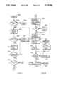
- FIG. 3 is a block diagram illustrating a receiver monitoring apparatus of the receiver monitoring system of FIG. 1;
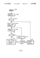
- FIGS. 4-5 are flow charts illustrating logical steps performed by the receiver monitoring apparatus of the receiver monitoring system of FIG. 1 in accordance with methods of the present invention.
- FIG. 6 is a flow chart illustrating logical steps performed by either a central computer or the receiver monitoring apparatus in generating the transmitter characteristic table of the receiver monitoring system of FIG. 1.
- FIG. 1 there is illustrated a block diagram of a new and improved receiver monitoring system according to the invention generally designated by the reference numeral 10. While the receiver monitoring system 10 is depicted and generally described herein for monitoring a mobile radio receiver, the principles of the present invention are also applicable to monitoring television receivers, video cassette recorders and other receivers and television viewing and listening habits of individual audience members or panelists of cooperating households.
- Receiver monitoring system 10 includes a plurality of receiver monitors 1-N generally designated by the reference character 12 coupled to a central computer 14 via communications links generally designated by the reference character 16.
- Each receiver monitor 12 monitors and stores selected, monitored receiver data, for example, such as tuned transmitting station and frequency data, tune-in and tune-out events together with time of occurrence data and identified new transmitters or broadcasting stations within a geographical or test area of the receiver monitor system 10.
- Receiver monitor 12 does not require access to any electrical signal that is only available internally to a monitored receiver 18.
- Central computer 14 collects and processes the monitored data from the receiver monitors 12 to provide market research analysis and reports.
- Central computer 14 utilizes the collected data to update and maintain transmitter characteristic data including additional identified broadcasting stations.
- Central computer 14 periodically resets the real time clocks of the receiver monitor 12 to facilitate accurately time stamping of the monitored receiver data.
- FIG. 1 illustrates a plurality of broadcasting stations or transmitters T1-T8 in the test area of the receiver monitor system 10. An associated transmitting frequency is shown with each of the transmitters T1-T8. As shown, transmitter T1 has a transmitting frequency f1, transmitter T2 has a transmitting frequency f2, transmitter T3 has a transmitting frequency f3, transmitter T4 has a transmitting frequency f4, transmitter T5 has a transmitting frequency f5, transmitter T6 has a transmitting frequency f6, transmitter T7 has the transmitting frequency f3 and transmitter T8 has a transmitting frequency f7.
- test area By dividing the test area into cells or subareas based upon transmitter signal strengths, broadcasting stations or transmitters having the same transmitting frequency, such as frequency f3 for both transmitters T3 and T7, can be distinguished and uniquely identified.
- FIG. 2 is a transmitter characteristic table illustrating a cluster list of the transmitter stations T1-T8 by a plurality of predefined subareas S1-S4 within the test area of the receiver monitor system 10.
- geographic subareas S1-S4 are determined by a unique set of the transmitters T1-T8 that can be received within acceptable signal-to-noise ratios.
- a receiver monitor 12 located within the subarea S1 can receive acceptable transmitted frequency signals f4, f5 from transmitter stations T4 and T5, while other transmitted frequency signals f3, f2, f6, f7 and f3 from transmitter stations T3, T2, T6, T8 and T7 have a signal-to-noise ratio below a predetermined threshold value.
- a receiver monitor 12 located within the subarea S2 can receive acceptable transmitted frequency signals f2, f3 and f5 from transmitter stations T2, T3 and T5.
- a receiver monitor 12 having identified a tuned frequency f3 of its monitored receiver determines its subarea location by tuning another frequency signal within the subareas S2, S3 or S4, for example, by tuning transmitted frequency signal f4 and comparing the detected signal-to-noise ratio to a threshold value. When the detected signal-to-noise ratio is greater than the threshold value, then subarea S3 is identified. Otherwise, another frequency signal within either subarea S2 or S4 is tuned to identify one of the subareas S2 or S4 as the current location. When subarea S3 is identified, then the associated transmitter station is T7.
- receiver monitor 12 includes a frequency synthesized receiver 22 having the same frequency bands (AM and FM) of the monitored receiver 18; a microprocessor 24 for controlling the frequency synthesized receiver 22 and identifying a tuned transmitter; a correlator 26 computes a crosscorrelation of output signals of the monitored receiver 18 and the frequency synthesized receiver 22 under the control of the microprocessor 24; and a nonvolatile random access memory (RAM)/clock cartridge 28 for providing memory for storage of the transmitter characteristic table and monitored data and including a real time clock for providing time of occurrence or a time stamp of any change in channel or other desired monitored parameter.
- Frequency synthesized receiver 22 is connected to the receiving antenna 20 so that the same radio frequency (RF) signals are received by the receiver monitor 12 as the monitored receiver 18.
- Microprocessor 24 controls the frequency synthesized receiver frequency scan until a transmitting station is tuned.
- RF radio frequency
- An audio output signal of the monitored receiver 18 can be applied to the correlator 26 via either a direct connection or a microphone pick-up as indicated at a line labelled MONITORED RECEIVER SIGNAL.
- Frequency synthesized receiver 22 generates a standard audio output that is applied to the correlator 26.
- the audio output signals applied to the correlator 26 are similar.
- a crosscorrelation output signal of the correlator 26 is applied to the microprocessor 24.
- Microprocessor 24 threshold compares the crosscorrelation output signal to determine whether or not the frequency synthesized receiver 22 and the monitored receiver 18 are tuned to the same frequency.
- RAM/clock cartridge 28 includes a battery and advantageously functions as the communications link 16 for bidirectional communications with the central computer 14.
- the real time clock contained in the RAM/CLOCK cartridge 28 is periodically reset by the central computer 14 and the transmitter characteristic table is updated by the central computer 14 to include new broadcasting stations.
- a local oscillator detection circuit 30 receives a RF signal emitted by the monitored receiver 18 via a non-invasive, inductive probe 32.
- a detected local oscillator signal of the circuit 30 is applied to the microprocessor 24 to determine the tuned frequency of the monitored receiver 18.
- the communication links 16 can be used for various conventional arrangements, for example, such as, via telephone lines connected to the public switched telephone network or via mailable memory devices.
- Various commercially available microprocessor devices having standard capabilities can be used for the central computer 14, for example, such as a 80286 microprocessor manufactured and sold by Intel Corporation of Santa Clara, Calif.
- FIGS. 4-5 are flow charts illustrating logical steps performed by the microprocessor 24 in the operation of the receiver monitoring system 10.
- the sequential operations begin as indicated at a block 400.
- Microprocessor 24 monitors the receiver status as indicated at blocks 402 and 404.
- the scanning process begins with scanning first the most often tuned frequencies, or the last tuned frequency as indicated at a block 406.
- the presence of the local oscillator signal is identified as indicated at a block 408.
- an alternate signal source such as a cassette use is stored as indicated at a block 410.
- the tuned frequency is identified as indicated at a block 412.
- a crosscorrelation match is determined as indicated at a block 414.
- a lack of crosscorrelation or no match indicates an alternate signal source, such as a cassette use is stored at block 410.
- a monitored mobile receiver 18 is identified at a decision block 416.
- a monitored mobile receiver when a monitored mobile receiver is identified at block 416 of FIG. 4, then the sequential operations continue following entry point A by comparing the identified tuned frequency with the transmitter characteristic table as indicated at a block 500.
- a tie or more than one corresponding transmitting station is identified as indicated at a decision block 502
- a scan loop is performed to determine the particular subarea location of the monitored receiver 18 as indicated at a block 504.
- the particular subarea is identified as indicated at a block 506 and then the particular corresponding transmitter is identified as indicated at a block 508.
- the sequential operations continue following entry point B, to identify the particular corresponding transmitter at block 508.
- a new transmitted frequency is indicated at a decision block 510 such as transmitter T8, shown in dotted line in FIG. 1.
- the new transmitted frequency is stored with the monitored data in RAM/clock cartridge 28 as indicated at block 512.
- the identified particular corresponding transmitter data is stored as indicated at a block 514.
- a status change of the monitored receiver is determined as indicated at a decision block 516 and monitoring of the identified tuned frequency continues as indicated at a block 518 until a status change is identified. Then the change data is time-stamped and stored as indicated at block 520 and the sequential operations return as indicated at block 522 and the monitoring sequence is repeated.
- a first subarea S(n) S1 is identified as indicated at a block 602 and n is set to 1 as indicated at a block 604.
- a scan loop for the subarea S1 is performed by the microprocessor 24 located within the subarea S1 or identified from predetermined broadcast map data by the central computer 14 as indicated by a block 606.
- Each transmitting frequency is identified as indicated at a block 608 and the signal-to-noise signal is threshold compared as indicated at a block 610.
- the transmitting frequency and transmitter station identification is stored for the subarea S1 as indicated at block 612. Otherwise, when the detected or calculated signal-to-noise signal is less than the acceptable threshold value T or after storing the subarea transmitter data at block 612, then next higher frequencies are sequentially tuned as indicated at block 616 and the sequential steps are repeated until the upper limit of the frequency band is identified at a decision 614. Then n is incremented as indicated at a block 618 and the sequential steps are repeated for a next subarea within the test area.
Abstract
Description
Claims (20)
Priority Applications (1)
| Application Number | Priority Date | Filing Date | Title |
|---|---|---|---|
| US07/715,366 US5278988A (en) | 1991-06-14 | 1991-06-14 | Automated receiver monitoring method and apparatus |
Applications Claiming Priority (1)
| Application Number | Priority Date | Filing Date | Title |
|---|---|---|---|
| US07/715,366 US5278988A (en) | 1991-06-14 | 1991-06-14 | Automated receiver monitoring method and apparatus |
Publications (1)
| Publication Number | Publication Date |
|---|---|
| US5278988A true US5278988A (en) | 1994-01-11 |
Family
ID=24873742
Family Applications (1)
| Application Number | Title | Priority Date | Filing Date |
|---|---|---|---|
| US07/715,366 Expired - Fee Related US5278988A (en) | 1991-06-14 | 1991-06-14 | Automated receiver monitoring method and apparatus |
Country Status (1)
| Country | Link |
|---|---|
| US (1) | US5278988A (en) |
Cited By (26)
| Publication number | Priority date | Publication date | Assignee | Title |
|---|---|---|---|---|
| US5416774A (en) * | 1992-06-25 | 1995-05-16 | Sony Corporation | Digital broadcast receiver |
| US5457807A (en) * | 1994-03-21 | 1995-10-10 | Weinblatt; Lee S. | Technique for surveying a radio or a television audience |
| US5526427A (en) * | 1994-07-22 | 1996-06-11 | A.C. Nielsen Company | Universal broadcast code and multi-level encoded signal monitoring system |
| US5768680A (en) * | 1995-05-05 | 1998-06-16 | Thomas; C. David | Media monitor |
| US5812928A (en) * | 1995-04-12 | 1998-09-22 | Watson Technologies | Cable television control apparatus and method with channel access controller at node of network including channel filtering system |
| US5862324A (en) * | 1994-08-23 | 1999-01-19 | Collins; Francis R. | Broadband communications network services access platform |
| US5974299A (en) * | 1998-05-27 | 1999-10-26 | Massetti; Enrico Emilio | Audience rating system for digital television and radio |
| WO2000070869A1 (en) * | 1999-05-18 | 2000-11-23 | Contentwise Ltd. | Monitoring system |
| US20020059577A1 (en) * | 1998-05-12 | 2002-05-16 | Nielsen Media Research, Inc. | Audience measurement system for digital television |
| US6411904B1 (en) * | 1998-05-14 | 2002-06-25 | Luminex Corporation | Zero dead time architecture for flow cytometer |
| US6424816B1 (en) * | 1998-06-10 | 2002-07-23 | Trw Inc. | Statistical communication link |
| WO2003049339A2 (en) * | 2001-11-30 | 2003-06-12 | Iqstat, Inc. | System and method for obtaining comprehensive vehicle radio listener statistics |
| US6661471B1 (en) * | 1999-01-05 | 2003-12-09 | Zenith Electronics Corporation | Selectable on position for single closure control television receiver |
| US20040181799A1 (en) * | 2000-12-27 | 2004-09-16 | Nielsen Media Research, Inc. | Apparatus and method for measuring tuning of a digital broadcast receiver |
| US20040210922A1 (en) * | 2002-01-08 | 2004-10-21 | Peiffer John C. | Method and apparatus for identifying a digital audio dignal |
| US20060106978A1 (en) * | 2004-11-17 | 2006-05-18 | Moore Douglas E | System and method for managing data from a flow analyzer |
| US20060167458A1 (en) * | 2005-01-25 | 2006-07-27 | Lorenz Gabele | Lock and release mechanism for a sternal clamp |
| EP1889386A1 (en) * | 2005-06-07 | 2008-02-20 | Nokia Corporation | Receiving devices |
| US7457596B1 (en) * | 1994-01-19 | 2008-11-25 | Fraunhofer-Gesellschaft Zur Foerderung Der Angewandten Forschung E.V. | Method and apparatus for determining the receptivity of radio signals |
| US20090070797A1 (en) * | 2006-03-31 | 2009-03-12 | Arun Ramaswamy | Methods, systems, and apparatus for multi-purpose metering |
| US7587728B2 (en) | 1997-01-22 | 2009-09-08 | The Nielsen Company (Us), Llc | Methods and apparatus to monitor reception of programs and content by broadcast receivers |
| US8151291B2 (en) | 2006-06-15 | 2012-04-03 | The Nielsen Company (Us), Llc | Methods and apparatus to meter content exposure using closed caption information |
| US9088821B2 (en) | 2003-02-10 | 2015-07-21 | The Nielsen Company (Us), Llc | Methods and apparatus to adaptively select sensor(s) to gather audience measurement data based on a variable system factor and a quantity of data collectible by the sensors |
| US9124769B2 (en) | 2008-10-31 | 2015-09-01 | The Nielsen Company (Us), Llc | Methods and apparatus to verify presentation of media content |
| US9282366B2 (en) | 2012-08-13 | 2016-03-08 | The Nielsen Company (Us), Llc | Methods and apparatus to communicate audience measurement information |
| US9699499B2 (en) | 2014-04-30 | 2017-07-04 | The Nielsen Company (Us), Llc | Methods and apparatus to measure exposure to streaming media |
Citations (19)
| Publication number | Priority date | Publication date | Assignee | Title |
|---|---|---|---|---|
| US2833859A (en) * | 1956-03-16 | 1958-05-06 | Nielsen A C Co | System for determining listening habits of wave signal receiver users |
| US3973206A (en) * | 1975-05-22 | 1976-08-03 | A. C. Nielsen Company | Monitoring system for voltage tunable receivers and converters utilizing an analog function generator |
| US4048562A (en) * | 1975-05-22 | 1977-09-13 | A. C. Nielsen Company | Monitoring system for voltage tunable receivers and converters utilizing voltage comparison techniques |
| JPS568938A (en) * | 1979-07-03 | 1981-01-29 | Fujitsu Ltd | Broadcast confirmation system |
| JPS5860817A (en) * | 1981-10-07 | 1983-04-11 | Mitsubishi Electric Corp | Receiver for mounting on automobile |
| DE3208760A1 (en) * | 1982-03-11 | 1983-09-22 | Licentia Patent-Verwaltungs-Gmbh, 6000 Frankfurt | Broadcast receiver with automatic transmitting station recognition |
| US4425578A (en) * | 1981-01-12 | 1984-01-10 | A. C. Nielsen Company | Monitoring system and method utilizing signal injection for determining channel reception of video receivers |
| FR2555383A1 (en) * | 1983-11-23 | 1985-05-24 | Barrault Christian | Device for automatic monitoring of radio or television receivers for the purposes of audience statistics studies of various transmitter stations |
| US4723302A (en) * | 1986-08-05 | 1988-02-02 | A. C. Nielsen Company | Method and apparatus for determining channel reception of a receiver |
| US4764808A (en) * | 1987-05-05 | 1988-08-16 | A. C. Nielsen Company | Monitoring system and method for determining channel reception of video receivers |
| US4876736A (en) * | 1987-09-23 | 1989-10-24 | A. C. Nielsen Company | Method and apparatus for determining channel reception of a receiver |
| WO1990000330A1 (en) * | 1988-06-29 | 1990-01-11 | Viewfacts, Inc. | Radio meter |
| US4907273A (en) * | 1984-10-12 | 1990-03-06 | Wiedemer John D | High security pay television system |
| US4930011A (en) * | 1988-08-02 | 1990-05-29 | A. C. Nielsen Company | Method and apparatus for identifying individual members of a marketing and viewing audience |
| US4943963A (en) * | 1988-01-19 | 1990-07-24 | A. C. Nielsen Company | Data collection and transmission system with real time clock |
| US4972503A (en) * | 1989-08-08 | 1990-11-20 | A. C. Nielsen Company | Method and apparatus for determining audience viewing habits by jamming a control signal and identifying the viewers command |
| WO1991008618A1 (en) * | 1989-11-29 | 1991-06-13 | Matsushita Electric Industrial Co., Ltd. | Receiver |
| US5086511A (en) * | 1989-03-13 | 1992-02-04 | Matsushita Electric Industrial Co., Ltd. | Mobile receiver |
| US5101508A (en) * | 1988-11-24 | 1992-03-31 | Sony Corporation | Radio receiver |
-
1991
- 1991-06-14 US US07/715,366 patent/US5278988A/en not_active Expired - Fee Related
Patent Citations (19)
| Publication number | Priority date | Publication date | Assignee | Title |
|---|---|---|---|---|
| US2833859A (en) * | 1956-03-16 | 1958-05-06 | Nielsen A C Co | System for determining listening habits of wave signal receiver users |
| US3973206A (en) * | 1975-05-22 | 1976-08-03 | A. C. Nielsen Company | Monitoring system for voltage tunable receivers and converters utilizing an analog function generator |
| US4048562A (en) * | 1975-05-22 | 1977-09-13 | A. C. Nielsen Company | Monitoring system for voltage tunable receivers and converters utilizing voltage comparison techniques |
| JPS568938A (en) * | 1979-07-03 | 1981-01-29 | Fujitsu Ltd | Broadcast confirmation system |
| US4425578A (en) * | 1981-01-12 | 1984-01-10 | A. C. Nielsen Company | Monitoring system and method utilizing signal injection for determining channel reception of video receivers |
| JPS5860817A (en) * | 1981-10-07 | 1983-04-11 | Mitsubishi Electric Corp | Receiver for mounting on automobile |
| DE3208760A1 (en) * | 1982-03-11 | 1983-09-22 | Licentia Patent-Verwaltungs-Gmbh, 6000 Frankfurt | Broadcast receiver with automatic transmitting station recognition |
| FR2555383A1 (en) * | 1983-11-23 | 1985-05-24 | Barrault Christian | Device for automatic monitoring of radio or television receivers for the purposes of audience statistics studies of various transmitter stations |
| US4907273A (en) * | 1984-10-12 | 1990-03-06 | Wiedemer John D | High security pay television system |
| US4723302A (en) * | 1986-08-05 | 1988-02-02 | A. C. Nielsen Company | Method and apparatus for determining channel reception of a receiver |
| US4764808A (en) * | 1987-05-05 | 1988-08-16 | A. C. Nielsen Company | Monitoring system and method for determining channel reception of video receivers |
| US4876736A (en) * | 1987-09-23 | 1989-10-24 | A. C. Nielsen Company | Method and apparatus for determining channel reception of a receiver |
| US4943963A (en) * | 1988-01-19 | 1990-07-24 | A. C. Nielsen Company | Data collection and transmission system with real time clock |
| WO1990000330A1 (en) * | 1988-06-29 | 1990-01-11 | Viewfacts, Inc. | Radio meter |
| US4930011A (en) * | 1988-08-02 | 1990-05-29 | A. C. Nielsen Company | Method and apparatus for identifying individual members of a marketing and viewing audience |
| US5101508A (en) * | 1988-11-24 | 1992-03-31 | Sony Corporation | Radio receiver |
| US5086511A (en) * | 1989-03-13 | 1992-02-04 | Matsushita Electric Industrial Co., Ltd. | Mobile receiver |
| US4972503A (en) * | 1989-08-08 | 1990-11-20 | A. C. Nielsen Company | Method and apparatus for determining audience viewing habits by jamming a control signal and identifying the viewers command |
| WO1991008618A1 (en) * | 1989-11-29 | 1991-06-13 | Matsushita Electric Industrial Co., Ltd. | Receiver |
Cited By (56)
| Publication number | Priority date | Publication date | Assignee | Title |
|---|---|---|---|---|
| US5416774A (en) * | 1992-06-25 | 1995-05-16 | Sony Corporation | Digital broadcast receiver |
| US7457596B1 (en) * | 1994-01-19 | 2008-11-25 | Fraunhofer-Gesellschaft Zur Foerderung Der Angewandten Forschung E.V. | Method and apparatus for determining the receptivity of radio signals |
| US5457807A (en) * | 1994-03-21 | 1995-10-10 | Weinblatt; Lee S. | Technique for surveying a radio or a television audience |
| US5526427A (en) * | 1994-07-22 | 1996-06-11 | A.C. Nielsen Company | Universal broadcast code and multi-level encoded signal monitoring system |
| US5862324A (en) * | 1994-08-23 | 1999-01-19 | Collins; Francis R. | Broadband communications network services access platform |
| US6173326B1 (en) | 1994-08-23 | 2001-01-09 | Francis R. Collins | Broadband communications network services access platform |
| US5812928A (en) * | 1995-04-12 | 1998-09-22 | Watson Technologies | Cable television control apparatus and method with channel access controller at node of network including channel filtering system |
| US6266816B1 (en) | 1995-04-12 | 2001-07-24 | Watson Technologies | Tunable pass filter cable television control |
| US5768680A (en) * | 1995-05-05 | 1998-06-16 | Thomas; C. David | Media monitor |
| US7587728B2 (en) | 1997-01-22 | 2009-09-08 | The Nielsen Company (Us), Llc | Methods and apparatus to monitor reception of programs and content by broadcast receivers |
| US8732738B2 (en) | 1998-05-12 | 2014-05-20 | The Nielsen Company (Us), Llc | Audience measurement systems and methods for digital television |
| US20020059577A1 (en) * | 1998-05-12 | 2002-05-16 | Nielsen Media Research, Inc. | Audience measurement system for digital television |
| US7047138B2 (en) | 1998-05-14 | 2006-05-16 | Luminex Corporation | Zero dead time architecture and method for flow cytometer |
| US6658357B2 (en) | 1998-05-14 | 2003-12-02 | Luminex Corporation | Zero dead time architecture and method for flow cytometer |
| US20040098231A1 (en) * | 1998-05-14 | 2004-05-20 | Chandler Van S. | Zero dead time architecture and method for flow cytometer |
| US6411904B1 (en) * | 1998-05-14 | 2002-06-25 | Luminex Corporation | Zero dead time architecture for flow cytometer |
| US5974299A (en) * | 1998-05-27 | 1999-10-26 | Massetti; Enrico Emilio | Audience rating system for digital television and radio |
| US6735775B1 (en) | 1998-05-27 | 2004-05-11 | Enrico Emilio Massetti | Audience rating system for digital television and radio |
| US6424816B1 (en) * | 1998-06-10 | 2002-07-23 | Trw Inc. | Statistical communication link |
| US6661471B1 (en) * | 1999-01-05 | 2003-12-09 | Zenith Electronics Corporation | Selectable on position for single closure control television receiver |
| WO2000070869A1 (en) * | 1999-05-18 | 2000-11-23 | Contentwise Ltd. | Monitoring system |
| US20040181799A1 (en) * | 2000-12-27 | 2004-09-16 | Nielsen Media Research, Inc. | Apparatus and method for measuring tuning of a digital broadcast receiver |
| US20050221774A1 (en) * | 2001-03-19 | 2005-10-06 | Ceresoli Carl D | System and method for obtaining comprehensive vehicle radio listener statistics |
| US6934508B2 (en) | 2001-03-19 | 2005-08-23 | Navigaug Inc. | System and method for obtaining comprehensive vehicle radio listener statistics |
| US7359687B2 (en) | 2001-03-19 | 2008-04-15 | Navigauge, Inc. | System and method for obtaining comprehensive vehicle radio listener statistics |
| US20040127192A1 (en) * | 2001-03-19 | 2004-07-01 | Ceresoli Carl D. | System and method for obtaining comprehensive vehicle radio listener statistics |
| WO2003049339A2 (en) * | 2001-11-30 | 2003-06-12 | Iqstat, Inc. | System and method for obtaining comprehensive vehicle radio listener statistics |
| WO2003049339A3 (en) * | 2001-11-30 | 2003-11-06 | Iqstat Inc | System and method for obtaining comprehensive vehicle radio listener statistics |
| US7742737B2 (en) | 2002-01-08 | 2010-06-22 | The Nielsen Company (Us), Llc. | Methods and apparatus for identifying a digital audio signal |
| US20040210922A1 (en) * | 2002-01-08 | 2004-10-21 | Peiffer John C. | Method and apparatus for identifying a digital audio dignal |
| US8548373B2 (en) | 2002-01-08 | 2013-10-01 | The Nielsen Company (Us), Llc | Methods and apparatus for identifying a digital audio signal |
| US9936234B2 (en) | 2003-02-10 | 2018-04-03 | The Nielsen Company (Us), Llc | Methods and apparatus to facilitate gathering of audience measurement data based on a fixed system factor |
| US9426508B2 (en) | 2003-02-10 | 2016-08-23 | The Nielsen Company (Us), Llc | Methods and apparatus to adaptively select sensor(s) to gather audience measurement data based on a variable system factor |
| US9088821B2 (en) | 2003-02-10 | 2015-07-21 | The Nielsen Company (Us), Llc | Methods and apparatus to adaptively select sensor(s) to gather audience measurement data based on a variable system factor and a quantity of data collectible by the sensors |
| US7274316B2 (en) * | 2004-11-17 | 2007-09-25 | Luminex Corporation | System and method for managing data from a flow analyzer |
| US20060106978A1 (en) * | 2004-11-17 | 2006-05-18 | Moore Douglas E | System and method for managing data from a flow analyzer |
| US20060167458A1 (en) * | 2005-01-25 | 2006-07-27 | Lorenz Gabele | Lock and release mechanism for a sternal clamp |
| US20090122204A1 (en) * | 2005-06-07 | 2009-05-14 | Janne Aaltonen | Receiving devices |
| EP1889386A1 (en) * | 2005-06-07 | 2008-02-20 | Nokia Corporation | Receiving devices |
| US7970369B2 (en) * | 2005-06-07 | 2011-06-28 | Nokia Corporation | Receiving devices |
| US8327396B2 (en) | 2006-03-31 | 2012-12-04 | The Nielsen Company (Us), Llc | Methods, systems, and apparatus for multi-purpose metering |
| US20090070797A1 (en) * | 2006-03-31 | 2009-03-12 | Arun Ramaswamy | Methods, systems, and apparatus for multi-purpose metering |
| US8752081B2 (en) | 2006-03-31 | 2014-06-10 | The Nielsen Company (Us), Llc. | Methods, systems and apparatus for multi-purpose metering |
| US9055336B2 (en) | 2006-03-31 | 2015-06-09 | The Nielsen Company (Us), Llc | Methods, systems and apparatus for multi-purpose metering |
| US9185457B2 (en) | 2006-03-31 | 2015-11-10 | The Nielsen Company (Us), Llc | Methods, systems and apparatus for multi-purpose metering |
| US8151291B2 (en) | 2006-06-15 | 2012-04-03 | The Nielsen Company (Us), Llc | Methods and apparatus to meter content exposure using closed caption information |
| US10469901B2 (en) | 2008-10-31 | 2019-11-05 | The Nielsen Company (Us), Llc | Methods and apparatus to verify presentation of media content |
| US9124769B2 (en) | 2008-10-31 | 2015-09-01 | The Nielsen Company (Us), Llc | Methods and apparatus to verify presentation of media content |
| US11070874B2 (en) | 2008-10-31 | 2021-07-20 | The Nielsen Company (Us), Llc | Methods and apparatus to verify presentation of media content |
| US11778268B2 (en) | 2008-10-31 | 2023-10-03 | The Nielsen Company (Us), Llc | Methods and apparatus to verify presentation of media content |
| US9282366B2 (en) | 2012-08-13 | 2016-03-08 | The Nielsen Company (Us), Llc | Methods and apparatus to communicate audience measurement information |
| US9699499B2 (en) | 2014-04-30 | 2017-07-04 | The Nielsen Company (Us), Llc | Methods and apparatus to measure exposure to streaming media |
| US10231013B2 (en) | 2014-04-30 | 2019-03-12 | The Nielsen Company (Us), Llc | Methods and apparatus to measure exposure to streaming media |
| US10721524B2 (en) | 2014-04-30 | 2020-07-21 | The Nielsen Company (Us), Llc | Methods and apparatus to measure exposure to streaming media |
| US11277662B2 (en) | 2014-04-30 | 2022-03-15 | The Nielsen Company (Us), Llc | Methods and apparatus to measure exposure to streaming media |
| US11831950B2 (en) | 2014-04-30 | 2023-11-28 | The Nielsen Company (Us), Llc | Methods and apparatus to measure exposure to streaming media |
Similar Documents
| Publication | Publication Date | Title |
|---|---|---|
| US5278988A (en) | Automated receiver monitoring method and apparatus | |
| US5548828A (en) | RDS audio receiver having interrupt mode | |
| KR100800869B1 (en) | Digital multimedia broadcasting-terrestrial service method, apparatus and system | |
| US7542746B2 (en) | RDS radio unit | |
| WO1991011062A1 (en) | Method and apparatus for broadcast media audience measurement | |
| US20090170446A1 (en) | Rf radio broadcast transceiver | |
| EP1181775B1 (en) | Method for selection of a receiver tuning frequency | |
| US6865379B1 (en) | Automatic radio button mute | |
| JP2002009649A (en) | Broadcast receiver | |
| JPH02213229A (en) | Automatic tracking method for radio data system | |
| KR101262078B1 (en) | Short range fm modulator/transmitter and system incorporating same | |
| CN101753899A (en) | Receiving apparatus, receiving method, and program | |
| JP3148047B2 (en) | Multiplex broadcast receiver | |
| EP1126644A2 (en) | Transmitter-receiver apparatus with signal coding unit according to RDS standard | |
| KR970009667B1 (en) | Receiving frequency converting method for satellite broadcast receiver | |
| KR100503264B1 (en) | How to set current time by KBPS data | |
| EP0552442B1 (en) | Radio data system receiver | |
| KR100632586B1 (en) | Tuning method of broadcast channel | |
| KR100550781B1 (en) | Method for Receiving Broadcast according to Area and Apparatus thereof | |
| JPH08274591A (en) | On-vehicle tunable radio receiver to area channel | |
| JPS6228098Y2 (en) | ||
| KR19990063866A (en) | Wireless receiver | |
| JPH0414918A (en) | Broadcast program selection device | |
| KR19980039455A (en) | Channel Tuning Method | |
| KR20000039590A (en) | Automatic seek method of broadcasting frequency in car audio system |
Legal Events
| Date | Code | Title | Description |
|---|---|---|---|
| AS | Assignment |
Owner name: A.C. NIELSEN COMPANY A CORP. OF DE Free format text: ASSIGNMENT OF ASSIGNORS INTEREST.;ASSIGNORS:DEJEAN, JEAN P.;MASSETTI, ENRICO;STRAUB, KEN;AND OTHERS;REEL/FRAME:005749/0004;SIGNING DATES FROM 19910611 TO 19910612 |
|
| AS | Assignment |
Owner name: NIELSEN MEDIA RESEARCH, INC., A DELAWARE CORP., NE Free format text: ASSIGNMENT OF ASSIGNORS INTEREST;ASSIGNOR:A.C. NIELSEN COMPANY;REEL/FRAME:008587/0164 Effective date: 19970127 |
|
| FPAY | Fee payment |
Year of fee payment: 4 |
|
| FPAY | Fee payment |
Year of fee payment: 8 |
|
| REMI | Maintenance fee reminder mailed | ||
| LAPS | Lapse for failure to pay maintenance fees | ||
| STCH | Information on status: patent discontinuation |
Free format text: PATENT EXPIRED DUE TO NONPAYMENT OF MAINTENANCE FEES UNDER 37 CFR 1.362 |
|
| FP | Lapsed due to failure to pay maintenance fee |
Effective date: 20060111 |
|
| AS | Assignment |
Owner name: CITIBANK, N.A., AS COLLATERAL AGENT,NEW YORK Free format text: SECURITY AGREEMENT;ASSIGNORS:NIELSEN MEDIA RESEARCH, INC.;AC NIELSEN (US), INC.;BROADCAST DATA SYSTEMS, LLC;AND OTHERS;REEL/FRAME:018207/0607 Effective date: 20060809 Owner name: CITIBANK, N.A., AS COLLATERAL AGENT, NEW YORK Free format text: SECURITY AGREEMENT;ASSIGNORS:NIELSEN MEDIA RESEARCH, INC.;AC NIELSEN (US), INC.;BROADCAST DATA SYSTEMS, LLC;AND OTHERS;REEL/FRAME:018207/0607 Effective date: 20060809 |
|
| AS | Assignment |
Owner name: THE NIELSEN COMPANY (US), LLC, NEW YORK Free format text: RELEASE (REEL 018207 / FRAME 0607);ASSIGNOR:CITIBANK, N.A.;REEL/FRAME:061749/0001 Effective date: 20221011 Owner name: VNU MARKETING INFORMATION, INC., NEW YORK Free format text: RELEASE (REEL 018207 / FRAME 0607);ASSIGNOR:CITIBANK, N.A.;REEL/FRAME:061749/0001 Effective date: 20221011 |