US5886753A - Method of controlling remote control electronic apparatus coupled to a network and a remote control electronic apparatus to be coupled to a network - Google Patents
Method of controlling remote control electronic apparatus coupled to a network and a remote control electronic apparatus to be coupled to a network Download PDFInfo
- Publication number
- US5886753A US5886753A US08/807,702 US80770297A US5886753A US 5886753 A US5886753 A US 5886753A US 80770297 A US80770297 A US 80770297A US 5886753 A US5886753 A US 5886753A
- Authority
- US
- United States
- Prior art keywords
- remote control
- electronic apparatus
- control program
- another electronic
- program
- Prior art date
- Legal status (The legal status is an assumption and is not a legal conclusion. Google has not performed a legal analysis and makes no representation as to the accuracy of the status listed.)
- Ceased
Links
Images


Classifications
-
- H—ELECTRICITY
- H04—ELECTRIC COMMUNICATION TECHNIQUE
- H04N—PICTORIAL COMMUNICATION, e.g. TELEVISION
- H04N21/00—Selective content distribution, e.g. interactive television or video on demand [VOD]
- H04N21/40—Client devices specifically adapted for the reception of or interaction with content, e.g. set-top-box [STB]; Operations thereof
- H04N21/47—End-user applications
-
- H—ELECTRICITY
- H04—ELECTRIC COMMUNICATION TECHNIQUE
- H04L—TRANSMISSION OF DIGITAL INFORMATION, e.g. TELEGRAPHIC COMMUNICATION
- H04L67/00—Network arrangements or protocols for supporting network services or applications
- H04L67/01—Protocols
- H04L67/10—Protocols in which an application is distributed across nodes in the network
-
- H—ELECTRICITY
- H04—ELECTRIC COMMUNICATION TECHNIQUE
- H04L—TRANSMISSION OF DIGITAL INFORMATION, e.g. TELEGRAPHIC COMMUNICATION
- H04L9/00—Cryptographic mechanisms or cryptographic arrangements for secret or secure communications; Network security protocols
- H04L9/40—Network security protocols
-
- H—ELECTRICITY
- H04—ELECTRIC COMMUNICATION TECHNIQUE
- H04N—PICTORIAL COMMUNICATION, e.g. TELEVISION
- H04N21/00—Selective content distribution, e.g. interactive television or video on demand [VOD]
- H04N21/40—Client devices specifically adapted for the reception of or interaction with content, e.g. set-top-box [STB]; Operations thereof
- H04N21/41—Structure of client; Structure of client peripherals
- H04N21/422—Input-only peripherals, i.e. input devices connected to specially adapted client devices, e.g. global positioning system [GPS]
- H04N21/42204—User interfaces specially adapted for controlling a client device through a remote control device; Remote control devices therefor
- H04N21/42206—User interfaces specially adapted for controlling a client device through a remote control device; Remote control devices therefor characterized by hardware details
- H04N21/42212—Specific keyboard arrangements
-
- H—ELECTRICITY
- H04—ELECTRIC COMMUNICATION TECHNIQUE
- H04N—PICTORIAL COMMUNICATION, e.g. TELEVISION
- H04N21/00—Selective content distribution, e.g. interactive television or video on demand [VOD]
- H04N21/40—Client devices specifically adapted for the reception of or interaction with content, e.g. set-top-box [STB]; Operations thereof
- H04N21/43—Processing of content or additional data, e.g. demultiplexing additional data from a digital video stream; Elementary client operations, e.g. monitoring of home network or synchronising decoder's clock; Client middleware
- H04N21/436—Interfacing a local distribution network, e.g. communicating with another STB or one or more peripheral devices inside the home
- H04N21/43615—Interfacing a Home Network, e.g. for connecting the client to a plurality of peripherals
-
- H—ELECTRICITY
- H04—ELECTRIC COMMUNICATION TECHNIQUE
- H04N—PICTORIAL COMMUNICATION, e.g. TELEVISION
- H04N21/00—Selective content distribution, e.g. interactive television or video on demand [VOD]
- H04N21/40—Client devices specifically adapted for the reception of or interaction with content, e.g. set-top-box [STB]; Operations thereof
- H04N21/47—End-user applications
- H04N21/472—End-user interface for requesting content, additional data or services; End-user interface for interacting with content, e.g. for content reservation or setting reminders, for requesting event notification, for manipulating displayed content
- H04N21/47217—End-user interface for requesting content, additional data or services; End-user interface for interacting with content, e.g. for content reservation or setting reminders, for requesting event notification, for manipulating displayed content for controlling playback functions for recorded or on-demand content, e.g. using progress bars, mode or play-point indicators or bookmarks
-
- H—ELECTRICITY
- H04—ELECTRIC COMMUNICATION TECHNIQUE
- H04N—PICTORIAL COMMUNICATION, e.g. TELEVISION
- H04N21/00—Selective content distribution, e.g. interactive television or video on demand [VOD]
- H04N21/40—Client devices specifically adapted for the reception of or interaction with content, e.g. set-top-box [STB]; Operations thereof
- H04N21/47—End-user applications
- H04N21/482—End-user interface for program selection
-
- H—ELECTRICITY
- H04—ELECTRIC COMMUNICATION TECHNIQUE
- H04N—PICTORIAL COMMUNICATION, e.g. TELEVISION
- H04N21/00—Selective content distribution, e.g. interactive television or video on demand [VOD]
- H04N21/40—Client devices specifically adapted for the reception of or interaction with content, e.g. set-top-box [STB]; Operations thereof
- H04N21/47—End-user applications
- H04N21/485—End-user interface for client configuration
- H04N21/4852—End-user interface for client configuration for modifying audio parameters, e.g. switching between mono and stereo
-
- H—ELECTRICITY
- H04—ELECTRIC COMMUNICATION TECHNIQUE
- H04N—PICTORIAL COMMUNICATION, e.g. TELEVISION
- H04N5/00—Details of television systems
- H04N5/44—Receiver circuitry for the reception of television signals according to analogue transmission standards
-
- H—ELECTRICITY
- H04—ELECTRIC COMMUNICATION TECHNIQUE
- H04N—PICTORIAL COMMUNICATION, e.g. TELEVISION
- H04N5/00—Details of television systems
- H04N5/76—Television signal recording
- H04N5/765—Interface circuits between an apparatus for recording and another apparatus
-
- H—ELECTRICITY
- H04—ELECTRIC COMMUNICATION TECHNIQUE
- H04B—TRANSMISSION
- H04B1/00—Details of transmission systems, not covered by a single one of groups H04B3/00 - H04B13/00; Details of transmission systems not characterised by the medium used for transmission
- H04B1/06—Receivers
- H04B1/16—Circuits
- H04B1/20—Circuits for coupling gramophone pick-up, recorder output, or microphone to receiver
- H04B1/205—Circuits for coupling gramophone pick-up, recorder output, or microphone to receiver with control bus for exchanging commands between units
-
- H—ELECTRICITY
- H04—ELECTRIC COMMUNICATION TECHNIQUE
- H04L—TRANSMISSION OF DIGITAL INFORMATION, e.g. TELEGRAPHIC COMMUNICATION
- H04L69/00—Network arrangements, protocols or services independent of the application payload and not provided for in the other groups of this subclass
- H04L69/30—Definitions, standards or architectural aspects of layered protocol stacks
- H04L69/32—Architecture of open systems interconnection [OSI] 7-layer type protocol stacks, e.g. the interfaces between the data link level and the physical level
- H04L69/322—Intralayer communication protocols among peer entities or protocol data unit [PDU] definitions
- H04L69/329—Intralayer communication protocols among peer entities or protocol data unit [PDU] definitions in the application layer [OSI layer 7]
-
- H—ELECTRICITY
- H04—ELECTRIC COMMUNICATION TECHNIQUE
- H04N—PICTORIAL COMMUNICATION, e.g. TELEVISION
- H04N5/00—Details of television systems
- H04N5/76—Television signal recording
- H04N5/765—Interface circuits between an apparatus for recording and another apparatus
- H04N5/775—Interface circuits between an apparatus for recording and another apparatus between a recording apparatus and a television receiver
Definitions
- This invention relates to a method of controlling remote control electronic apparatus coupled to a network and to a remote control electronic apparatus to be coupled to a network.
- a method of controlling remote control electronic apparatus coupled to a network is known.
- the AV (Audio Visual) compu-link system including television sets and video tape recorders or the like are coupled through a communication cable is known.
- command codes for power on and off, changing the channel, reproducing, recording, changing a volume, or the like are uniquely assigned in advance among remote control electronic apparatus connected to the communication cable.
- the remote controlling is provided by transmitting the command code from one apparatus to another through the communication line.
- the aim of the present invention is to provide an improved method of controlling remote control electronic apparatus coupled to a network and to an improved remote control electronic apparatus to be coupled to a network.
- a method of controlling a plurality of electronic apparatus coupled to a network comprising the steps of:
- each electronic apparatus providing a local control program, a remote control program, and a virtual language processing program in at least a memory of each electronic apparatus, the local control program of each electronic apparatus being provided to be executed by the microprocessor to control each electronic apparatus in response to an input operation signal from a remote control unit in cooperation with the remote control program through the remote control unit communication unit when the input operation signal is indicative of controlling the functional unit of each electronic apparatus itself and to request another electronic apparatus to transmit the remote control program of another electric apparatus through the network and receive the remote control program of another electronic apparatus when the input operation signal is indicative of controlling the functional unit of another electronic apparatus, each local control program being expressed by each language interpretable by the microprocessor of each electronic apparatus, the remote control program of each electronic apparatus being provided to display an operation inputting interface image for selecting one of the plurality of functions of each electronic apparatus in cooperation with the local control program of each electronic apparatus, receive the input operation signal indicative of selecting one of the plurality of functions from the remote control unit, and control the functional unit of each electronic apparatus together with the local control program of each electronic apparatus in accordance
- the microprocessor of one of the electronic apparatus when the microprocessor of one of the electronic apparatus receives the input operation signal indicative of a request for controlling another electronic apparatus from the remote control unit, executing the local control program of one of electronic apparatus to request another electronic apparatus to transmit the remote control program of another electronic apparatus, receiving and storing the remote control program of another electronic apparatus in at least a memory and executing the remote control program from another electronic apparatus in the memory, displaying the operation inputting interface image on the display of one of the electric apparatus, receiving and transmitting the input operation signal indicative of selecting one of functions of another electronic apparatus from the remote control unit to the local control program of another electronic apparatus through the network to effect one of the functions of another electronic apparatus.
- an electronic apparatus to be coupled to another electronic apparatus through a network which comprises:
- a microprocessor for effecting a plurality of functions
- the ROM stores a local control program independently interpretable for the microprocessor, a remote control program including operation input interface image data for selecting one of the plurality of functions, and a virtual language processing program for interpreting the remote control program for the microprocessor
- the microprocessor receives an input operation signal from a remote control unit via the remote control unit communication unit in cooperation with the local control program and remote control program
- the microprocessor when the microprocessor receives the input operation signal indicative of a request for controlling another electronic apparatus from the remote control unit, in cooperation with the local control program of the electronic apparatus, the microprocessor requests another electronic apparatus to transmit the remote control program of another electronic apparatus through the network, receives and stores the remote control program of another electronic apparatus in the RAM, the microprocessor executes the remote control program from another electronic apparatus in the RAM using the virtual language processing program, displays the operation inputting interface image data of another electronic apparatus on the display, and
- FIG. 1 is a block diagram of an embodiment of the present invention showing a plurality of remote control electronic apparatus coupled to a network;
- FIG. 2A depicts a flow chart of this embodiment showing a television control operation with a guide by an operation input interface image on a display;
- FIG. 2B is an illustration of this embodiment showing an operation input interface image on the display of a television set
- FIG. 3A depicts a flow chart of this embodiment showing a video input selection operation
- FIG. 3B is an illustration of this embodiment showing an operation input interface image on the display
- FIG. 4A depicts a flow chart of this embodiment showing a device selection input operation
- FIG. 4B is an illustration of this embodiment showing an operation input interface image for selecting one of devices
- FIG. 5A depicts of a flow chart of this embodiment showing an operation controlling another electronic apparatus
- FIG. 5B shows an illustration of this embodiment showing an operation input interface image for controlling a video tape recorder
- FIG. 6A depicts a flow chart of this embodiment showing a command operation of reproduction
- FIG. 6B is an illustration of this embodiment showing an operation input interface image for a reproduction operation
- FIG. 7A depicts a flow chart of this embodiment showing a remote control operation of the video tape recorder by the television set
- FIG. 7B is an illustration of this embodiment showing an operation input interface image with a reproduction image
- FIG. 8 is an illustration of this embodiment showing a format of data
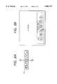
- FIGS. 9 and 10 are front views of the video tape recorder of this embodiment.
- FIG. 11 is a block diagram of this embodiment in a remote control condition for controlling the television set from the video tape recorder.
- FIG. 1 is a block diagram of an embodiment of the present invention showing a plurality of remote control electronic apparatus coupled to a network and an operation panel of a remote control unit is also shown.
- a television set (TV) 1, a video tape recorder (VTRa) 2, and a video tape recorder (VTRb) 3 are coupled to a communication cable 4.
- a remote control unit 5 is coupled to the television set 1 by an infrared signal ray, which can be coupled to the video tape recorder 2 or the video tape recorder 3 also.
- the television set 1 comprises a television hardware portion 11, a display (crt) 12, a light receiving portion 13 for receiving modulated infrared signal ray indicative of either of operations of respective keys on the operation panel from the remote control unit 5, a demodulation and a/d converting portion 14 for demodulating and a/d-converting the received infrared signal, a communication interface 15, having a video channel and a data channel, for interfacing the television set 1 with the communication cable 4, and a control circuit 24 including a central processing unit (TV-CPU) 16, a ROM (read-only memory) 17, and a RAM (random access memory) 18, and an I/O (input and output) port 19.
- TV-CPU central processing unit
- ROM read-only memory
- RAM random access memory
- the ROM 17 stores a local control program (TV-LCP) 20 for the television set 1, a remote control program (TV-RCP) 21 for the television set 1, a virtual language processing program 22, and a communication program 23.
- TV-LCP local control program
- TV-RCP remote control program
- the video tape recorder (VTRa) 2 comprises a VTR hardware portion 31 for effecting a plurality of functions such as, recording, reproducing, fast forwarding, and rewinding operations, etc., a liquid crystal display (LCD) 32, a liquid crystal display driver 33 for driving the LCD 32, a light receiving portion 34 for receiving modulated infrared signal ray indicative of either of operations of respective keys on the operation panel from the remote control unit 5, a demodulation and a/d converting portion 35 for demodulating and a/d-converting the received infrared signal, a communication interface 36, having a video channel and a data channel, for interfacing the video tape recorder 2 with the communication cable 4, and a control circuit including a central processing unit (VTRa-CPU) 37, a ROM 38, and a RAM 39, and an I/O (input and output) port 40.
- VTRa-CPU central processing unit
- ROM 38 read only memory
- RAM 39 random access memory
- the ROM 38 stores a local control program (VTRa-LCP) 41 for the video tape recorder 1, a remote control program (VTRa-RCP) for the video tape recorder 2, a virtual language processing program 43, and a communication program 44.
- VTRa-LCP local control program
- VTRa-RCP remote control program
- VTRa-RCP virtual language processing program
- FIG. 1 shows only the television set 1, the video tape recorders 2 and 3. However, it is possible to couple other remote control electronic apparatus having the similar circuit structure other than the inherent unit to remote control electronic apparatus, that is, the television hardware 11, the video tape recorder hardware portion.
- the remote control unit 5 which is different from the conventional type remote control units of television sets or video tape recorders, has a menu key 51, a cross shape cursor key 52, an execution key 53, and a device selection key 54 arranged as shown in FIG. 1.
- This remote control unit 5 can control any of the televisions set TV1, and the video tape recorders VTRa 2 and VTRb3.
- the light receiving portion 13 and the light transmitting portion 55 have directivities, so that each of the television set 1 and the video tape recorders 2 and 3 can be selectively operated.
- the remote control unit 5 may have a device selecting function to selectively control the television set 1 and video tape recorders 2 and 3, so that though these devices are adjacently located, they can be controlled selectively.
- Respective programs stored in the ROM 17 of the television set 1 and the ROM 38 of the video tape recorder 2 will be described, wherein there may be no distinguishing between the program of the television set and of the video tape recorder because there are common programs and it is important to control either of the remote control electronic apparatus itself or another remote control electronic apparatus.
- the local control programs of the television set 1 and the video tape recorder 2 are for controlling their own hardware portions (television hardware 11 and the video tape recorder hardware 31).
- each of the local control programs includes a program 1 for controlling the hardware of its own remote control electronic apparatus in response to an operation input of either of operation switches 56 provided to the operation panel on an enclosure of the remote control electronic apparatus, a program 2 for controlling the hardware portion of its own remote control electronic apparatus in response to an operation from its remote control unit 5 together with its remote control program through the input interface image, and a program 3 for, when there is a request for controlling the hardware portion of another remote control electronic apparatus from the remote control unit 5, loading the remote control program of another remote control electronic apparatus into the RAM of its own remote control electronic apparatus and providing a communication between the loaded remote control program and the local control program of another apparatus using the input interface image to control another remote control electronic apparatus through the network 4.
- a program 1 for controlling the hardware of its own remote control electronic apparatus in response to an operation input of either of operation switches 56 provided to the operation panel on an enclosure of the remote control electronic apparatus
- a program 2 for controlling the hardware portion of its own remote control electronic apparatus in response to an operation from its remote control unit 5 together with its remote control program through the
- This local control program is expressed by a language which can be directly executed by the its own central processing unit. Therefore, if the kinds of central processing units are different each other, the kinds of languages are different.
- the remote control program includes data of the operation input interface image of its own remote control electronic apparatus.
- FIG. 2A depicts a flow chart of this embodiment showing a television control operation with a guide by the operation input image on the display.
- FIG. 2B is an illustration of this embodiment showing the operation input image on the display of the television set 1.
- the remote control program includes data of the operation input image for selecting one of functions effected by its hardware portion.
- the remote control program controls the hardware portion of its own remote control electronic apparatus together with the local control program of its own remote control electronic apparatus through the remote control unit input operation using the operation input interface image as shown in FIGS.
- the remote control program when the remote control program is loaded in another remote control electronic apparatus, it displays the operation input interface image for selecting its own functions on the display of another remote control electronic apparatus and executes controlling the hardware portion of its own remote control electronic apparatus through the communication together with the local control program of its own remote control electronic apparatus.
- This program is expressed by a virtual language which commonly defined within the network to operate a virtual central processing unit. Therefore, the central processing units of respective remote control electronic apparatus cannot execute this directly, so that the remote control program is executed by each central processing unit through interpreting by the virtual language processing program.
- the virtual language processing program is for translating the remote control program expressed by the virtual language into a language which can be executed by the central processing unit of its own remote control electronic apparatus. More specifically, it has a translater for converting the remote control program expressed by the virtual language into native codes of the central processing unit of its own remote control electronic apparatus or an interpreter for translating commands in the remote control program word by word.
- the communication program is for controlling the communication with another remote control electronic apparatus through the communication interface and the communication cable 4.
- the communication program does not control the content of the communication data but only controls the address of its own remote control electronic apparatus and an address of the destination remote control electronic apparatus during the communication.
- the operator inputs address data and data of kinds of remote control electronic apparatus coupled to the communication cable 4 to the television set 1 through the remote control program 20 and the remote control program 21 using the remote control unit 5.
- the central processing unit 16 stores the address data and data of kinds of remote control electronic apparatus, as device data 71, in the RAM 18 through the remote control program 20 and the remote control program 21 using the remote control unit 5.
- the communication program 23 transmits the address data and data of kind of remote control electronic apparatus coupled to the communication cable 4.
- Other remote control electronic apparatus receive the address data and data of kind of remote control electronic apparatus and store the data.
- the central processing unit 16 When the television 1 is in a display mode in step st21, the central processing unit 16 is executing the local control program 20. In this condition, when an operator operates the menu key 51 on the remote control unit 5 with the light emitting portion 55 directing to the light receiving portion 13 in step st22, the central processing unit 16 of the television set 1 accesses to the remote control program 21 under the control of the local control program 20 and displays the operation input interface image which represents a graphical image of a control panel as shown in FIG. 2B on the display 12 through the translation by the virtual language processing portion in step st23.
- the operator shifts the cursor (pointer) to one of areas indicative of a channel number or a decrease or an increase of the sound volume on the operation input interface image and then, turns on the execution key to select the desired channel or an adjustment of the sound volume in step st24. Then, the operator depresses the menu key 51 to erase the operation input interface image on the display 12 in step st25.
- the operation input from the remote control unit 5 is received by the central processing unit 16 of the television set 1 under the control of the local control program 20 of the television set 1 and in response to each operation input, the central processing unit 16 controls the television hardware portion 11 with translating the remote control program 21 by the virtual language processing program 22.
- FIG. 3A depicts a flow chart of this embodiment showing the video input selection.
- FIG. 3B is an illustration of this embodiment showing the operation input image on the display 12 in the condition of step st34 shown in FIG. 3A.
- the operator displays the operation input image by depressing the menu key 51 in steps st32 and st33, shifts the cursor to a display area of VIDEO INPUT and then, depresses the execution key 53 in step st34 with directing the light emitting portion 55 to the light receiving portion 13 of the television set 1.
- FIG. 4A depicts a flow chart of this embodiment showing the device (remote control electronic apparatus) selection input and FIG. 4B is an illustration of this embodiment showing the operation input image for selecting one of devices (units).
- the central processing unit 16 of the television set 1 receives this command and displays the operation input image for selecting one of devices in step st42 in accordance with data of kinds of remote control electronic apparatus coupled to the communication cable 4.
- the data of kinds of remote control electronic apparatus provides the device table 59.
- the operator shifts the cursor 58 to the display area of the desired device as shown in FIG. 4B and depresses the execution key 53 in step st43, the central processing unit 16 enters a condition that it controls another remote control electronic apparatus.
- the operation input interface image returns to the image shown in FIG. 2B.
- FIG. 5A depicts of a flow chart of this embodiment showing the operation controlling another remote control electronic apparatus and FIG. 5B shows an illustration of this embodiment showing the operation input interface image for controlling the video tape recorder 2.
- the central processing unit 16 reads a control request command for the video tape recorder 2 from the local control program 20 of the television set 1 in accordance with the address data and data of kind of the remote control electronic apparatus stored in the RAM 18 and executes the communication program 23 to control the communication interface 15 to transmits the control request command to the video tape recorder 2 through the communication cable 4.
- the central processing unit 37 of the video tape recorder 2 receiving the control request command, reads the remote control program 42 from the ROM 38, executes the communication program 44, and transmits the read remote control program 42 to the television set 1 through the communication interface 36 and the communication cable 4 under the control of the local control program 41 as shown by the chain line 60 in FIG. 1.
- the central processing unit 16 of the television set 1 receives the remote control program 42 transmitted from the video tape recorder through the interface 15 and stores the remote control program 42 in the RAM 18 under the control of the local control program 20 in step st51.
- the central processing unit 16 executes the remote control program stored in the RAM 18 with commands and data in the remote control program 42' translated by the virtual language processing program under the control of the local control program 20.
- the central processing unit 16 cannot execute the remote control program 42 directly, so that the central processing unit 16 translates the commands and data of the remote control program 42 by the virtual language processing program 22 and executes the translated commands.
- the central processing unit 16 displays the operation input interface image data as shown in FIG. 5B in step st52 under the control of the local control program 20. Then, the central processing unit 16 receives an operation input from the remote control unit 5.
- the operation input interface image of the video tape recorder 2 includes icons representing operations of reproduction, stopping, fast-forwarding, rewinding, and icons for controlling the television set 1 and also provides the status information to the operator as shown in FIG. 5B.
- FIG. 6A depicts a flow chart of this embodiment showing a command operation of the reproduction.
- FIG. 6B is an illustration of this embodiment showing the operation input interface image for the reproduction operation.
- the reproduction command is received by the remote control program (VTRa-RCP) 42' in the RAM 18 via the local control program (TV-LCP) 20 and transmitted to the video tape recorder 2 through the communication cable 4 and the communication interfaces 15 and 36 of which link conditions are kept by the communication programs 21 and 44.
- VTRa-RCP remote control program
- TV-LCP local control program
- the central processing unit (VTRa-CPU) 37 of the video tape recorder 2 receiving the reproduction command by the communication interface 36 and the communication program 44 executes the local control program (VTRa-LCP) 41 to move its operation mode to the reproduction mode by controlling the video tape hard ware portion 31. Then, the central processing unit 37 of the video tape recorder 2 transmits the video signal derived from the reproduction of a video tape to the television set 1 through the communication interface 36 and the communication cable 4 and the television set 1 receives the reproduced video signal and displays the reproduced video image on the display 12. Moreover, the video tape recorder 2 generates and transmits status information indicative of an operation status of the video tape recorder 2 to the television set 1 through the communication cable 4.
- the central processing unit 16 of the television set 1 receives the status information using the local control program 20 of the television set 1 and executes the remote control program (VTRa-RCP) 42' in the RAM 18, thereby displaying the status information at a predetermined area at the operation input interface image on the display 12.
- VTRa-RCP remote control program
- FIG. 7A depicts a flow chart of this embodiment showing a remote control operation of the video tape recorder by the television set 1.
- FIG. 7B is an illustration of this embodiment showing the operation input interface image with the reproduction image from the video tape recorder 2.
- this link condition between the television set 1 and the video tape recorder 2 is kept, so that a further controlling the video tape recorder 2 during reproduction can be received by the television set 1 and the video tape recorder 2. That is, as shown, the operator can display the operation input interface image by operating the menu key 51 on the remote control unit 5 as necessary in step st71 and can other desired controlling is provided by operating the keys on the remote control unit 5 through the operation input interface image in step st76. Moreover, the operation input interface image can be erased from the screen of the display 12.
- the remote control program (VTRa-RCP) 42' is originally stored in the video tape recorder (VTRa) 2 and the actual controlling is effected by the coactive operation by the remote control program (VTRa-RCP) 42' in the RAM 18 of the television set 1 transmitted from the video tape recorder and the local control program (VTRa-LCP) 41 in the ROM 38 of the video tape recorder 2 through the communication line 4 using the virtual language processing program.
- the actual command to the hardware portion 31 of the video tape recorder 2 such as reproduction and recording, can be independently defined within the video tape recorder 2, that is, it is unnecessary to uniquely define command codes with command codes managed among respective remote control electronic apparatus coupled to the network.
- FIG. 8 is an illustration of this embodiment showing a format of data transmitted.
- the data transmitted between remote control electronic apparatus in the network has the format as shown in FIG. 8, that is, the data includes data of a destination address 81, a source address 82, a kind of data 83, a data length 84, and data body 85 to be communicated.
- the data of the destination address and the source address 82 are managed and generated by the interfaces 15, 36, etc. and the communication programs and indicate the source of the remote control electronic apparatus transmitting the data body 85 and the destination remote control electronic apparatus which should receive the transmitted data body 85.
- the kind of data is a flag indicating either of the remote control data, the device data, or the other data.
- the communication interface of the remote control electronic apparatus receiving the transmitted data acquires the transmitted data and stores it and the data of the source of the remote control electronic apparatus transmitting the data if the data of destination address 81 is directed to the remote control electronic apparatus. Then, if the kind of data is a remote control program of the source remote control electronic apparatus, the central processing unit stores the data as the remote control program of the source remote control electronic apparatus In the RAM. Then, the remote controlling between the remote control electronic apparatus mentioned above is effected through translating the remote control program with the virtual language translating processing program.
- the kind of data is not the remote control program (RCP), that is, if the kind of data is a control command, the data is forwarded to the local control program to executes the control command and if the kind of dat is status information, it is forwarded to the remote control program to display the operation input interface image as shown in FIG. 5B.
- RCP remote control program
- the central processing unit stores the device data in the RAM.
- the RAM may be provided with a battery backup or comprises an EEPROM (electrically erasable/programmable read-only memory).
- FIGS. 9 and 10 are front views of the video tape recorder of this embodiment.
- the video tape recorder 2 When the operator depresses the device selection key 54 with the light emitting portion 55 of the remote control unit 5 directed to the video tape recorder 2, the video tape recorder 2 displays a table of devices to be controlled on the LCD 32 in accordance with the device data 70 as shown in FIG. 9. The operator operates the cursor key 52 to move the cursor to a marker of the television set 1 in the table and depresses the execution key 53 of the remote control unit 5.
- the central processing unit 37 of the video tape recorder 2 generates a control request command of the television set 1 in accordance with the device data 70 under the control of the local control program (VTRa-LCP) 41 and controls the communication interface 36 by executing the communication program 44 to transmit the control request command to the television set 1 through the communication cable 4.
- VTRa-LCP local control program
- FIG. 11 is a block diagram of this embodiment in a remote control condition for controlling the television set from the video tape recorder 2.
- the central processing unit 16 of the television set 1 receiving the control request command, reads the remote control program 21 from the ROM 17, executes the communication program 23, and transmits the read remote control program 21 to the video tape recorder 2 through the communication interface 15 and the communication cable 4 under the control of the local control program 20 as shown by the chain line 61 in FIG. 11.
- the central processing unit 37 of the video tape recorder 2 receives the remote control program 21 transmitted from the television set 1 through the communication interface 36 and stores the remote control program 21 as a remote control program 21' in the RAM 39 under the control of the local control program 41.
- the remote control program 21 is stored in the RAM 39 as similar to the remote control program 42 is stored in the RAM 18 in step s51 as mentioned earlier.
- the central processing unit 37 executes the remote control program 21' stored in the RAM 39 with commands of the remote control program 21' translated by the virtual language processing program 43 under the control of the local control program 41.
- the central processing unit 37 displays the operation input interface image as shown in FIG. 10 under the control of the local control program 41. Then, the central processing unit 37 receives commands from the remote control unit 5.
- This operation input interface image shown in FIG. 10 is substantially the same as that shown in FIG. 2B. However, because the size of the LCD 32 is small, it is necessary to change the arrangement of the icons to display all necessary icons. Actually, each of the remote control programs 21, 21', 42, and 42' stores a plurality sets of data of the operation input interface images having different arrangements. The local control program 41 selects and displays one of operation input interface images suitable for the LCD 32.
- the operation input interface image of the video tape recorder 2 includes icons regarding operations of the television set 1, and an icon for controlling the video tape recorder 2 itself. Then, as similar to the case of remote-controlling the video tape recorder 2 by the television set 1, the remote-controlling the television set 1 is performed through the coactive operation between the local control program (VTRa-LCP) 41 and remote control program (TV-RCP) 21'.
- VTRa-LCP local control program
- TV-RCP remote control program
- a plurality of television sets are coupled to the communication cable 4 and the communication cable can only transmits one channel of video signal, only one television set is allowed to control a video tape recorder.
- Other television sets are inhibited to control the video tape recorder by transmitting a control inhibit command from the video tape recorder in response to a further control request command and only allowed to monitor the same reproduced image.
- the remote control operation between two remote control electronic apparatus is provided by the remote control program expressed by a virtual language which is common in the network and is executed by the virtual language processing program with the remote control program is transmitted to the remote control electronic apparatus remote-controlling the other remote control electronic apparatus, the command codes for controlling the hardware portion of each remote control electronic apparatus can be independently defined and it is easy to add a new remote control electronic apparatus to the network.
- the operator inputs address data and data of kinds of remote control electronic apparatus coupled to the communication cable 4 to the television set 1 through the remote control program 20 and the remote control program 21 using the remote control unit 5.
- the central processing unit 16 stores the address data and data of kinds of remote control electronic apparatus, as device data 71, in the RAM 18 through the remote control program 20 and the remote control program 21 using the remote control unit 5 and transmits the device data to other electronic apparatus.
- the central processing unit 16 receives the command of the device selection key 54 in step st42, the central processing unit 16 generates a global device data request command directing to all other electronic apparatus coupled to the communication cable 4.
- Each of the central processing units of other electronic apparatus receiving the global device data request command generates its device data stored in its local control program and returns its device data to the central processing unit 16 under control of its local control program.
- the central processing unit 16 receiving device data from other electronic apparatus generates the device table 59 as shown in FIG. 4B.
- Other structure and operation are similar as mentioned earlier.
Abstract
A method of controlling remote control electronic apparatus coupled to a network and a remote control electronic apparatus to be coupled to a network are disclosed. Each remote control electronic apparatus has a CPU and a ROM including a local control program expressed by an independent language which is interpretable by the CPU, a remote control program expressed by a virtual language, a virtual language processing program for processing the virtual language to make it interpretable by the CPU. When one remote control electronic apparatus is required to control another remote control electronic apparatus coupled to the network, the remote control electronic apparatus requests to transmit the remote control program of another remote control apparatus. The remote control electronic apparatus receiving the transmitted remote control program of another remote control apparatus generates an operation command signal using the received remote control program through the virtual language processing program and transmits the operation command signal to another remote control apparatus which is actually operated by the local control program existing in another remote control apparatus according to the operation command signal.
Description
1. Field of the Invention
This invention relates to a method of controlling remote control electronic apparatus coupled to a network and to a remote control electronic apparatus to be coupled to a network.
2. Description of the Prior Art
A method of controlling remote control electronic apparatus coupled to a network is known. For example, the AV (Audio Visual) compu-link system including television sets and video tape recorders or the like are coupled through a communication cable is known. In this system, command codes for power on and off, changing the channel, reproducing, recording, changing a volume, or the like are uniquely assigned in advance among remote control electronic apparatus connected to the communication cable.
The remote controlling is provided by transmitting the command code from one apparatus to another through the communication line.
The aim of the present invention is to provide an improved method of controlling remote control electronic apparatus coupled to a network and to an improved remote control electronic apparatus to be coupled to a network.
According to the present invention, a method of controlling a plurality of electronic apparatus coupled to a network is provided, each electronic apparatus having a microprocessor, a display, at least a memory, a remote control unit communication unit, and a functional unit effecting a plurality of functions, the method comprising the steps of:
providing a local control program, a remote control program, and a virtual language processing program in at least a memory of each electronic apparatus, the local control program of each electronic apparatus being provided to be executed by the microprocessor to control each electronic apparatus in response to an input operation signal from a remote control unit in cooperation with the remote control program through the remote control unit communication unit when the input operation signal is indicative of controlling the functional unit of each electronic apparatus itself and to request another electronic apparatus to transmit the remote control program of another electric apparatus through the network and receive the remote control program of another electronic apparatus when the input operation signal is indicative of controlling the functional unit of another electronic apparatus, each local control program being expressed by each language interpretable by the microprocessor of each electronic apparatus, the remote control program of each electronic apparatus being provided to display an operation inputting interface image for selecting one of the plurality of functions of each electronic apparatus in cooperation with the local control program of each electronic apparatus, receive the input operation signal indicative of selecting one of the plurality of functions from the remote control unit, and control the functional unit of each electronic apparatus together with the local control program of each electronic apparatus in accordance with the input operation signal indicative of selecting one of functions, the remote control program including command and data which are expressed by a virtual language and being executed by the microprocessor through processing by the virtual language processing program, the virtual language being common in the network; and
when the microprocessor of one of the electronic apparatus receives the input operation signal indicative of a request for controlling another electronic apparatus from the remote control unit, executing the local control program of one of electronic apparatus to request another electronic apparatus to transmit the remote control program of another electronic apparatus, receiving and storing the remote control program of another electronic apparatus in at least a memory and executing the remote control program from another electronic apparatus in the memory, displaying the operation inputting interface image on the display of one of the electric apparatus, receiving and transmitting the input operation signal indicative of selecting one of functions of another electronic apparatus from the remote control unit to the local control program of another electronic apparatus through the network to effect one of the functions of another electronic apparatus.
According to the present invention, an electronic apparatus to be coupled to another electronic apparatus through a network is provided which comprises:
a microprocessor, a display, a RAM, a ROM, a remote control unit communication unit, a network interface unit, and a functional unit for effecting a plurality of functions,
wherein the ROM stores a local control program independently interpretable for the microprocessor, a remote control program including operation input interface image data for selecting one of the plurality of functions, and a virtual language processing program for interpreting the remote control program for the microprocessor, the microprocessor receives an input operation signal from a remote control unit via the remote control unit communication unit in cooperation with the local control program and remote control program,
when the microprocessor receives the input operation signal indicative of a request for controlling another electronic apparatus from the remote control unit, in cooperation with the local control program of the electronic apparatus, the microprocessor requests another electronic apparatus to transmit the remote control program of another electronic apparatus through the network, receives and stores the remote control program of another electronic apparatus in the RAM, the microprocessor executes the remote control program from another electronic apparatus in the RAM using the virtual language processing program, displays the operation inputting interface image data of another electronic apparatus on the display, and
receives and transmits the input operation signal indicative of selecting one of plurality of functions of another electronic apparatus from the remote control unit to another electronic apparatus through the network and the network interface unit to effect one of the functions of another electronic apparatus through the local control program in another electronic apparatus.
The object and features of the present invention will become more readily apparent from the following detailed description taken in conjunction with the accompanying drawings in which:
FIG. 1 is a block diagram of an embodiment of the present invention showing a plurality of remote control electronic apparatus coupled to a network;
FIG. 2A depicts a flow chart of this embodiment showing a television control operation with a guide by an operation input interface image on a display;
FIG. 2B is an illustration of this embodiment showing an operation input interface image on the display of a television set;
FIG. 3A depicts a flow chart of this embodiment showing a video input selection operation;
FIG. 3B is an illustration of this embodiment showing an operation input interface image on the display;
FIG. 4A depicts a flow chart of this embodiment showing a device selection input operation;
FIG. 4B is an illustration of this embodiment showing an operation input interface image for selecting one of devices;
FIG. 5A depicts of a flow chart of this embodiment showing an operation controlling another electronic apparatus;
FIG. 5B shows an illustration of this embodiment showing an operation input interface image for controlling a video tape recorder;
FIG. 6A depicts a flow chart of this embodiment showing a command operation of reproduction;
FIG. 6B is an illustration of this embodiment showing an operation input interface image for a reproduction operation;
FIG. 7A depicts a flow chart of this embodiment showing a remote control operation of the video tape recorder by the television set;
FIG. 7B is an illustration of this embodiment showing an operation input interface image with a reproduction image;
FIG. 8 is an illustration of this embodiment showing a format of data;
FIGS. 9 and 10 are front views of the video tape recorder of this embodiment; and
FIG. 11 is a block diagram of this embodiment in a remote control condition for controlling the television set from the video tape recorder.
The same or corresponding elements or parts are designated with like references throughout the drawings.
FIG. 1 is a block diagram of an embodiment of the present invention showing a plurality of remote control electronic apparatus coupled to a network and an operation panel of a remote control unit is also shown.
A television set (TV) 1, a video tape recorder (VTRa) 2, and a video tape recorder (VTRb) 3 are coupled to a communication cable 4. A remote control unit 5 is coupled to the television set 1 by an infrared signal ray, which can be coupled to the video tape recorder 2 or the video tape recorder 3 also.
The television set 1 comprises a television hardware portion 11, a display (crt) 12, a light receiving portion 13 for receiving modulated infrared signal ray indicative of either of operations of respective keys on the operation panel from the remote control unit 5, a demodulation and a/d converting portion 14 for demodulating and a/d-converting the received infrared signal, a communication interface 15, having a video channel and a data channel, for interfacing the television set 1 with the communication cable 4, and a control circuit 24 including a central processing unit (TV-CPU) 16, a ROM (read-only memory) 17, and a RAM (random access memory) 18, and an I/O (input and output) port 19.
The ROM 17 stores a local control program (TV-LCP) 20 for the television set 1, a remote control program (TV-RCP) 21 for the television set 1, a virtual language processing program 22, and a communication program 23.
The video tape recorder (VTRa) 2 comprises a VTR hardware portion 31 for effecting a plurality of functions such as, recording, reproducing, fast forwarding, and rewinding operations, etc., a liquid crystal display (LCD) 32, a liquid crystal display driver 33 for driving the LCD 32, a light receiving portion 34 for receiving modulated infrared signal ray indicative of either of operations of respective keys on the operation panel from the remote control unit 5, a demodulation and a/d converting portion 35 for demodulating and a/d-converting the received infrared signal, a communication interface 36, having a video channel and a data channel, for interfacing the video tape recorder 2 with the communication cable 4, and a control circuit including a central processing unit (VTRa-CPU) 37, a ROM 38, and a RAM 39, and an I/O (input and output) port 40.
The ROM 38 stores a local control program (VTRa-LCP) 41 for the video tape recorder 1, a remote control program (VTRa-RCP) for the video tape recorder 2, a virtual language processing program 43, and a communication program 44.
FIG. 1 shows only the television set 1, the video tape recorders 2 and 3. However, it is possible to couple other remote control electronic apparatus having the similar circuit structure other than the inherent unit to remote control electronic apparatus, that is, the television hardware 11, the video tape recorder hardware portion.
Moreover, the remote control unit 5, which is different from the conventional type remote control units of television sets or video tape recorders, has a menu key 51, a cross shape cursor key 52, an execution key 53, and a device selection key 54 arranged as shown in FIG. 1. This remote control unit 5 can control any of the televisions set TV1, and the video tape recorders VTRa 2 and VTRb3. However, the light receiving portion 13 and the light transmitting portion 55 have directivities, so that each of the television set 1 and the video tape recorders 2 and 3 can be selectively operated. Further, the remote control unit 5 may have a device selecting function to selectively control the television set 1 and video tape recorders 2 and 3, so that though these devices are adjacently located, they can be controlled selectively.
Respective programs stored in the ROM 17 of the television set 1 and the ROM 38 of the video tape recorder 2 will be described, wherein there may be no distinguishing between the program of the television set and of the video tape recorder because there are common programs and it is important to control either of the remote control electronic apparatus itself or another remote control electronic apparatus.
(1) Local Control Programs (TV-LCP 20, VTRa-LCP41)
The local control programs of the television set 1 and the video tape recorder 2 are for controlling their own hardware portions (television hardware 11 and the video tape recorder hardware 31).
More specifically, each of the local control programs includes a program 1 for controlling the hardware of its own remote control electronic apparatus in response to an operation input of either of operation switches 56 provided to the operation panel on an enclosure of the remote control electronic apparatus, a program 2 for controlling the hardware portion of its own remote control electronic apparatus in response to an operation from its remote control unit 5 together with its remote control program through the input interface image, and a program 3 for, when there is a request for controlling the hardware portion of another remote control electronic apparatus from the remote control unit 5, loading the remote control program of another remote control electronic apparatus into the RAM of its own remote control electronic apparatus and providing a communication between the loaded remote control program and the local control program of another apparatus using the input interface image to control another remote control electronic apparatus through the network 4.
This local control program is expressed by a language which can be directly executed by the its own central processing unit. Therefore, if the kinds of central processing units are different each other, the kinds of languages are different.
(2) Remote Control Programs (TV-RCP21, VTRa-RCP42)
The remote control program includes data of the operation input interface image of its own remote control electronic apparatus. FIG. 2A depicts a flow chart of this embodiment showing a television control operation with a guide by the operation input image on the display. FIG. 2B is an illustration of this embodiment showing the operation input image on the display of the television set 1. The remote control program includes data of the operation input image for selecting one of functions effected by its hardware portion. The remote control program controls the hardware portion of its own remote control electronic apparatus together with the local control program of its own remote control electronic apparatus through the remote control unit input operation using the operation input interface image as shown in FIGS. 2A and 2B, and when the remote control program is loaded in another remote control electronic apparatus, it displays the operation input interface image for selecting its own functions on the display of another remote control electronic apparatus and executes controlling the hardware portion of its own remote control electronic apparatus through the communication together with the local control program of its own remote control electronic apparatus.
This program is expressed by a virtual language which commonly defined within the network to operate a virtual central processing unit. Therefore, the central processing units of respective remote control electronic apparatus cannot execute this directly, so that the remote control program is executed by each central processing unit through interpreting by the virtual language processing program.
(3) Virtual Language Processing Programs 22, 43
The virtual language processing program is for translating the remote control program expressed by the virtual language into a language which can be executed by the central processing unit of its own remote control electronic apparatus. More specifically, it has a translater for converting the remote control program expressed by the virtual language into native codes of the central processing unit of its own remote control electronic apparatus or an interpreter for translating commands in the remote control program word by word.
(4) The Communication Programs 23 and 44
The communication program is for controlling the communication with another remote control electronic apparatus through the communication interface and the communication cable 4.
The communication program does not control the content of the communication data but only controls the address of its own remote control electronic apparatus and an address of the destination remote control electronic apparatus during the communication.
Then, operations will be described in the case the television 1 is controlled by the remote control unit 5 and then, the case that the video tape recorder 2 is controlled via the television 1. It is assumed that all units of this system have been turned on and the system has been operated.
More specifically, when the system is started up, the operator inputs address data and data of kinds of remote control electronic apparatus coupled to the communication cable 4 to the television set 1 through the remote control program 20 and the remote control program 21 using the remote control unit 5. The central processing unit 16 stores the address data and data of kinds of remote control electronic apparatus, as device data 71, in the RAM 18 through the remote control program 20 and the remote control program 21 using the remote control unit 5. The communication program 23 transmits the address data and data of kind of remote control electronic apparatus coupled to the communication cable 4. Other remote control electronic apparatus receive the address data and data of kind of remote control electronic apparatus and store the data.
When the television 1 is in a display mode in step st21, the central processing unit 16 is executing the local control program 20. In this condition, when an operator operates the menu key 51 on the remote control unit 5 with the light emitting portion 55 directing to the light receiving portion 13 in step st22, the central processing unit 16 of the television set 1 accesses to the remote control program 21 under the control of the local control program 20 and displays the operation input interface image which represents a graphical image of a control panel as shown in FIG. 2B on the display 12 through the translation by the virtual language processing portion in step st23.
Then, the operator shifts the cursor (pointer) to one of areas indicative of a channel number or a decrease or an increase of the sound volume on the operation input interface image and then, turns on the execution key to select the desired channel or an adjustment of the sound volume in step st24. Then, the operator depresses the menu key 51 to erase the operation input interface image on the display 12 in step st25.
During this operation, the operation input from the remote control unit 5 is received by the central processing unit 16 of the television set 1 under the control of the local control program 20 of the television set 1 and in response to each operation input, the central processing unit 16 controls the television hardware portion 11 with translating the remote control program 21 by the virtual language processing program 22.
If the operator desires to watch a program from the video tape recorder 2, the operator can select a video input mode. FIG. 3A depicts a flow chart of this embodiment showing the video input selection. FIG. 3B is an illustration of this embodiment showing the operation input image on the display 12 in the condition of step st34 shown in FIG. 3A. The operator displays the operation input image by depressing the menu key 51 in steps st32 and st33, shifts the cursor to a display area of VIDEO INPUT and then, depresses the execution key 53 in step st34 with directing the light emitting portion 55 to the light receiving portion 13 of the television set 1.
Then, the central processing unit 16 changes the mode from the television display mode to the video input mode. FIG. 4A depicts a flow chart of this embodiment showing the device (remote control electronic apparatus) selection input and FIG. 4B is an illustration of this embodiment showing the operation input image for selecting one of devices (units).
When the operator depresses the device selection key 54 of the remote control unit 5 in step st41, the central processing unit 16 of the television set 1 receives this command and displays the operation input image for selecting one of devices in step st42 in accordance with data of kinds of remote control electronic apparatus coupled to the communication cable 4. The data of kinds of remote control electronic apparatus provides the device table 59. The operator shifts the cursor 58 to the display area of the desired device as shown in FIG. 4B and depresses the execution key 53 in step st43, the central processing unit 16 enters a condition that it controls another remote control electronic apparatus. However, if the operator selects the television set 1 from the selection menu shown in FIG. 4B, the operation input interface image returns to the image shown in FIG. 2B.
FIG. 5A depicts of a flow chart of this embodiment showing the operation controlling another remote control electronic apparatus and FIG. 5B shows an illustration of this embodiment showing the operation input interface image for controlling the video tape recorder 2.
As mentioned, when the operator selects the video tape recorder 2, the central processing unit 16 reads a control request command for the video tape recorder 2 from the local control program 20 of the television set 1 in accordance with the address data and data of kind of the remote control electronic apparatus stored in the RAM 18 and executes the communication program 23 to control the communication interface 15 to transmits the control request command to the video tape recorder 2 through the communication cable 4.
The central processing unit 37 of the video tape recorder 2 receiving the control request command, reads the remote control program 42 from the ROM 38, executes the communication program 44, and transmits the read remote control program 42 to the television set 1 through the communication interface 36 and the communication cable 4 under the control of the local control program 41 as shown by the chain line 60 in FIG. 1.
The central processing unit 16 of the television set 1 receives the remote control program 42 transmitted from the video tape recorder through the interface 15 and stores the remote control program 42 in the RAM 18 under the control of the local control program 20 in step st51.
Then, the central processing unit 16 executes the remote control program stored in the RAM 18 with commands and data in the remote control program 42' translated by the virtual language processing program under the control of the local control program 20.
That is, because the remote control program is expressed by the virtual language, the central processing unit 16 cannot execute the remote control program 42 directly, so that the central processing unit 16 translates the commands and data of the remote control program 42 by the virtual language processing program 22 and executes the translated commands.
The central processing unit 16 displays the operation input interface image data as shown in FIG. 5B in step st52 under the control of the local control program 20. Then, the central processing unit 16 receives an operation input from the remote control unit 5.
The operation input interface image of the video tape recorder 2 includes icons representing operations of reproduction, stopping, fast-forwarding, rewinding, and icons for controlling the television set 1 and also provides the status information to the operator as shown in FIG. 5B.
FIG. 6A depicts a flow chart of this embodiment showing a command operation of the reproduction. FIG. 6B is an illustration of this embodiment showing the operation input interface image for the reproduction operation.
When the operator selects the reproduction mode as shown in FIG. 6B by operating the cursor key 52 and depressing the execution key 53 in the condition that the operation input interface image of the video tape recorder 2 is displayed, the reproduction command is received by the remote control program (VTRa-RCP) 42' in the RAM 18 via the local control program (TV-LCP) 20 and transmitted to the video tape recorder 2 through the communication cable 4 and the communication interfaces 15 and 36 of which link conditions are kept by the communication programs 21 and 44.
The central processing unit (VTRa-CPU) 37 of the video tape recorder 2 receiving the reproduction command by the communication interface 36 and the communication program 44 executes the local control program (VTRa-LCP) 41 to move its operation mode to the reproduction mode by controlling the video tape hard ware portion 31. Then, the central processing unit 37 of the video tape recorder 2 transmits the video signal derived from the reproduction of a video tape to the television set 1 through the communication interface 36 and the communication cable 4 and the television set 1 receives the reproduced video signal and displays the reproduced video image on the display 12. Moreover, the video tape recorder 2 generates and transmits status information indicative of an operation status of the video tape recorder 2 to the television set 1 through the communication cable 4. The central processing unit 16 of the television set 1 receives the status information using the local control program 20 of the television set 1 and executes the remote control program (VTRa-RCP) 42' in the RAM 18, thereby displaying the status information at a predetermined area at the operation input interface image on the display 12.
FIG. 7A depicts a flow chart of this embodiment showing a remote control operation of the video tape recorder by the television set 1. FIG. 7B is an illustration of this embodiment showing the operation input interface image with the reproduction image from the video tape recorder 2.
During the reproduction mode, this link condition between the television set 1 and the video tape recorder 2 is kept, so that a further controlling the video tape recorder 2 during reproduction can be received by the television set 1 and the video tape recorder 2. That is, as shown, the operator can display the operation input interface image by operating the menu key 51 on the remote control unit 5 as necessary in step st71 and can other desired controlling is provided by operating the keys on the remote control unit 5 through the operation input interface image in step st76. Moreover, the operation input interface image can be erased from the screen of the display 12.
In the above-mentioned description, it is important that the remote control program (VTRa-RCP) 42' is originally stored in the video tape recorder (VTRa) 2 and the actual controlling is effected by the coactive operation by the remote control program (VTRa-RCP) 42' in the RAM 18 of the television set 1 transmitted from the video tape recorder and the local control program (VTRa-LCP) 41 in the ROM 38 of the video tape recorder 2 through the communication line 4 using the virtual language processing program. Thus, the actual command to the hardware portion 31 of the video tape recorder 2, such as reproduction and recording, can be independently defined within the video tape recorder 2, that is, it is unnecessary to uniquely define command codes with command codes managed among respective remote control electronic apparatus coupled to the network.
FIG. 8 is an illustration of this embodiment showing a format of data transmitted.
The data transmitted between remote control electronic apparatus in the network has the format as shown in FIG. 8, that is, the data includes data of a destination address 81, a source address 82, a kind of data 83, a data length 84, and data body 85 to be communicated. The data of the destination address and the source address 82 are managed and generated by the interfaces 15, 36, etc. and the communication programs and indicate the source of the remote control electronic apparatus transmitting the data body 85 and the destination remote control electronic apparatus which should receive the transmitted data body 85. The kind of data is a flag indicating either of the remote control data, the device data, or the other data.
In the remote controlling between the remote control electronic apparatus, the communication interface of the remote control electronic apparatus receiving the transmitted data acquires the transmitted data and stores it and the data of the source of the remote control electronic apparatus transmitting the data if the data of destination address 81 is directed to the remote control electronic apparatus. Then, if the kind of data is a remote control program of the source remote control electronic apparatus, the central processing unit stores the data as the remote control program of the source remote control electronic apparatus In the RAM. Then, the remote controlling between the remote control electronic apparatus mentioned above is effected through translating the remote control program with the virtual language translating processing program. If the kind of data is not the remote control program (RCP), that is, if the kind of data is a control command, the data is forwarded to the local control program to executes the control command and if the kind of dat is status information, it is forwarded to the remote control program to display the operation input interface image as shown in FIG. 5B.
If the transmitted data is the device data of all remote control electronic apparatus coupled to the communication cable 4, the central processing unit stores the device data in the RAM. The RAM may be provided with a battery backup or comprises an EEPROM (electrically erasable/programmable read-only memory).
An operation of controlling the television set 1 on the side of the video tape recorder 2 will be described.
FIGS. 9 and 10 are front views of the video tape recorder of this embodiment.
When the operator depresses the device selection key 54 with the light emitting portion 55 of the remote control unit 5 directed to the video tape recorder 2, the video tape recorder 2 displays a table of devices to be controlled on the LCD 32 in accordance with the device data 70 as shown in FIG. 9. The operator operates the cursor key 52 to move the cursor to a marker of the television set 1 in the table and depresses the execution key 53 of the remote control unit 5.
In response to this, the central processing unit 37 of the video tape recorder 2 generates a control request command of the television set 1 in accordance with the device data 70 under the control of the local control program (VTRa-LCP) 41 and controls the communication interface 36 by executing the communication program 44 to transmit the control request command to the television set 1 through the communication cable 4.
FIG. 11 is a block diagram of this embodiment in a remote control condition for controlling the television set from the video tape recorder 2.
The central processing unit 16 of the television set 1 receiving the control request command, reads the remote control program 21 from the ROM 17, executes the communication program 23, and transmits the read remote control program 21 to the video tape recorder 2 through the communication interface 15 and the communication cable 4 under the control of the local control program 20 as shown by the chain line 61 in FIG. 11.
The central processing unit 37 of the video tape recorder 2 receives the remote control program 21 transmitted from the television set 1 through the communication interface 36 and stores the remote control program 21 as a remote control program 21' in the RAM 39 under the control of the local control program 41.
As mentioned, though the relation between the devices are inverse, the remote control program 21 is stored in the RAM 39 as similar to the remote control program 42 is stored in the RAM 18 in step s51 as mentioned earlier.
Then, the central processing unit 37 executes the remote control program 21' stored in the RAM 39 with commands of the remote control program 21' translated by the virtual language processing program 43 under the control of the local control program 41.
The central processing unit 37 displays the operation input interface image as shown in FIG. 10 under the control of the local control program 41. Then, the central processing unit 37 receives commands from the remote control unit 5.
This operation input interface image shown in FIG. 10 is substantially the same as that shown in FIG. 2B. However, because the size of the LCD 32 is small, it is necessary to change the arrangement of the icons to display all necessary icons. Actually, each of the remote control programs 21, 21', 42, and 42' stores a plurality sets of data of the operation input interface images having different arrangements. The local control program 41 selects and displays one of operation input interface images suitable for the LCD 32.
The operation input interface image of the video tape recorder 2 includes icons regarding operations of the television set 1, and an icon for controlling the video tape recorder 2 itself. Then, as similar to the case of remote-controlling the video tape recorder 2 by the television set 1, the remote-controlling the television set 1 is performed through the coactive operation between the local control program (VTRa-LCP) 41 and remote control program (TV-RCP) 21'.
Therefore, in this operation, it is also unnecessary to uniquely define command codes with command codes managed among respective remote control electronic apparatus coupled to the network.
If a plurality of television sets are coupled to the communication cable 4 and the communication cable can only transmits one channel of video signal, only one television set is allowed to control a video tape recorder. Other television sets are inhibited to control the video tape recorder by transmitting a control inhibit command from the video tape recorder in response to a further control request command and only allowed to monitor the same reproduced image.
As mentioned, because the remote control operation between two remote control electronic apparatus is provided by the remote control program expressed by a virtual language which is common in the network and is executed by the virtual language processing program with the remote control program is transmitted to the remote control electronic apparatus remote-controlling the other remote control electronic apparatus, the command codes for controlling the hardware portion of each remote control electronic apparatus can be independently defined and it is easy to add a new remote control electronic apparatus to the network.
A modification will be described.
As mentioned above, when the system is started up, the operator inputs address data and data of kinds of remote control electronic apparatus coupled to the communication cable 4 to the television set 1 through the remote control program 20 and the remote control program 21 using the remote control unit 5. The central processing unit 16 stores the address data and data of kinds of remote control electronic apparatus, as device data 71, in the RAM 18 through the remote control program 20 and the remote control program 21 using the remote control unit 5 and transmits the device data to other electronic apparatus. However, in the modification, when the central processing unit 16 receives the command of the device selection key 54 in step st42, the central processing unit 16 generates a global device data request command directing to all other electronic apparatus coupled to the communication cable 4. Each of the central processing units of other electronic apparatus receiving the global device data request command generates its device data stored in its local control program and returns its device data to the central processing unit 16 under control of its local control program. The central processing unit 16 receiving device data from other electronic apparatus generates the device table 59 as shown in FIG. 4B. Other structure and operation are similar as mentioned earlier.
Claims (2)
1. A method of controlling a plurality of electronic apparatus coupled to a network, each electronic apparatus having a microprocessor, a display, at least a memory, a remote control unit communication unit, and a functional unit effecting a plurality of functions, comprising the steps of:
providing a local control program, a remote control program, and a virtual language processing program in said at least a memory of each electronic apparatus, said local control program of each electronic apparatus being provided to be executed by said microprocessor to control each electronic apparatus in response to an input operation signal from a remote control unit in cooperation with said remote control program through said remote control unit communication unit when said input operation signal is indicative of controlling said functional unit of said each electronic apparatus itself and to request another electronic apparatus to transmit said remote control program of said another electric apparatus through said network and receive said remote control program of said another electronic apparatus when said input operation signal is indicative of controlling said functional unit of said another electronic apparatus, said each local control program being expressed by each language interpretable by said microprocessor of each electronic apparatus, said remote control program of each electronic apparatus being provided to display an operation inputting interface image for selecting one of said plurality of functions of said each electronic apparatus in cooperation with said local control program of said each electronic apparatus, receive said input operation signal indicative of selecting said one of said plurality of functions from said remote control unit, and control said functional unit of said each electronic apparatus together with said local control program of said each electronic apparatus in accordance with said input operation signal indicative of selecting said one of functions, said remote control program including command and data which are expressed by a virtual language and being executed by said microprocessor through processing by said virtual language processing program, said virtual language being common in said network; and
when said microprocessor of one of said electronic apparatus receives said input operation signal indicative of a request for controlling said another electronic apparatus from said remote control unit, executing said local control program of said one of electronic apparatus to request said another electronic apparatus to transmit said remote control program of said another electronic apparatus, receiving and storing said remote control program of said another electronic apparatus in said at least a memory and executing said remote control program from said another electronic apparatus in said memory, displaying said operation inputting interface image on said display of said one of said electric apparatus, receiving and transmitting said input operation signal indicative of selecting said one of functions of said another electronic apparatus from said remote control unit to said local control program of said another electronic apparatus through said network to effect one of said functions of said another electronic apparatus.
2. An electronic apparatus to be coupled to another electronic apparatus through a network, comprising:
a microprocessor, a display, a RAM, a ROM, a remote control unit communication unit, a network interface unit, and a functional unit for effecting a plurality of functions,
wherein said ROM stores a local control program independently interpretable for said microprocessor, a remote control program including operation input interface image data for selecting one of said plurality of functions, and a virtual language processing program for interpreting said remote control program for said microprocessor, said microprocessor receives an input operation signal from a remote control unit via said remote control unit communication unit in cooperation with said local control program and said remote control program,
when said microprocessor receives said input operation signal indicative of a request for controlling another electronic apparatus from said remote control unit, in cooperation with said local control program of said electronic apparatus, said microprocessor requests said another electronic apparatus to transmit said remote control program of said another electronic apparatus through said network, receives and stores said remote control program of said another electronic apparatus in said RAM, said microprocessor executes said remote control program from said another electronic apparatus in said RAM using said virtual language processing program, displays said operation inputting interface image data of said another electronic apparatus on said display, and receives and transmits said input operation signal indicative of selecting said one of plurality of functions of said another electronic apparatus from said remote control unit to said another electronic apparatus through said network and said network interface unit to effect one of said functions of said another electronic apparatus through said local control program in said another electronic apparatus.
Priority Applications (1)
| Application Number | Priority Date | Filing Date | Title |
|---|---|---|---|
| US09/332,081 USRE37000E (en) | 1996-02-29 | 1999-06-14 | Method of controlling remote control electronic apparatus coupled to a network and a remote control electronic apparatus to be coupled to a network |
Applications Claiming Priority (2)
| Application Number | Priority Date | Filing Date | Title |
|---|---|---|---|
| JP8069439A JPH09238385A (en) | 1996-02-29 | 1996-02-29 | Remote control method for house appliance |
| JP8-069439 | 1996-02-29 |
Related Child Applications (1)
| Application Number | Title | Priority Date | Filing Date |
|---|---|---|---|
| US09/332,081 Reissue USRE37000E (en) | 1996-02-29 | 1999-06-14 | Method of controlling remote control electronic apparatus coupled to a network and a remote control electronic apparatus to be coupled to a network |
Publications (1)
| Publication Number | Publication Date |
|---|---|
| US5886753A true US5886753A (en) | 1999-03-23 |
Family
ID=13402679
Family Applications (2)
| Application Number | Title | Priority Date | Filing Date |
|---|---|---|---|
| US08/807,702 Ceased US5886753A (en) | 1996-02-29 | 1997-02-28 | Method of controlling remote control electronic apparatus coupled to a network and a remote control electronic apparatus to be coupled to a network |
| US09/332,081 Expired - Lifetime USRE37000E (en) | 1996-02-29 | 1999-06-14 | Method of controlling remote control electronic apparatus coupled to a network and a remote control electronic apparatus to be coupled to a network |
Family Applications After (1)
| Application Number | Title | Priority Date | Filing Date |
|---|---|---|---|
| US09/332,081 Expired - Lifetime USRE37000E (en) | 1996-02-29 | 1999-06-14 | Method of controlling remote control electronic apparatus coupled to a network and a remote control electronic apparatus to be coupled to a network |
Country Status (3)
| Country | Link |
|---|---|
| US (2) | US5886753A (en) |
| EP (1) | EP0793355A3 (en) |
| JP (1) | JPH09238385A (en) |
Cited By (38)
| Publication number | Priority date | Publication date | Assignee | Title |
|---|---|---|---|---|
| US6198481B1 (en) * | 1997-10-16 | 2001-03-06 | Smk Corporation | Remote control transmission apparatus |
| US20020059642A1 (en) * | 2000-11-14 | 2002-05-16 | Russ Samuel H. | Networked subscriber television distribution |
| US20030030660A1 (en) * | 2001-08-08 | 2003-02-13 | Dischert Lee R. | Method and apparatus for remote use of personal computer |
| US20040025179A1 (en) * | 2002-08-02 | 2004-02-05 | Russ Samuel H. | Locally-updated interactive program guide |
| US20040068739A1 (en) * | 2002-10-04 | 2004-04-08 | Russ Samuel H. | Networked multimedia system having a multi-room interactive network guide |
| US20040068755A1 (en) * | 2002-10-04 | 2004-04-08 | Davies David B. | Systems and methods for operating a peripheral record/playback device in a networked multimedia system |
| US20040068752A1 (en) * | 2002-10-02 | 2004-04-08 | Parker Leslie T. | Systems and methods for providing television signals to multiple televisions located at a customer premises |
| US20040068754A1 (en) * | 2002-10-02 | 2004-04-08 | Russ Samuel H. | Expandable tuning capability |
| US20040068747A1 (en) * | 2002-10-02 | 2004-04-08 | Robertson Neil C. | Networked multimedia system |
| US20040133911A1 (en) * | 2002-10-04 | 2004-07-08 | Russ Samuel H. | Subscriber network in a satellite system |
| US20050005287A1 (en) * | 2002-10-04 | 2005-01-06 | Claussen Paul J. | Networked multimedia overlay system |
| US20050022248A1 (en) * | 2003-01-15 | 2005-01-27 | Robertson Neil C. | Optimization of a full duplex wideband communications system |
| US20050030910A1 (en) * | 2003-01-15 | 2005-02-10 | Robertson Neil C. | Full duplex wideband communications system for a local coaxial network |
| US20050155052A1 (en) * | 2002-10-04 | 2005-07-14 | Barbara Ostrowska | Parental control for a networked multiroom system |
| US20050185922A1 (en) * | 1999-10-19 | 2005-08-25 | Sony Corporation | Information processing apparatus and method, information processing system, and recording medium |
| US20060010481A1 (en) * | 2002-10-04 | 2006-01-12 | Scientific-Atlanta, Inc. | Multiroom point of deployment module |
| US6993134B1 (en) * | 1999-08-09 | 2006-01-31 | Koninklijke Philips Electronics N.V. | Key exchange via a portable remote control device |
| US20060028553A1 (en) * | 1998-10-30 | 2006-02-09 | Kurumi Mori | Management and setting of photographing condition of image sensing apparatus |
| US7051281B1 (en) * | 1998-09-03 | 2006-05-23 | Canon Kabushiki Kaisha | Remotely controllable user interface display apparatus and method of controlling same |
| US20060117354A1 (en) * | 2004-11-29 | 2006-06-01 | Mark Schutte | Consolidating video-on-demand (VOD) services with multi-room personal video recording (MR-PVR) services |
| US20060218581A1 (en) * | 2005-03-01 | 2006-09-28 | Barbara Ostrowska | Interactive network guide with parental monitoring |
| US20060225105A1 (en) * | 2005-04-05 | 2006-10-05 | Scientific-Atlanta, Inc. | Networked multi-room system ad insertion |
| US20070143776A1 (en) * | 2005-03-01 | 2007-06-21 | Russ Samuel H | Viewer data collection in a multi-room network |
| US20080297372A1 (en) * | 2005-11-30 | 2008-12-04 | Koninklijke Philips Electronics, N.V. | Programming of a Universal Remote Control Device |
| US7581182B1 (en) * | 2003-07-18 | 2009-08-25 | Nvidia Corporation | Apparatus, method, and 3D graphical user interface for media centers |
| US7710452B1 (en) | 2005-03-16 | 2010-05-04 | Eric Lindberg | Remote video monitoring of non-urban outdoor sites |
| US20100134338A1 (en) * | 2008-12-03 | 2010-06-03 | At&T Intellectual Property I, L.P. | Virtual universal remote control |
| US7876998B2 (en) | 2005-10-05 | 2011-01-25 | Wall William E | DVD playback over multi-room by copying to HDD |
| US20110093814A1 (en) * | 2002-05-20 | 2011-04-21 | Universal Electronics Inc. | System and method for using image data in connection with configuring a universal controlling device |
| US20110214145A1 (en) * | 1998-11-30 | 2011-09-01 | Tatsushi Nashida | Information providing device and metod for index information for scene changes |
| US8127326B2 (en) | 2000-11-14 | 2012-02-28 | Claussen Paul J | Proximity detection using wireless connectivity in a communications system |
| US20130258207A1 (en) * | 2012-03-29 | 2013-10-03 | Geonwoo KIM | Multimedia device connected to at least one electronic device and controling method thereof |
| US20130314598A1 (en) * | 2012-05-22 | 2013-11-28 | Funai Electric Co., Ltd | Remote-Controllable Electronic Apparatus |
| US20140029913A1 (en) * | 2012-07-30 | 2014-01-30 | General Instrument Corporation | Controlling Trick Play And Progress of Media Playback For Multiple Media Devices |
| US20140176807A1 (en) * | 2012-12-20 | 2014-06-26 | Echostar Technologies L.L.C. | Apparatus, systems, and methods for notification of remote control device modes |
| US20160309111A1 (en) * | 2015-04-17 | 2016-10-20 | Coretronic Corporation | Image display system and image presenting method thereof |
| US20180174406A1 (en) * | 2016-12-19 | 2018-06-21 | Funai Electric Co., Ltd. | Control device |
| US10832566B2 (en) * | 2018-07-02 | 2020-11-10 | Samsung Electronics Co., Ltd. | Remote control apparatus, control method thereof and electronic system |
Families Citing this family (20)
| Publication number | Priority date | Publication date | Assignee | Title |
|---|---|---|---|---|
| WO1999018574A1 (en) * | 1997-10-03 | 1999-04-15 | Kabushiki Kaisha Toshiba | Controller, network device, signal transmitter, signal receiver, and recording medium |
| DE19757239B4 (en) * | 1997-12-22 | 2010-11-11 | Deutsche Thomson-Brandt Gmbh | Uniform menu navigation of consumer electronics |
| US6349352B1 (en) * | 1998-01-06 | 2002-02-19 | Sony Corporation Of Japan | Home audio/video network with both generic and parameterized device control |
| US6219839B1 (en) * | 1998-05-12 | 2001-04-17 | Sharp Laboratories Of America, Inc. | On-screen electronic resources guide |
| US6496122B2 (en) * | 1998-06-26 | 2002-12-17 | Sharp Laboratories Of America, Inc. | Image display and remote control system capable of displaying two distinct images |
| KR100509474B1 (en) * | 1999-08-09 | 2005-08-22 | 삼성전자주식회사 | Remote control system comprising hangul code processing method and the hangul code processing method thereof |
| US7277765B1 (en) | 2000-10-12 | 2007-10-02 | Bose Corporation | Interactive sound reproducing |
| DE60118286D1 (en) * | 2000-10-25 | 2006-05-18 | Sun Microsystems Inc | Remote control device for network devices |
| JP3811025B2 (en) | 2001-07-03 | 2006-08-16 | 株式会社日立製作所 | Network system |
| FR2839844A1 (en) | 2002-05-16 | 2003-11-21 | Thomson Licensing Sa | DIGITAL DECODER HAVING AN OPERATING MODE OF "REVISUALIZATION" AND COMPRISING TWO BUFFER MEMORIES |
| US20050120383A1 (en) * | 2003-12-02 | 2005-06-02 | Ozaki Arthur H. | System for saving settings of an audiovisual system |
| US20060048188A1 (en) * | 2004-08-25 | 2006-03-02 | Thomas Poslinski | Methods and systems for logging a user off of a set-top box |
| US7290698B2 (en) * | 2004-08-25 | 2007-11-06 | Sony Corporation | Progress bar with multiple portions |
| US8468454B2 (en) | 2004-08-26 | 2013-06-18 | Sony Corporation | Method and system for displaying portions of recorded media content instances |
| US7747132B2 (en) * | 2004-08-26 | 2010-06-29 | Sony Corporation | Method and system for displaying multiple media content instances during a single viewing session |
| US7725827B2 (en) * | 2004-08-26 | 2010-05-25 | Sony Corporation | Method and system for displaying one or more recorded media content instances |
| US20060048205A1 (en) * | 2004-08-26 | 2006-03-02 | Thomas Poslinski | Methods and systems for securing access to recorded video programs |
| US20060045462A1 (en) * | 2004-08-26 | 2006-03-02 | Thomas Poslinski | Methods and systems for operating a video recorder with a remote control unit |
| US8054854B2 (en) | 2004-08-26 | 2011-11-08 | Sony Corporation | Network remote control |
| CN102681683B (en) * | 2011-03-15 | 2015-07-22 | 宝德科技股份有限公司 | External display system having function of displaying input operation interface information and image |
Citations (12)
| Publication number | Priority date | Publication date | Assignee | Title |
|---|---|---|---|---|
| US4227259A (en) * | 1978-04-19 | 1980-10-07 | Sony Corporation | Circuit for use in remote control of a signal receiver |
| US4270145A (en) * | 1978-05-22 | 1981-05-26 | Indesit Industria Elettrodomestici Italiana S.P.A. | Television set which displays analog data relevant to the operation of the television set on its video display |
| US4331974A (en) * | 1980-10-21 | 1982-05-25 | Iri, Inc. | Cable television with controlled signal substitution |
| US4586077A (en) * | 1984-06-06 | 1986-04-29 | Westinghouse Electric Corp. | Switched surface acoustic wave apparatus for controlling cable television services |
| US5042670A (en) * | 1990-11-07 | 1991-08-27 | Timberlake Bonnie F | Support for T. V. controller and program guide |
| US5055924A (en) * | 1989-01-21 | 1991-10-08 | Gfk Gmbh | Remote-controlled substitution of a defined program part of a tv program by a separately transmitted program part for defined, selected receivers, household terminal for executing the method and method for operating a household terminal |
| US5068734A (en) * | 1989-05-31 | 1991-11-26 | Jack Beery | Apparatus for controlling a television receiver |
| US5191488A (en) * | 1989-09-29 | 1993-03-02 | Hashimoto Corporation | Audio visual device using an endless video tape |
| US5386251A (en) * | 1993-06-03 | 1995-01-31 | Zilog, Inc. | Television receiver with learning remote control system capable of being controlled by a remote control device manufactured by different companies |
| US5471253A (en) * | 1994-03-28 | 1995-11-28 | Nguyen; Dien V. | Video/audio electronic device control signal source selection switch |
| US5502504A (en) * | 1994-04-28 | 1996-03-26 | Prevue Networks, Inc. | Video mix program guide |
| US5589878A (en) * | 1993-10-20 | 1996-12-31 | Videoconferencing Systems, Inc. | Method of determining an error in a video conferencing system camera |
Family Cites Families (6)
| Publication number | Priority date | Publication date | Assignee | Title |
|---|---|---|---|---|
| JPH078060B2 (en) * | 1989-03-28 | 1995-01-30 | 松下電器産業株式会社 | Remote-controlled electronic device control system |
| US5673252A (en) * | 1990-02-15 | 1997-09-30 | Itron, Inc. | Communications protocol for remote data generating stations |
| US5488357A (en) * | 1993-01-06 | 1996-01-30 | Sony Corporation | Remote controlling method and system feature starting method and controlling method for audio/visual system |
| CN100545828C (en) * | 1993-07-30 | 2009-09-30 | 佳能株式会社 | Be operatively connected to the opertaing device and the control method thereof of network of network equipment |
| US5473771A (en) * | 1993-09-01 | 1995-12-05 | At&T Corp. | Fault-tolerant processing system architecture |
| US5732266A (en) * | 1994-09-02 | 1998-03-24 | Compaq Computer Corporation | Storage medium storing application programs and application initialization files and automatic launching of computer applications stored on the storage medium |
-
1996
- 1996-02-29 JP JP8069439A patent/JPH09238385A/en active Pending
-
1997
- 1997-02-28 US US08/807,702 patent/US5886753A/en not_active Ceased
- 1997-02-28 EP EP97103369A patent/EP0793355A3/en not_active Withdrawn
-
1999
- 1999-06-14 US US09/332,081 patent/USRE37000E/en not_active Expired - Lifetime
Patent Citations (13)
| Publication number | Priority date | Publication date | Assignee | Title |
|---|---|---|---|---|
| US4227259A (en) * | 1978-04-19 | 1980-10-07 | Sony Corporation | Circuit for use in remote control of a signal receiver |
| US4270145A (en) * | 1978-05-22 | 1981-05-26 | Indesit Industria Elettrodomestici Italiana S.P.A. | Television set which displays analog data relevant to the operation of the television set on its video display |
| US4331974A (en) * | 1980-10-21 | 1982-05-25 | Iri, Inc. | Cable television with controlled signal substitution |
| US4586077A (en) * | 1984-06-06 | 1986-04-29 | Westinghouse Electric Corp. | Switched surface acoustic wave apparatus for controlling cable television services |
| US5055924A (en) * | 1989-01-21 | 1991-10-08 | Gfk Gmbh | Remote-controlled substitution of a defined program part of a tv program by a separately transmitted program part for defined, selected receivers, household terminal for executing the method and method for operating a household terminal |
| US5068734A (en) * | 1989-05-31 | 1991-11-26 | Jack Beery | Apparatus for controlling a television receiver |
| US5068734B1 (en) * | 1989-05-31 | 1993-10-26 | Beery Jack | Apparatus for controlling a television receiver |
| US5191488A (en) * | 1989-09-29 | 1993-03-02 | Hashimoto Corporation | Audio visual device using an endless video tape |
| US5042670A (en) * | 1990-11-07 | 1991-08-27 | Timberlake Bonnie F | Support for T. V. controller and program guide |
| US5386251A (en) * | 1993-06-03 | 1995-01-31 | Zilog, Inc. | Television receiver with learning remote control system capable of being controlled by a remote control device manufactured by different companies |
| US5589878A (en) * | 1993-10-20 | 1996-12-31 | Videoconferencing Systems, Inc. | Method of determining an error in a video conferencing system camera |
| US5471253A (en) * | 1994-03-28 | 1995-11-28 | Nguyen; Dien V. | Video/audio electronic device control signal source selection switch |
| US5502504A (en) * | 1994-04-28 | 1996-03-26 | Prevue Networks, Inc. | Video mix program guide |
Cited By (83)
| Publication number | Priority date | Publication date | Assignee | Title |
|---|---|---|---|---|
| US6198481B1 (en) * | 1997-10-16 | 2001-03-06 | Smk Corporation | Remote control transmission apparatus |
| US7051281B1 (en) * | 1998-09-03 | 2006-05-23 | Canon Kabushiki Kaisha | Remotely controllable user interface display apparatus and method of controlling same |
| US7936381B2 (en) | 1998-10-30 | 2011-05-03 | Canon Kabushiki Kaisha | Management and setting of photographing condition of image sensing apparatus |
| US20060028553A1 (en) * | 1998-10-30 | 2006-02-09 | Kurumi Mori | Management and setting of photographing condition of image sensing apparatus |
| US20110214145A1 (en) * | 1998-11-30 | 2011-09-01 | Tatsushi Nashida | Information providing device and metod for index information for scene changes |
| US6993134B1 (en) * | 1999-08-09 | 2006-01-31 | Koninklijke Philips Electronics N.V. | Key exchange via a portable remote control device |
| US7834938B2 (en) * | 1999-10-19 | 2010-11-16 | Sony Corporation | Controlled information processing apparatus |
| US9706157B2 (en) * | 1999-10-19 | 2017-07-11 | Sony Corporation | Controlled information processing apparatus |
| US7684671B2 (en) * | 1999-10-19 | 2010-03-23 | Sony Corporation | Control of information processing apparatus through a network |
| US8774594B2 (en) * | 1999-10-19 | 2014-07-08 | Sony Corporation | Controlled information processing apparatus |
| US20050198665A1 (en) * | 1999-10-19 | 2005-09-08 | Sony Corporation | Information processing apparatus and method, information processing system, and recording medium |
| US7821582B2 (en) * | 1999-10-19 | 2010-10-26 | Sony Corporation | Controlled information processing apparatus |
| US20140248032A1 (en) * | 1999-10-19 | 2014-09-04 | Sony Corporation | Controlled information processing apparatus |
| US20050191030A1 (en) * | 1999-10-19 | 2005-09-01 | Sony Corporation | Information processing apparatus and method, information processing system, and recording medium |
| US20050185922A1 (en) * | 1999-10-19 | 2005-08-25 | Sony Corporation | Information processing apparatus and method, information processing system, and recording medium |
| US20110040832A1 (en) * | 1999-10-19 | 2011-02-17 | Sony Corporation | Information processing apparatus and method, information processing system, and recording medium |
| US7861272B2 (en) | 2000-11-14 | 2010-12-28 | Russ Samuel H | Networked subscriber television distribution |
| US7849486B2 (en) | 2000-11-14 | 2010-12-07 | Russ Samuel H | Networked subscriber television distribution |
| US20020059642A1 (en) * | 2000-11-14 | 2002-05-16 | Russ Samuel H. | Networked subscriber television distribution |
| US20090193452A1 (en) * | 2000-11-14 | 2009-07-30 | Scientific-Atlanta, Inc. | Media content sharing over a home network |
| US8549567B2 (en) | 2000-11-14 | 2013-10-01 | Samuel H. Russ | Media content sharing over a home network |
| US20030097662A1 (en) * | 2000-11-14 | 2003-05-22 | Russ Samuel H. | Networked subscriber television distribution |
| US8127326B2 (en) | 2000-11-14 | 2012-02-28 | Claussen Paul J | Proximity detection using wireless connectivity in a communications system |
| US7102691B2 (en) * | 2001-08-08 | 2006-09-05 | Matsushita Electric Industrial Co., Ltd. | Method and apparatus for remote use of personal computer |
| US20030030660A1 (en) * | 2001-08-08 | 2003-02-13 | Dischert Lee R. | Method and apparatus for remote use of personal computer |
| US8094880B2 (en) * | 2002-05-20 | 2012-01-10 | Universal Electronics Inc. | System and method for using image data in connection with configuring a universal controlling device |
| US20110093814A1 (en) * | 2002-05-20 | 2011-04-21 | Universal Electronics Inc. | System and method for using image data in connection with configuring a universal controlling device |
| US7516470B2 (en) | 2002-08-02 | 2009-04-07 | Cisco Technology, Inc. | Locally-updated interactive program guide |
| US20040025179A1 (en) * | 2002-08-02 | 2004-02-05 | Russ Samuel H. | Locally-updated interactive program guide |
| US7870584B2 (en) | 2002-08-02 | 2011-01-11 | Russ Samuel H | Interactive program guide with selectable updating |
| US7908625B2 (en) | 2002-10-02 | 2011-03-15 | Robertson Neil C | Networked multimedia system |
| US20040068752A1 (en) * | 2002-10-02 | 2004-04-08 | Parker Leslie T. | Systems and methods for providing television signals to multiple televisions located at a customer premises |
| US20040068754A1 (en) * | 2002-10-02 | 2004-04-08 | Russ Samuel H. | Expandable tuning capability |
| US20040068747A1 (en) * | 2002-10-02 | 2004-04-08 | Robertson Neil C. | Networked multimedia system |
| US7360235B2 (en) * | 2002-10-04 | 2008-04-15 | Scientific-Atlanta, Inc. | Systems and methods for operating a peripheral record/playback device in a networked multimedia system |
| US20060010481A1 (en) * | 2002-10-04 | 2006-01-12 | Scientific-Atlanta, Inc. | Multiroom point of deployment module |
| US7545935B2 (en) | 2002-10-04 | 2009-06-09 | Scientific-Atlanta, Inc. | Networked multimedia overlay system |
| US20080201758A1 (en) * | 2002-10-04 | 2008-08-21 | Davies David B | Home Communication Systems |
| US8627385B2 (en) | 2002-10-04 | 2014-01-07 | David B. Davies | Systems and methods for operating a peripheral record playback device in a networked multimedia system |
| US20040068739A1 (en) * | 2002-10-04 | 2004-04-08 | Russ Samuel H. | Networked multimedia system having a multi-room interactive network guide |
| US20080066085A1 (en) * | 2002-10-04 | 2008-03-13 | Davies David B | Systems and methods for operating a peripheral record playback device in a networked multimedia system |
| US8966550B2 (en) | 2002-10-04 | 2015-02-24 | Cisco Technology, Inc. | Home communication systems |
| US20040068755A1 (en) * | 2002-10-04 | 2004-04-08 | Davies David B. | Systems and methods for operating a peripheral record/playback device in a networked multimedia system |
| US9762970B2 (en) | 2002-10-04 | 2017-09-12 | Tech 5 | Access of stored video from peer devices in a local network |
| US8046806B2 (en) | 2002-10-04 | 2011-10-25 | Wall William E | Multiroom point of deployment module |
| US20040133911A1 (en) * | 2002-10-04 | 2004-07-08 | Russ Samuel H. | Subscriber network in a satellite system |
| US20050005287A1 (en) * | 2002-10-04 | 2005-01-06 | Claussen Paul J. | Networked multimedia overlay system |
| US20050155052A1 (en) * | 2002-10-04 | 2005-07-14 | Barbara Ostrowska | Parental control for a networked multiroom system |
| WO2004036808A3 (en) * | 2002-10-15 | 2005-02-24 | Scientific Atlanta | Systems and methods for operating a peripheral record/playback device in a networked multimedia system |
| WO2004036808A2 (en) * | 2002-10-15 | 2004-04-29 | Scientific-Atlanta, Inc. | Systems and methods for operating a peripheral record/playback device in a networked multimedia system |
| US20080148325A1 (en) * | 2003-01-15 | 2008-06-19 | Robertson Neil C | Full duplex wideband communications system for a local coaxial network |
| US20050030910A1 (en) * | 2003-01-15 | 2005-02-10 | Robertson Neil C. | Full duplex wideband communications system for a local coaxial network |
| US20050022248A1 (en) * | 2003-01-15 | 2005-01-27 | Robertson Neil C. | Optimization of a full duplex wideband communications system |
| US7865925B2 (en) | 2003-01-15 | 2011-01-04 | Robertson Neil C | Optimization of a full duplex wideband communications system |
| US7487532B2 (en) | 2003-01-15 | 2009-02-03 | Cisco Technology, Inc. | Optimization of a full duplex wideband communications system |
| US8094640B2 (en) | 2003-01-15 | 2012-01-10 | Robertson Neil C | Full duplex wideband communications system for a local coaxial network |
| US8230470B2 (en) | 2003-01-15 | 2012-07-24 | Robertson Neil C | Full duplex wideband communications system for a local coaxial network |
| US7581182B1 (en) * | 2003-07-18 | 2009-08-25 | Nvidia Corporation | Apparatus, method, and 3D graphical user interface for media centers |
| US20060117354A1 (en) * | 2004-11-29 | 2006-06-01 | Mark Schutte | Consolidating video-on-demand (VOD) services with multi-room personal video recording (MR-PVR) services |
| US20060218581A1 (en) * | 2005-03-01 | 2006-09-28 | Barbara Ostrowska | Interactive network guide with parental monitoring |
| US20070143776A1 (en) * | 2005-03-01 | 2007-06-21 | Russ Samuel H | Viewer data collection in a multi-room network |
| US7710452B1 (en) | 2005-03-16 | 2010-05-04 | Eric Lindberg | Remote video monitoring of non-urban outdoor sites |
| US20060225105A1 (en) * | 2005-04-05 | 2006-10-05 | Scientific-Atlanta, Inc. | Networked multi-room system ad insertion |
| US8280229B2 (en) | 2005-10-05 | 2012-10-02 | Wall William E | DVD playback over multi-room by copying to HDD |
| US7876998B2 (en) | 2005-10-05 | 2011-01-25 | Wall William E | DVD playback over multi-room by copying to HDD |
| US9024733B2 (en) * | 2005-11-30 | 2015-05-05 | Koninklijke Philips N.V. | Programming of a universal remote control device |
| US20080297372A1 (en) * | 2005-11-30 | 2008-12-04 | Koninklijke Philips Electronics, N.V. | Programming of a Universal Remote Control Device |
| US8749428B2 (en) | 2008-12-03 | 2014-06-10 | At&T Intellectual Property I, L.P. | Virtual universal remote control |
| US8350744B2 (en) | 2008-12-03 | 2013-01-08 | At&T Intellectual Property I, L.P. | Virtual universal remote control |
| US20100134338A1 (en) * | 2008-12-03 | 2010-06-03 | At&T Intellectual Property I, L.P. | Virtual universal remote control |
| US9245442B2 (en) | 2008-12-03 | 2016-01-26 | At&T Intellectual Property I, L.P. | Virtual universal remote control |
| US20130258207A1 (en) * | 2012-03-29 | 2013-10-03 | Geonwoo KIM | Multimedia device connected to at least one electronic device and controling method thereof |
| US9432608B2 (en) * | 2012-03-29 | 2016-08-30 | Lg Electronics Inc. | Multimedia device connected to at least one electronic device and controling method thereof |
| US11425443B2 (en) | 2012-03-29 | 2022-08-23 | Lg Electronics Inc. | Multimedia device connected to at least one electronic device and controlling method thereof |
| US10425677B2 (en) | 2012-03-29 | 2019-09-24 | Lg Electronics Inc. | Multimedia device connected to at least one electronic device and controlling method thereof |
| US20130314598A1 (en) * | 2012-05-22 | 2013-11-28 | Funai Electric Co., Ltd | Remote-Controllable Electronic Apparatus |
| US20140029913A1 (en) * | 2012-07-30 | 2014-01-30 | General Instrument Corporation | Controlling Trick Play And Progress of Media Playback For Multiple Media Devices |
| US20140176807A1 (en) * | 2012-12-20 | 2014-06-26 | Echostar Technologies L.L.C. | Apparatus, systems, and methods for notification of remote control device modes |
| US9686496B2 (en) * | 2012-12-20 | 2017-06-20 | Echostar Technologies L.L.C. | Apparatus, systems, and methods for notification of remote control device modes |
| US9756275B2 (en) * | 2015-04-17 | 2017-09-05 | Coretronic Corporation | Image display system and image presenting method thereof |
| US20160309111A1 (en) * | 2015-04-17 | 2016-10-20 | Coretronic Corporation | Image display system and image presenting method thereof |
| US20180174406A1 (en) * | 2016-12-19 | 2018-06-21 | Funai Electric Co., Ltd. | Control device |
| US10832566B2 (en) * | 2018-07-02 | 2020-11-10 | Samsung Electronics Co., Ltd. | Remote control apparatus, control method thereof and electronic system |
Also Published As
| Publication number | Publication date |
|---|---|
| EP0793355A3 (en) | 2000-05-31 |
| JPH09238385A (en) | 1997-09-09 |
| USRE37000E (en) | 2000-12-26 |
| EP0793355A2 (en) | 1997-09-03 |
Similar Documents
| Publication | Publication Date | Title |
|---|---|---|
| US5886753A (en) | Method of controlling remote control electronic apparatus coupled to a network and a remote control electronic apparatus to be coupled to a network | |
| US7034864B2 (en) | Image display apparatus, image display system, and image display method | |
| US5371553A (en) | Monitor apparatus for selecting audio-visual units and operating modes from a control window | |
| RU2202859C2 (en) | Method and device for displaying electric program menu | |
| US5574965A (en) | Local communication bus system and apparatuses for use in such a system | |
| JP3951158B2 (en) | Remote control device | |
| US5767919A (en) | Remote control method and video apparatus for performing the same | |
| US5751373A (en) | Television function selection method, television receiver and remote commander for television receiver | |
| US20020059617A1 (en) | Control system | |
| US20020040474A1 (en) | Video processing device | |
| KR100759139B1 (en) | Multivision, system and method for controlling the OSD using it | |
| KR100359835B1 (en) | method for displaying to help-words content of on screen display menu item in digital TV reciever | |
| JP2001224079A (en) | Control system | |
| CN101383932A (en) | Information processing system, information processing device and method, remote control, program, and recording medium | |
| KR960030692A (en) | Interactive program selection system | |
| JPH1042207A (en) | Television program guidance selection device | |
| KR20020085966A (en) | Combination system using set values commonly, and a method for setting values of the combination system | |
| JP3158388B2 (en) | Display control device | |
| EP1353328B1 (en) | Recording medium player apparatus | |
| KR960002506B1 (en) | Mode selecting apparatus using tv screen | |
| JP2005323220A (en) | Remote commander, control method thereof, program of control method, and recording medium for recording program of control method | |
| JPH1155581A (en) | Television receiver containing program updation function | |
| JP2956079B2 (en) | Display device | |
| US20040146278A1 (en) | Video recording/reproducing apparatus capable of displaying multiple menus and display method | |
| JPH10215493A (en) | Peripheral device controller |
Legal Events
| Date | Code | Title | Description |
|---|---|---|---|
| AS | Assignment |
Owner name: VICTOR COMPANY OF JAPAN, LTD, JAPAN Free format text: ASSIGNMENT OF ASSIGNORS INTEREST;ASSIGNORS:SHINYAGAITO, TATSUYA;KONO, MASANORI;REEL/FRAME:008418/0993 Effective date: 19970224 |
|
| STCF | Information on status: patent grant |
Free format text: PATENTED CASE |
|
| RF | Reissue application filed |
Effective date: 19990614 |
|
| FEPP | Fee payment procedure |
Free format text: PAYOR NUMBER ASSIGNED (ORIGINAL EVENT CODE: ASPN); ENTITY STATUS OF PATENT OWNER: LARGE ENTITY |