US6204796B1 - Apparatus and methods for generating codes for controlling appliances from a remote controller - Google Patents
Apparatus and methods for generating codes for controlling appliances from a remote controller Download PDFInfo
- Publication number
- US6204796B1 US6204796B1 US09/036,852 US3685298A US6204796B1 US 6204796 B1 US6204796 B1 US 6204796B1 US 3685298 A US3685298 A US 3685298A US 6204796 B1 US6204796 B1 US 6204796B1
- Authority
- US
- United States
- Prior art keywords
- protocol
- key data
- pointer
- generating
- remote controller
- Prior art date
- Legal status (The legal status is an assumption and is not a legal conclusion. Google has not performed a legal analysis and makes no representation as to the accuracy of the status listed.)
- Expired - Fee Related
Links
Images


Classifications
-
- G—PHYSICS
- G08—SIGNALLING
- G08C—TRANSMISSION SYSTEMS FOR MEASURED VALUES, CONTROL OR SIMILAR SIGNALS
- G08C19/00—Electric signal transmission systems
- G08C19/16—Electric signal transmission systems in which transmission is by pulses
- G08C19/28—Electric signal transmission systems in which transmission is by pulses using pulse code
Definitions
- This invention relates to remote controllers of the type used to control VCRs, TVs, cable boxes and satellite receivers, and in particular relates to universal remote controllers that can control a variety of appliances.
- Universal remote controllers are available that provide the capability to mimic a number of different remote controllers. This allows the user to use one universal remote controller rather than have a separate remote controller for each appliance, such as one for a television and another one for the VCR and another one for the cable box.
- One conventional implementation of a universal remote controller includes a learn function key that is pushed to put the universal remote controller into the learn mode. While in the learn mode, the universal remote controller can learn the IR codes for each key on another remote controller, such as a remote controller for a VCR.
- the user pushes a key on the remote controller and a corresponding key on the universal remote controller and then the IR pulses that are transmitted from the remote controller are detected by an IR receiver on the universal remote controller and then are stored in the universal remote controller into a battery backed random access memory (RAM). This is repeated for all of the individual keys. Then when a key is pushed on a universal remote controller the IR code that has been learned from the other remote controller is retrieved from RAM and transmitted via an IR transmitter on the universal remote controller.
- RAM battery backed random access memory
- Another technique in the conventional art is to provide a programmer that can load the universal remote controller with the IR codes for various appliances.
- the Darbee universal remote controller includes a RAM which can store code data and instructions for generating codes for operating appliances.
- the instruction codes and code data are loaded into the RAM, which allows for infinite upgradability of the universal remote control.
- the code data in Darbee includes the on and off times for each IR code for the appliances to be controlled.
- the Darbee patent discloses a data transmission system for coupling the universal remote controller through a modem to a telephone line, or through a television set to a television signal picked up by the television set.
- the data that is downloaded to the universal remote controller is the instruction code and the code data.
- a universal remote controller is Ehlers, U.S. Pat. No. 4,626,848, which discloses a reconfigurable remote controller which has the ability to learn, store and repeat remote control codes from any other IR transmitter.
- a reconfigurable remote controller device includes an IR receiver, a microprocessor, a non-volatile random access memory, a scratch pad random access memory, and an IR transmitter.
- the Welles II, U.S. Pat. No. 4,623,887 is similar to the Ehlers patent.
- Another universal remote controller in the prior art is Evans, et al., U.S. Pat. No.
- the entire IR code is essentially downloaded to the universal remote controller either via IR transmission or via telephone or via a television signal.
- the universal remote controller RAM Once the entire IR code, or data corresponding to the IR codes such as on and off times are stored in the universal remote controller RAM, then the user accesses this data by pressing keys on the universal remote controller, which sends commands to the appliances. If many appliances are to be controlled, the amount of the storage in the RAM can become excessive.
- One method includes the steps of entering a compressed pointer for accessing a stored protocol and for accessing stored key data corresponding to appliance command keys on the remote controller, decompressing the entered pointer, and storing the decompressed pointer.
- a compressed protocol for generating codes for controlling an appliance is entered, the protocol comprising a pattern fragment for a zero and a one, a zero timing, a one timing, and a carrier frequency.
- the steps of decompressing the entered protocol and storing the decompressed protocol are performed.
- compressed key data is entered, the key data corresponding to appliance command keys on the remote controller.
- the entered key data is decompressed and stored.
- the steps of accessing the protocol and the key data using the pointer, and generating a code using the pattern fragment for a zero and a one, the zero timing, the one timing, the carrier frequency, and the key data are performed.
- FIG. 1 is a schematic of a universal remote controller
- FIG. 2 is a timing diagram showing an IR bit stream that is learned and generated by a universal remote controller
- FIG. 3 is a flow diagram of a method for generating IR codes in a universal remote controller
- FIG. 4 a is a perspective view of an apparatus for using compressed codes for recorder preprogramming according to an embodiment of the invention
- FIG. 4 b shows the apparatus of FIG. 4 a being used in conjunction with a telephone according to an embodiment of the invention
- FIG. 5 is a schematic showing apparatus including circuitry for downloading information via a telephone and for using compressed codes for recorder preprogramming according to an embodiment of the invention
- FIG. 6 is a perspective view of a telephone set having a decoder for decoding compressed codes for recorder programming and showing a cordless telephone including an universal remote controller mounted in a telephone base unit according to an embodiment of the invention
- FIG. 7 is a perspective view showing a manner of placing the telephone base unit of FIG. 6 relative to a video cassette recorder, cable box and television set according to an embodiment of the invention.
- FIG. 8 is a schematic of a cordless telephone including a universal remote controller and having an embedded code decoder means according to an embodiment of the invention
- FIG. 9 is a schematic of a telephone set including a universal remote controller and having an embedded code decoder means according to an embodiment of the invention.
- FIG. 10 is a flow diagram of a method for downloading initial setup data from a remote site to a universal remote controller according to an embodiment of the invention.
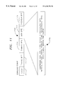
- FIG. 11 is a diagram illustrating the download format which contains a header, training byte, command byte, data bytes, and checksum byte, according to an embodiment of the invention
- FIG. 12 is a schematic showing pointers to protocols and key data stored in a RAM and protocols, key data, pattern fragments, and formats stored in a ROM according to an embodiment of the invention
- FIG. 13 shows a set of pattern fragments according to an embodiment of the invention
- FIG. 14 shows a set of formats according to an embodiment of the invention.
- FIG. 15 shows pointers to protocols and key data stored in a RAM that point to protocols and key data stored in a ROM that also contain pointers to pattern fragments and formats, according to an embodiment of the invention
- FIG. 16 illustrates a timing diagram showing how a pattern fragment and format are used to construct an IR code, according to an embodiment of the invention
- FIG. 17 is a table showing the relationship of a key to output data for that key according to an embodiment of the invention.
- FIG. 18 is a schematic for a universal remote controller having apparatus for downloading a device protocol and key data and a pointer to the device protocol and key data according to an embodiment of the invention
- FIG. 19 illustrates a pointer for a device protocol and key data pointing to a protocol and key data stored in RAM and pointers in the protocol for pointing to a pattern fragment and a format, according to an embodiment of the invention
- FIG. 20 is a schematic for a universal remote controller having apparatus that allows downloading a pattern fragment and a format to a RAM, according to an embodiment of the invention
- FIG. 21 is a diagram showing a pointer to a device protocol and key data in a RAM pointing to a protocol and key data stored in the RAM wherein the protocol contains pointers to a pattern fragment and format stored in the RAM according to an embodiment of the invention
- FIG. 22 is a flow diagram of a method for initializing a universal remote control including storing protocol and key data pattern fragments and formats in the universal remote control and downloading pointers to protocol and key data for devices to be controlled, according to an embodiment of the invention
- FIG. 23 is a flow diagram for a method of generating codes for controlling appliances from a remote controller using pattern fragments stored in the remote controller according to an embodiment of the invention
- FIG. 24 is a method for downloading to a universal remote controller the protocol and key data for controlling an appliance according to an embodiment of the invention.
- FIG. 25 is a flow diagram for a method of downloading to a remote controller a device's protocol, key data, pattern fragment, and format according to an embodiment of the invention
- FIG. 26 is an example of data downloaded to a remote controller for a device to be controlled, according to an embodiment of the invention.
- FIG. 27 is a schematic of a remote controller similar to the remote controller of FIG. 12 with the addition of a decompressor for decompressing entered information according an embodiment of the invention
- FIG. 28 is a schematic of a remote controller similar to the remote controller of FIG. 18 with the addition of a decompressor for decompressing entered data according to an embodiment of the invention
- FIG. 29 is a schematic of a remote controller similar to the remote controller of FIG. 20 with the addition of a decompressor for decompressing entered data according to an embodiment of the invention
- FIGS. 30-32 are flow diagrams for generating codes for controlling appliances from a remote controller including steps of entering data and decompressing the data according to an embodiment of the invention.
- FIG. 1 there is shown a schematic of a conventional universal remote controller, which contains a microprocessor 12 , a random access memory (RAM) 14 , an IR transmitter 16 and a keypad 18 .
- a universal remote controller normally has an interface 20 , through which it is possible to enter IR codes for various appliances into the universal remote controller 10 .
- the universal remote controller 10 learns the IR codes for remote controller 26 via IR codes sent from the remote controller 26 when a user presses a key on keypad 27 .
- the transmitted IR codes are received by IR receiver 22 in the universal remote controller and sent via interface 20 and microprocessor 12 for storage in RAM 14 .
- This is the technique employed in the Ehlers patent referred to above in the Background of the Invention.
- Another technique is to load IR codes into RAM 14 from a computer 24 via the interface 20 .
- FIG. 2 shows the timing of a IR bit stream for an IR code.
- the carrier frequency is transmitted as shown in FIG. 2 elements 34 and 38 .
- the OFF times there is no transmission of the carrier frequency.
- One technique for storing the IR code is to store the time line 31 which reduces the amount of storage as opposed to storing the IR bit stream 33 which includes the carrier frequency. This is the technique employed in the Darbee patent referred to above in the Background of the Invention. In Darbee the carrier is filtered to construct the time line 31 which is then stored in the RAM 14 . Another technique is to store a sequence of ON times and OFF times.
- the length of the ON time 30 would be stored followed by the length of the OFF time 32 followed by the length of the ON time 36 and so on.
- the universal remote controller can be used to send commands corresponding to a key.
- Each key on keypad 27 generates a corresponding IR bit stream 33 .
- a unique ON/OFF time pattern will be stored for each key on the remote controller being mimicked by the universal remote controller.
- FIG. 3 shows a flow diagram of a method for generating the IR bit stream corresponding to a pressed key.
- a key is pressed for the desired function.
- the microprocessor will access the first ON or OFF time from the sequence of ON/OFF times that correspond to the key.
- a timer is set to time the ON time and in step 56 a carrier frequency is generated.
- step 58 when a timer equals the ON time the generation of the carrier frequency is terminated and a timer is set to time the OFF time in step 60.
- steps 62 and 64 NOPs no operations are executed until the time equals the OFF time.
- step 56 it is determined whether the IR code is complete. If the IR code is not complete, then in step 68 the microprocessor accesses the next ON/OFF time from the RAM 14 and steps 54 through 66 are repeated. Finally, the complete IR code will be generated and transmitted and in step 72 the operation is completed.
- a disadvantage with this technique is that an entire sequence of ON/OFF times must be stored for each of the keys.
- the following describes apparatus and methods for generating IR codes for controlling appliances from a remote controller, which avoids the shortcomings of the conventional universal remote controllers.
- An embodiment of an apparatus for using compressed codes for recorder programming is the custom programmer 1100 of FIG. 4 a.
- the purpose of the custom programmer is to significantly reduce the number of keystrokes required to set up the timer preprogramming feature on a VCR. It is only necessary for the user to enter a code with 1 to 8 digits or more into the VCR. This can be done either remotely or locally at the VCR.
- a decoder Built into either the custom programmer is a decoder which automatically converts the code into the proper channel, day, time-of-day, and length (CDTL) programming information and activates the VCR to record a given television program with the corresponding channel, date, time and length.
- CDTL channel, day, time-of-day, and length
- multiple codes can be entered at one time for multiple program selections.
- the code can be printed in a television program guide in advance and selected for use with a VCR or remote controller with the decoding means.
- This instant programmer sold under the VCRPlus+® trademark, consists of a hand-held unit into which compressed codes (each 1 to 8 digits long) for television programs to be recorded are entered. The compressed codes are most commonly found in printed television listings. The instant programmer decodes the compressed codes into channel, date, time-of-day and length commands which are then stored in the programmer's memory.
- the instant programmer When date and time of the program in the memory that is scheduled the nearest to the current time coincides with the current time, as determined by an internal clock, the instant programmer, using an IR transmitter and universal remote technology, sends IR remote control signals to a cable box or a video recorder to change the channel to the correct channel and IR remote control signals to a video recorder to turn the recorder on and begin recording. After the length for the program, stored in memory, has elapsed, an IR remote control signal to stop recording is sent to the video recorder.
- the custom programmer 1100 has number keys 1102 , which are numbered 0-9, a CANCEL key 1104 , a REVIEW key 1106 , a WEEKLY key 1108 , a ONCE key 1110 and a DAILY (M-F) key 1112 , which are used to program the custom programmer 1100 .
- a lid normally covers other keys, which are used to setup the custom programmer 1100 . When lid 1114 is lifted, the following keys are revealed, but not shown in the drawings: SAVE key, ENTER key, CLOCK key, CH key, ADD TIME key, VCR key, CABLE key, and TEST key. Also included in the custom programmer 1100 as shown in FIG.
- FIG. 4 a are the liquid crystal display 1134 and the red warning light emitting diode 1132 , and as shown in FIG. 4 b are IR diodes 1135 and access holes 1136 .
- the two access holes 1136 in the bottom of the custom programmer 1100 are for receiving two contact pins, thereby allowing access to two contact points on the circuit board (not shown) inside the custom programmer 1100 .
- the consumer When using the custom programmer 1100 , the consumer initially performs a set-up sequence, consisting of selecting a protocol for the model/brand of VCR, setting the current real time, selecting a protocol for the model/brand of cable box, and entering a series of channel number assignments.
- This initial set-up sequence for the custom programmer 1100 is somewhat complex and may deter the use of the custom programmer by some consumers.
- custom programmer 1100 includes a microphone opening 1140 through which a microphone inside the custom programmer 1100 can receive electronically coded audio signals that contain the information necessary for the custom programmer's initial set-up and commands to store this information into the custom programmer 1100 .
- a user may call a special phone number which could be a toll-free 800 number, a pay-per-minute 900 number, or a standard telephone number with standard toll charges applying.
- the consumer can speak to an operator who orally inquires from the consumer the information regarding the consumer's VCR model and brand, zip code, model and brand of cable box and the newspaper or other publication which the consumer will use to obtain the compressed codes. This is all the information needed to perform the initial set-up for the custom programmer 1100 . From the zip code information, the operator can determine to which cable system the consumer is connected and can combine this data with the knowledge of which publication the consumer will use to select the correct local channel mapping table for the consumer.
- a designated programming key which is, in the case of the preferred embodiment, the CH key located under lid 1114 .
- the display 1134 with display the message “PHONE1 KEY2. Pressing the “2” numeric key places the custom programmer into the manual set-up mode. Pressing the “ 1 ” numeric key initiates the remote programming mode.
- the custom programmer 1100 is then ready to receive an audio signal and display 1134 displays the message “WAIT”.
- the operator will then direct the consumer to place the earpiece 1142 of the telephone receiver 1144 over the microphone opening 1140 of the custom programmer 1100 as generally shown in FIG. 4 b.
- the earpiece need not be placed directly against the custom programmer 1100 , but may be held more than an inch away from the microphone opening with generally satisfactory results.
- the operator will initiate the downloading of the initial set-up data and initial set-up programming commands transmitted over the telephone line 1146 using audio signals to the consumer's custom programmer 1100 .
- the display 1134 of the custom programmer 1100 will display the message “DONE”. If the reception of the initial set-up data is not successful within a predetermined time limit, red warning light emitting diode 1132 will blink to inform the consumer to adjust the position of the telephone earpiece before another down load of the information is attempted. After a waiting period allowing this adjustment, the initial set-up data and commands are re-transmitted over the telephone line. If after a predetermined number of attempts to download the initial set-up information are unsuccessful, the liquid crystal display 1134 displays the message “FAIL” and the operator is again connected to the consumer allowing the operator to speak to the consumer to provide additional assistance in the positioning of the telephone earpiece.
- a live operator could be provided by the local cable company and the initial set-up information downloaded to the custom programmer 1100 by telephone line, through the existing cable of the cable system, or any other transmission means. If local cable companies supply the live operators, the only information they would need to gather from the consumer would be the VCR brand and model and the publication containing compressed codes that the consumer plans on using, because the local cable company would know the model and brand of cable box installed at the consumer's location and the necessary data regarding the local channel designations for that cable system.
- FIG. 5 is a schematic of the circuitry needed to implement alternative embodiments of the custom programmer 1100 .
- the circuit consists of microcomputer 1150 , oscillator 1152 , liquid crystal display 1154 , keypad 1156 , five way IR transmitters 1158 and red warning light emitting diode 1132 .
- earpiece 1142 generates audio signals which are received by microphone 1162 .
- the audio signals received by microphone 1162 are passed through amplifier 1166 , through a band pass filter 1168 with a cutoff at approximately 1-4 kHz, and through a second amplifier 1170 to a serial port of microcomputer 1150 .
- the functional elements of the custom programmer 1100 are embedded within a telephone set 1550 .
- the telephone set can perform all of the compressed code decoding and VCR programming functions of the custom programmer.
- the telephone set can operate as an universal remote controller for controlling appliances such as televisions, cable boxes, VCRs and satellite receivers.
- the telephone set 1550 is connected directly to the telephone network, as shown by telephone connection 1582 .
- the telephone connection is to a telephone network, and the connection can be via telephone lines or via a cellular network.
- the telephone set comprises a telephone base unit 1554 into which a cordless telephone 1552 is inserted.
- the telephone base unit can hold the cordless telephone and also charge the batteries of the cordless telephone.
- a telephone set that does not include a cordless telephone is another embodiment that is not shown, but such a telephone set operates very similarly to the description that follows for the telephone base unit except there would not be a cordless telephone or an RF link to the cordless telephone.
- the cordless telephone 1552 includes controls 1562 and controls 1564 which provide the controls of custom programmer 1100 and also the controls required for a universal remote controller, such as channel and volume up and down keys and VCR, CD, TV, CABLE and AUX select buttons.
- the cordless telephone also includes a display 1566 corresponding to display 1134 of custom programmer 1100 .
- An antenna 1570 is included on the cordless telephone to provide a RF link to the telephone base unit.
- An IR transparent cover 1568 covers an IR transmitter and in one embodiment also an IR receiver.
- the telephone base unit 1554 includes controls 1578 and 1576 which correspond to the controls 1562 and 1564 on the cordless telephone.
- the telephone base unit also includes antenna 1574 for providing an RF link to the cordless telephone 1552 .
- the telephone base unit can also contain a display 1572 corresponding to display 1566 on the cordless telephone.
- the telephone base unit can have a direct wall power connection 1580 and be connected directly to the telephone line via connection 1582 . Alternatively, the connection to the telephone network can be via a cellular network.
- FIG. 6 shows one possible design in which the telephone base unit 1554 has a semicircular tower 1584 that is designed to hold the cordless telephone 1552 .
- the tower 1584 also has the function of providing an elevated tower for holding IR transmitters and an IR receiver.
- IR transmitters can be located around the top of the tower pointing in an upward direction, a right direction, a left direction, a rear direction and a forward direction. The multiple IR transmitters insure that the telephone base unit will communicate properly with the appliances to be controlled regardless of the orientation of the telephone unit with respect to those units. IR receivers can be placed at the top of the tower 1584 for receiving information from the appliances.
- appliances and the term devices include televisions, cable boxes, satellite receivers, VCRs, stereos and other similar equipment, including any remote controller for the various apparatus.
- the terms also include other apparatus such as heaters, thermostats, washing machines, ovens, lights, and computers.
- FIG. 7 shows the telephone base unit 1554 located on a table near a video cassette recorder 1602 , a cable box 1604 and a television 1600 .
- the cordless telephone 1552 which can be in the same room as the telephone base unit or be in a different room, communicates with the telephone base unit via RF signals 1606 .
- the telephone base unit controls the VCR, cable box, and television set via IR signals 1601 .
- the cordless telephone if it is in the same room as the appliances, can also control the appliances via transmission signals 1603 , which can be IR signals, or RF signals if the appliances contain an RF receiver.
- Television signals can contain embedded information which can be extracted by the VCR and transmitted to the telephone base unit or to the cordless telephone via transmission signals 1605 , which can be IR signals, or RF signals if the appliances contain an RF transmitter.
- FIG. 8 is a block diagram of the cordless telephone.
- the cordless telephone has a microcomputer 1610 , which consists of a CPU, ROM, RAM, I/O ports, timers and counters, and a clock.
- the microcomputer is used to implement the decoding of compressed codes having at least one digit into channel, time-of-day and length commands. Programs stored in the memory of the microcomputer also are instrumental in implementing the other functions of the cordless telephone including the functions of an universal remote controller.
- the microcomputer has an input from an oscillator 1612 and inputs from the keypad 1616 on the cordless telephone.
- the microcomputer drives a LCD display 1614 and also drives a warning light-emitting diode 1624 .
- the cordless telephone can send commands to appliances through the IR transmitter 1620 or the RF transmitter 1618 and can receive information from the appliances via IR receiver 1622 or the RF receiver 1618 .
- a battery provides power to the cordless telephone and can be charged from the telephone base unit.
- FIG. 9 shows a block diagram of the telephone base unit 1554 .
- the telephone base unit has a microcomputer 1630 which contains a CPU, ROM, RAM, I/O ports, timers and counters, and a clock.
- the microcomputer is used to implement the decoding of compressed codes having at least one digit into channel, time-of-day and length commands. Programs stored in the memory of the microcomputer also are instrumental in implementing the other functions of the telephone base unit.
- the microcomputer has input from an oscillator 1632 and from a keypad 1636 on the face of the telephone base unit.
- the microcomputer drives a LCD display 1634 on the telephone base unit and also drives a warning light-emitting diode 1644 .
- the telephone base unit can send commands to the appliances via five-way IR transmitter 1640 , which can transmit to the front, the back, left, right and up to insure communication with the appliances, or via RF transmitter 1638 .
- Information from the appliances can be received by the telephone base unit via IR receiver 1642 or via RF receiver 1638 .
- the telephone base unit contains a converter 1643 for providing power from wall power to the telephone base unit and for charging the cordless telephone battery.
- the telephone base unit has a direct connection with telephone line 1646 via telephone circuit 1648 which communicates to a DTMF decoder 1650 for input to the microcomputer 1630 .
- the telephone base unit could be connected to the telephone network via a cellular network.
- the microcomputer 1630 can communicate to the telephone circuit 1648 either directly or via voice generator 1652 .
- the voice generator can synthesize speech for requesting a user to enter certain numbers, such as a password or a telephone number.
- the telephone base unit and cordless telephone perform all of the functions of the custom programmer 1100 and the functions of a universal remote controller.
- Compressed code decoding for codes compressed from channel, day, time-of-day, and length is performed by the microcomputers in either the telephone base unit or the cordless telephone and, at the appropriate time, record-on commands are sent to the VCR 1602 , and channel-select commands are sent to the cable box 1604 , a satellite receiver, and/or the TV 1600 . Then, when recording is complete according to the decoded length from the CDTL information for a program to be recorded, the VCR 1602 is commanded to stop recording.
- the warning light-emitting diode 1624 in the cordless telephone and the warning light-emitting diode 1644 in the telephone base unit have the same function, which is to warn the user that a program is about to be recorded so that a tape is loaded into the VCR, as the warning light 1132 of custom programmer 1100 .
- Commands can also be sent to a television set based on decoded CDTL information, to turn on a television and switch to the correct channel at the appropriate time for a program, and then turn off the television when the program is over. This is especially useful for handicapped people.
- FIG. 10 is a flow diagram of a method for downloading initial setup data to the telephone base unit via the telephone network.
- the method is also applicable for the custom programmer 1100 , and makes the initial set-up much easier.
- the user calls a representative at a remote site.
- the user identifies his zip code, the cable carrier, the television guide used by the user, and the model and brand of the VCR, cable box and any other appliances to be controlled, such as a satellite receiver.
- the representative enters this data into a computer, and then in step 1696, the computer downloads initial setup data via telephone to the telephone base unit or custom programmer.
- the telephone base unit via the RF antenna sends initial setup data to the cordless telephone.
- the download method can be used with an universal remote controller.
- FIG. 11 shows the download format 1700 for downloading information to the custom programmer 1100 or the telephone set 1550 via telephone.
- Each binary bit that is sent for the download via telephone is represented by three sine wave cycles of the same frequency.
- Bit 1 is three cycles of 1.8 kHz and bit 0 is three cycles of 2.8 kHz.
- the receiver such as the custom programmer, locks onto the middle cycle and detects whether it is binary 0 or 1.
- the header 1710 consists of 10 leading binary zeros and ones and is followed by a training byte 1712 , a command byte 1714 , a series of data bytes 1716 , and the last byte, which is check sum byte 1718 .
- the total number of the data bytes depend on the command byte 1714 , but the maximum number should not be greater than 13. Every byte will be nine bits long with one bit of odd parity.
- the training byte 1712 is defined as binary 1010 0101, or Hex A5 with the parity binary 1.
- the command byte is used to explain the data that follows the command byte.
- the command byte for a compressed code may be 1000 0000 (80H) and the command byte for the clock data may be 1001 0000 (90H).
- the command types include: compressed code, CDTL, clock, pointer for a device, protocol, key data, pattern fragment, format, header/ending timing, reset, channel mapping and RAM dumping.
- the data is a compressed code, then the data is 6 bytes long.
- the unused nibble/bytes will be filled with FXH or FFH.
- the last byte is the record frequency—C1H is ONCE, C2H is WEEKLY and C3H is for DAILY.
- the data is 7 bytes long.
- the first byte is the guide channel number.
- the second byte is the day.
- the third byte is the start hour and then the start minute in 24 hour format.
- the fifth byte is the hours of program length and followed by the minutes of program length.
- the last byte is the ONCE, WEEKLY or DAILY. All data are in Hex form.
- the ONCE is represented by C1H, WEEKLY by C2H and DAILY by C3H.
- Clock data is 6 bytes long. The first byte is YEAR and then, MONTH, DAY, HOUR, MINUTE and SECOND. All data are in Hex form. The hour is a 24 hour clock.
- the data is a Pointer for a Device
- the data is 3 bytes long.
- the first byte is the device name. 01 for VCR, 02 for CABLE, 03 for TV and 04 for AUX.
- the second and third bytes are pointers to the protocol and key data for the device. This setting is used for a KNOWN device that is a device with entries stored in ROM in the remote controller.
- E1H for VCR code E2H for cable code
- E3H for TV code E4H for AUX code.
- the third byte XXH is the type of E1H if it is an existing type.
- the third byte will be CXH if it is a New type.
- Protocol data and in particular the pattern fragment type is 12 bytes long.
- the protocol data includes a pattern fragment pointer.
- the set of pattern fragments which can be accessed by the pattern fragment pointer include:
- a format pointer Also included in the protocol data is a format pointer.
- a set of format types, which can be accessed by the format point include:
- the 4th to 7th bytes store the timing information of binary 0 while the 8th to 11th bytes store the timing information of binary 1.
- the 4th and 5th bytes are interbit pattern timing for binary 0 from 1 us to 65 ms and the 6th and 7th bytes are the timing of binary 0 from 1 us to 65 ms with a resolution of 1 us.
- the last (12th) byte is the Carrier frequency (CF) from 0.5 to 120 us in steps of 0.5 us. If the CF byte is 00H, it means 400 kHz carrier frequency.
- CF Carrier frequency
- the key data is the data for each key and is 10 bytes long.
- the first byte is the mode byte from E 1 H to E 4 H, which identifies the device.
- the second byte is the key name number. Every 10 bytes stores key data for two keys. For example,
- ABH stores the key data for “Power” and “Record”.
- the sets of pattern fragments and formats can be sent in the data bytes.
- the timing for the Header and Ending is 10 bytes.
- the first byte is the type number C1H to C4H followed by the CEH if it is a Header or CFH if it is an Ending.
- the 3rd to 10 bytes store the timing information.
- a reset data code is one byte long. It contains a special reset code to set the remote controller in an initial condition.
- Data for channel mapping which is a mapping between local channels and cable channels is 11 bytes long.
- the first byte stores the total number of mapped channels.
- the second and third bytes are a pair of local and cable channels.
- the fourth and fifth bytes for the next pair and so on.
- Data for RAM dumping is used for directly dumping the RAM memory via the telephone.
- the first byte is the ADDRESS of the first data location and then the total number of bytes to be dumped follows. A total of 10 RAM locations can be downloaded for each download format 1700 . This feature allows a remote site to access to the RAM contents.
- the checksum byte is the exclusive OR (XOR) of all the data bytes and is also 9 bits long. Data will not be accepted if the check sum is incorrect.
- FIG. 12 is a schematic of a portion of custom programmer 1100 , the telephone set 1550 or an universal remote controller according to this invention.
- the portion shown in FIG. 12 includes a microcomputer 1800 , IR transmitter 1802 , a keypad 1804 and an interface 1806 through which downloaded information can be passed to RAM 1830 .
- the interface 1806 can be coupled directly to a telephone line 1820 , as is the case for telephone set 1550 or via the telephone 1822 and the telephone earpiece 1824 through microphone 1808 , which corresponds to microphone 1162 of custom programmer 1100 .
- Another path for downloading information to the interface is via audio player 1826 and speaker 1828 and microphone 1808 . For example, a user may obtain a tape which can be played on the audio player.
- the tape has recorded audio which is in the same format as the downloaded information via the telephone 1822 .
- the downloaded information is received by the interface then the information is stored in RAM 1830 via databus 1801 and address bus 1803 .
- the databus 1801 and the address bus 1803 are coupled to the microcomputer 1800 , ROM 1850 , and RAM 1830 .
- device protocols and key data are stored in ROM 1850 .
- ROM 1850 Also stored in ROM 1850 are a set of pattern fragments and a set of formats. Illustrated in FIG. 12 are device 1 protocol 1852 , device 2 protocol 1854 and device N protocol 1855 . Also illustrated in FIG. 12 are device 1 key data 1870 , device 2 key data 1872 and device N key data 1873 .
- the pattern fragments are shown as the set E 1 to EN ( 1880 ) and the formats are shown as the set A 1 to AM ( 1890 ).
- Each protocol consists of a pattern fragment pointer, a format pointer, a zero timing, a one timing and a carrier frequency.
- the key data consists of data that is transmitted to an appliance or device when a key on the remote controller is pressed.
- the ROM 1850 can also store X wait pattern 1893 , Y wait pattern 1894 , Header 1895 and Ending 1896 .
- pointers to the protocol and key data can be downloaded.
- the pointers to the protocol and key data are stored in RAM 1830 as indicated by VCR pointer 1832 and cable pointer 1834 .
- the pointer 1832 is a mapping between a device model number and a pointer to the protocol/key data. This allows the microcomputer 1800 to access the protocol and key data for a particular device such as a VCR.
- the protocol and key data are used to generate codes that are transmitted to control an appliance or device.
- the device protocol contain a pattern fragment pointer and a format pointer, such as pattern pointer 1856 and format pointer 1858 shown in FIG. 12 . These pointers point to a particular pattern fragment in the set of pattern fragments 1880 and a particular format in the set of formats 1890 .
- FIG. 13 is a table showing the pattern fragment names, and the pattern fragments for a 0 bit and a 1 bit.
- the first pattern fragment type is called the Interbit pattern (EO) and has a pattern fragment name E 0 (element 2000 ). Appliances that use this type of pattern fragment are sensitive to delay time for distinguishing a 0 and a 1 bit. As shown, the 0 bit ( 2010 ) has a shorter delay time than the 1 bit (element 2012 ). The appliances look for a trigger which is just a short period of infrared carrier frequency, and then the appliance waits to see how long the delay is until the next trigger.
- EO Interbit pattern
- E 0 pattern fragment name
- Appliances that use this type of pattern fragment are sensitive to delay time for distinguishing a 0 and a 1 bit. As shown, the 0 bit ( 2010 ) has a shorter delay time than the 1 bit (element 2012 ).
- the appliances look for a trigger which is just a short period of infrared carrier frequency, and then the
- the next pattern fragment type is called the Pulse type (E 1 ) and it is similar to the Interbit pattern, but the trigger is short compared to the Interbit pattern.
- the next pattern fragment (E 2 ) is called the Reverse Interbit pattern and it is similar to the Interbit pattern except the infrared carrier time is what differentiates a 0 from a 1 bit. The wait time does not change.
- the next pattern type (E 3 ) is called the High-Low pattern fragment type. A 0 bit has silence and then infrared carrier. A 1 bit has infrared carrier then silence.
- the next pattern fragment type is the Serial pattern fragment type (E 4 ). In this pattern a 0 bit and a 1 bit take exactly the same amount of time to transmit.
- a 0 bit is a set amount of time of infrared carrier and a 1 bit is a set amount of time of silence, or no infrared carrier.
- Another pattern (E 5 ) is called the Missing Pulse pattern fragment type and for this pattern fragment the difference between a 0 bit and a 1 bit is the “count” of pulses in a fixed amount of time. Each pulse has approximately the same number of carrier frequency cycles contained within the pulse.
- FIG. 14 is a table of the set of formats for transmitting codes to control an appliance. Any particular appliance uses one of the formats in the set of formats.
- the A 1 format (element 2030 ) has a format DX. The corresponding description for DX is data, wait. The data that is inserted into the data portion of the format is retrieved from the key data for the device.
- Another format is format A 2 (element 2034 ) that has an address, data, wait format which can be abbreviated as ADX.
- the address is just another series of databits.
- a Sony VCR may have an address of 0100, and a second Sony VCR may have an address of 1001.
- the same data value of 150 may represent “power” but each of the Sony VCRs will only respond to the correct address. So if the data value for 150 is 10010110, to send power to Sony VCR no. 1 the databits 010010010110 must be sent. To send power to Sony VCR no. 2 the databits would be 011110010110.
- the X and Y wait values in a format are additional infrared carrier and delay times that usually appear at the end of the databit.
- format A 4 the format is HADX, which is header, address, data and wait.
- the header is essentially a code that is sent to the appliance to wake up the appliance so that it can receive the following address and databits.
- format AF is a format of header, address, data, inverse address, inverse data, wait ending, and wait. In this format the address and data are sent in both a positive and an inverse mode so that the appliance that receives the address and data can check whether the address and data are properly received.
- the X wait, Y wait, header, and ending can be stored in ROM 1850 , as shown in FIG. 12 elements 1893 , 1894 , 1895 and 1896 .
- FIG. 15 illustrates some example key data.
- Key data corresponds to each key that will be used to send commands to an appliance.
- the key data is 001011 (element 2122 ).
- the key data is inserted into the D field of the format.
- FIG. 16 illustrates how the pointers to the device protocol and key data are used to access the data from the ROM 1850 in order to generate a code to control an appliance.
- the remote controller which can be, for example, custom programmer 1100 or telephone set 1550 , including the cordless telephone 1552
- the microcomputer 1800 uses the corresponding pointers to the protocol and key data to access the protocol and key data for a particular device. For example, if device 1 as shown in FIG. 16 is being controlled then the pointer 1832 will be accessed from RAM 1830 and used to access device 1 protocol 1852 and device 1 key data 1870 from the ROM 1850 .
- the pointer 1834 will be accessed from RAM 1830 in order to access device N protocol 1855 and device N key data 1873 from the ROM 1850 .
- the pattern fragment pointers and the format pointers such as pattern pointer 1852 and format pointer 1858 are used to access a pattern fragment and a format such as pattern fragment 1882 and format 1892 , as shown in FIG. 16 .
- device 1 protocol uses pattern fragment type E 0 and format type A 3 . Note that device N and device 1 both use format type A 3 .
- FIG. 17 illustrates how device protocol and key data are combined to generate an infrared code for transmittal to the appliance being controlled.
- pattern fragment E 5 which is a Missing Pulse pattern fragment type is to be used.
- the protocol also indicates a one timing and a zero timing.
- a 1 is generated as a combination of the pattern fragment for a 1 (element 2100 ) and the timing for a 1 (element 2104 ).
- a 0 is formed by the pattern fragment for a 0 (element 2102 ) and the timing for a 0 (element 2106 ).
- format type A 7 which consists of a header followed by the data, which is in this case key data 2108 .
- a message 2109 By combining the pattern fragment, the timing for 0, the timing for 1, and the format type, a message 2109 can be generated. Then, the carrier frequency 2110 as indicated in the protocol is mixed with the message 2109 to generate infrared code 2112 which is then transmitted to the appliance.
- the downloaded data from the telephone line 1820 , the telephone earpiece 1824 or the speaker 1828 includes protocol and key data for an appliance that does not have device protocol and key data stored in ROM 1850 .
- the protocol for the new device and the key data for the new device into RAM 2140 , as shown in FIG. 18 .
- a pointer 2160 to the protocol and key data for device X has been downloaded and stored in RAM 2140 .
- downloaded protocol 2142 which consists of a pattern fragment pointer 2146 , a format pointer 2148 , a 0 timing 2150 , a 1 timing 2152 and a carrier frequency 2154 .
- Key data 2144 has also been downloaded and stored in RAM 2140 .
- FIG. 19 illustrates how the data that is downloaded to RAM 2140 is used for generating infrared codes for controlling an appliance.
- the downloaded pointer 2160 is used to access the protocol for the device 2142 and the key data for the device 2144 , which are both stored in RAM 2140 .
- the pattern fragment type is a type that has been previously stored in ROM 1850 .
- the pattern fragment pointer 2146 is used to access a pattern fragment from the pattern fragment set stored in the ROM 1850 .
- the pattern fragment accessed is type E 4 (element 2160 ).
- the format pointer 2148 is used to access format A 2 (element 2162 ) from ROM 1850 .
- the pattern fragment, the timing for 0, the timing for 1, the format, and the carrier frequency of the protocol 2142 are then used to generate an IR code in the manner illustrated in the FIG. 17 .
- FIG. 20 is similar to FIG. 18 and illustrates data that is downloaded to RAM 2140 when the device to be controlled is a device that does not have protocol, key data, a pattern fragment, and a format stored in ROM 1850 corresponding to the device.
- the protocol 2168 and the key data 2169 as shown in FIG. 20 are downloaded for the new device X in the same manner as protocol 2142 and key data 2144 shown in FIG. 18 .
- Pointer 2190 which points to the protocol and key data is also downloaded and stored in the RAM 2140 .
- pattern fragment 2180 and format 2182 are downloaded via interface 1806 and stored in RAM 2140 .
- FIG. 21 shows how the information that is downloaded and stored in RAM 2140 is used to generate infrared codes to control an appliance.
- the pointer 2190 is used to access the protocol 2168 and the key data 2169 for the device.
- the pattern fragment pointer 2170 is used to access pattern fragment 2180 and the format pointer 2172 is used to access the format 2182 .
- the pattern fragment 2180 , the format 2182 , the timing for a 0 2174 , the 1 timing 2176 , and the carrier frequency 2178 are used in the manner illustrated in FIG. 17 to generate an IR code.
- FIG. 22 is a flow diagram for storing or downloading and storing the information required to generate IR codes.
- protocols for selected device model numbers are stored in read only memory, such as read only memory 1850 .
- key data for selected device model numbers are stored in read only memory. Each key data consists of data for each key for each device model number. Each protocol consists of a pattern fragment pointer, a format pointer, a 0 timing, a 1 timing and a carrier frequency.
- a set of pattern fragments for generating codes are stored in read only memory.
- a set of formats are stored in read only memory.
- pointers to protocol and key data for each device are downloaded from a remote site and stored in a memory.
- FIG. 23 describes a method of using stored information for generating codes for a device to be controlled by a remote controller.
- the device to be controlled is to be identified.
- a key for the desired command or function is pressed on the remote controller.
- a protocol consisting of a pattern fragment pointer, a format pointer, a 0 timing, a 1 timing and a carrier frequency are accessed from memory for the identified device by using a pointer to a protocol for the device.
- key data corresponding to the pressed key is accessed from memory by using a pointer to key data for the device.
- a pattern fragment is accessed by using the pattern fragment pointer in the protocol.
- step 2310 a 0 form and a 1 form are generated by using the pattern fragment and timing for a 0 and a 1.
- step 2312 the format is accessed by using the format pointer in the protocol.
- step 2314 a message is generated by using the format, the 0 form, the 1 form, and the key data.
- the message is then mixed with a carrier frequency in step 2316 to form an infrared code that is transmitted to the appliance or device to be controlled.
- FIG. 24 The method described in FIG. 24 is illustrated in FIG. 17 and can be used for generating codes by the remote controllers of FIG. 12, FIG. 18, and FIG. 20, which operate with varying downloaded data.
- the downloaded data is the data shown in step 2208 of FIG. 22 .
- the downloaded data and a method for downloading the data are illustrated in FIGS. 24 and 25, respectively.
- a protocol is downloaded from a remote site and stored in memory.
- the protocol for a device consists of a pattern fragment pointer, a format pointer, a zero timing, a 1 timing and a carrier frequency.
- key data for the device consisting of data for each key is downloaded from a remote site and stored in memory.
- pointers to the protocol and the key data are downloaded from a remote site and stored in memory.
- the set of pattern fragments and the set of formats are stored in a read only memory in the same manner as steps 2204 and 2206 of FIG. 22 .
- FIG. 25 illustrates a method for downloading information from a remote site to the remote controller of FIG. 20 .
- a protocol for a device is downloaded from a remote site and stored in memory.
- the protocol consists of a pattern fragment pointer, format pointer, 0 timing, 1 timing, and a carrier frequency.
- key data for the device consisting of data for each key is downloaded from the remote site and stored in memory.
- a pattern fragment that can be used to generate 0's and 1's for the device is downloaded from the remote site and stored in memory.
- a format that can be used to generate codes for the device is downloaded from the remote site and stored in memory.
- pointers to the protocol and the key data for the device are downloaded from a remote site and stored in memory.
- FIG. 26 shows a representative set of download data that would be downloaded for device A.
- FIG. 27 is a schematic of a remote controller and is very similar to FIG. 12 .
- FIG. 27 differs from FIG. 12 in that there is an additional element which is decompressor 1805 that has an input from microcomputer 1800 and an output to microcomputer 1800 .
- the remaining portions of FIG. 27 are identical to FIG. 12 and operate in the same manner as the remote controller of FIG. 12 .
- the purpose of the decompressor is to decompress data that is entered in compressed form to the remote controller.
- the remote controller of FIG. 27 can be incorporated into custom programmer 1100 or telephone set 1550 , including cordless telephone 1552 .
- Compressed data can be entered into the remote controller via keypad 1804 , via telephone line 1820 , or via telephone earpiece 1824 or speaker 1828 . Once the entered data has been decompressed and stored in RAM then the data is used in the same manner as the data is used in FIG. 12 . For example, pointers to the protocol and key data for a device can be entered as compressed data and decompressed by decompressor 1805 .
- decompressing can be performed by special hardware such as shown in FIG. 27 or the decompression can be performed by microcomputer 1800 .
- FIG. 28 shows a schematic of a remote controller that is similar to the remote controller shown in FIG. 18 .
- decompressor 1805 has been added and is coupled to the microcomputer 1800 .
- the decompressor 1805 is used to decompress data that has been entered in compressed form.
- the entered data which can be decompressed by decompressor 1805 can include protocol data, key data, and pointers to the protocol and key data for a device.
- the protocol includes a pattern fragment pointer, a format pointer, a zero timing, a one timing, and a carrier frequency.
- the compressed data that is entered can be entered via keypad 1804 , microphone 1808 or a direct connection with telephone line 1802 .
- the microcomputer 1800 can perform the decompression function.
- FIG. 29 shows a remote controller that is similar to remote controller shown in FIG. 20 .
- the remote controller of FIG. 29 includes a decompressor 1805 which has the purpose of decompressing data that is entered into the remote controller in compressed form.
- the compressed data can be entered via keypad 1804 , microphone 1808 or via direct telephone connection 1820 .
- the decompression function can be performed by decompressor 1805 or by microcomputer 1800 .
- the remote controller shown in FIG. 29 operates identical to the remote controller of FIG. 20 .
- FIG. 30 is a flow diagram of a method for generating codes for controlling appliances.
- protocols for a selected device are stored in read only memory. Each protocol consists of a pattern fragment pointer, a format pointer, a zero timing, a one timing and a carrier frequency.
- key data for the selected device is stored in read only memory.
- a set of pattern fragments are stored in read only memory and in step 2626 a set of formats is stored in read-only memory.
- pointers to the protocol and key data for a device are entered via a keypad. Then the entered pointers are decompressed and stored in memory. The entry can also be via other forms such as a telephone line or a microphone on the remote controller.
- codes can be generated using the method described in FIGS. 17 and 23.
- the method of FIG. 30 can be used to store and enter data into the remote controller of FIG. 27 .
- FIG. 31 is a flow diagram of a method for entering data into a remote controller for generating codes for controlling appliances.
- a protocol for a device is entered via a keypad.
- the protocol consists of a pattern fragment pointer, a format pointer, a zero timing, a one timing, and a carrier frequency.
- the entered protocol is decompressed and then stored in memory.
- key data for the device consisting of data for each key on the device that will be used to control the appliance is entered via the keypad. Then the entered key data is decompressed and stored in memory.
- pointers to the protocol and the key data for the device are entered via key pad, decompressed and then stored in memory.
- the data entered in FIG. 31 via the keypad can also be entered via a telephone line or a microphone on the remote controller.
- the remote controller shown in FIG. 28 can be used to generate codes for controlling an appliance in accordance with the method described in FIGS. 17 and 23.
- FIG. 32 shows another method for generating codes for controlling an appliance.
- a protocol for a device consisting of a pattern fragment pointer, a format pointer, a zero timing, a one timing, and a carrier frequency is entered via keypad and decompressed and stored in memory.
- key data for the device consisting of data for each key is entered via keypad, decompressed and stored in memory.
- a pattern fragment for the device is entered via keypad, decompressed and stored in memory.
- the format for the device is entered via keypad, decompressed and stored in memory.
- pointers to the protocol and the key data for the device are entered via keypad, decompressed and stored in memory.
- the entry of the data for steps 2640-2648 can be via a telephone line or via a microphone on the remote controller rather than the keypad.
- compression and decompression techniques There are many possible compression and decompression techniques.
- One form of compression would be to use Huffman coding.
- the effect of any compression technique is to reduce the number of key strokes for entering the data or to reduce the amount of data that needs to be transmitted, for example, over a telephone line.
Abstract
Description
Claims (15)
Priority Applications (1)
| Application Number | Priority Date | Filing Date | Title |
|---|---|---|---|
| US09/036,852 US6204796B1 (en) | 1994-07-01 | 1998-03-09 | Apparatus and methods for generating codes for controlling appliances from a remote controller |
Applications Claiming Priority (3)
| Application Number | Priority Date | Filing Date | Title |
|---|---|---|---|
| US26984794A | 1994-07-01 | 1994-07-01 | |
| US76301096A | 1996-12-10 | 1996-12-10 | |
| US09/036,852 US6204796B1 (en) | 1994-07-01 | 1998-03-09 | Apparatus and methods for generating codes for controlling appliances from a remote controller |
Related Parent Applications (1)
| Application Number | Title | Priority Date | Filing Date |
|---|---|---|---|
| US76301096A Continuation | 1994-07-01 | 1996-12-10 |
Publications (1)
| Publication Number | Publication Date |
|---|---|
| US6204796B1 true US6204796B1 (en) | 2001-03-20 |
Family
ID=26953936
Family Applications (1)
| Application Number | Title | Priority Date | Filing Date |
|---|---|---|---|
| US09/036,852 Expired - Fee Related US6204796B1 (en) | 1994-07-01 | 1998-03-09 | Apparatus and methods for generating codes for controlling appliances from a remote controller |
Country Status (1)
| Country | Link |
|---|---|
| US (1) | US6204796B1 (en) |
Cited By (45)
| Publication number | Priority date | Publication date | Assignee | Title |
|---|---|---|---|---|
| US20020021309A1 (en) * | 2000-06-30 | 2002-02-21 | Tara Burnhouse | Future program action indication display |
| WO2002030129A1 (en) * | 2000-09-29 | 2002-04-11 | Digeo, Inc. | Methods for audio capture and communication during television broadcasts |
| US20020054206A1 (en) * | 2000-11-06 | 2002-05-09 | Allen Paul G. | Systems and devices for audio and video capture and communication during television broadcasts |
| US20020080044A1 (en) * | 2000-12-27 | 2002-06-27 | Samsung Electronics Co., Ltd. | Method for generating and transmitting/receiving input codes in universal input device and apparatus thereof |
| US20020100063A1 (en) * | 2000-09-08 | 2002-07-25 | Dale Herigstad | Video interaction |
| US20020167617A1 (en) * | 2001-05-11 | 2002-11-14 | Vornsand Steven J. | Closed loop television control system |
| US6529233B1 (en) * | 2000-09-29 | 2003-03-04 | Digeo, Inc. | Systems and methods for remote video and audio capture and communication |
| US20030066080A1 (en) * | 2001-10-02 | 2003-04-03 | John Kamieniecki | Method and apparatus for automatic set-up of electronic devices |
| US20030117294A1 (en) * | 2001-12-05 | 2003-06-26 | Yoichi Hatano | Remote control transmitter and transmit/receive system using the same |
| US20030146928A1 (en) * | 2002-01-31 | 2003-08-07 | Paul Finster | Method and system for optimal grid alignment |
| US6606280B1 (en) * | 1999-02-22 | 2003-08-12 | Hewlett-Packard Development Company | Voice-operated remote control |
| US20030167471A1 (en) * | 2002-03-04 | 2003-09-04 | Cliff Roth | System and method for selection of video products that are deliverable on demand |
| US20040120716A1 (en) * | 2002-12-05 | 2004-06-24 | Contec Corporation | Programmable universal remote control unit and method of programming same |
| US6791467B1 (en) * | 2000-03-23 | 2004-09-14 | Flextronics Semiconductor, Inc. | Adaptive remote controller |
| US20040198251A1 (en) * | 2003-02-13 | 2004-10-07 | The Chamberlain Group, Inc. | Method and apparatus for remote control |
| US20040244056A1 (en) * | 2001-02-21 | 2004-12-02 | Lorenz Kim E. | System and method for providing direct, context-sensitive customer support in an interactive television system |
| US20050039214A1 (en) * | 2001-02-21 | 2005-02-17 | Lorenz Kim E. | System and method for providing direct, context-sensitive customer support in an interactive television system |
| US6882286B1 (en) * | 1999-04-20 | 2005-04-19 | Funai Electric Co., Ltd. | Remote controller and electrical apparatus controlled by the same |
| US20050116851A1 (en) * | 2003-10-24 | 2005-06-02 | Infineon Technologies Ag | Method for digital/ analog conversion and corresponding digital/ analog converter device |
| WO2006042290A2 (en) * | 2004-10-12 | 2006-04-20 | Scope Seven Inc. | Multiple transmitter remote control system |
| US20060161812A1 (en) * | 2005-01-20 | 2006-07-20 | Lg Electronics Inc. | Remote controller code format(s), transmitting/receiving apparatus thereof, and transmitting/receiving method(s) thereof |
| US20060262002A1 (en) * | 2003-03-28 | 2006-11-23 | Universal Electronics Inc. | System and method for using an universal remote control to access extended operational functions of a device |
| US7155213B1 (en) | 2005-09-16 | 2006-12-26 | James R. Almeda | Remote control system |
| US20070046494A1 (en) * | 2004-02-27 | 2007-03-01 | Xiangdong Chen | System and method for providing operation of internet powered universal remote controller |
| US20070046493A1 (en) * | 2005-08-26 | 2007-03-01 | Samsung Electronics Co., Ltd. | Home appliance control apparatus and method |
| US20070052549A1 (en) * | 2005-08-22 | 2007-03-08 | Contec Corporation | Apparatus and method for updating encoded signal information stored in a remote control unit through direct key entry |
| US7224903B2 (en) | 2001-12-28 | 2007-05-29 | Koninklijke Philips Electronics N. V. | Universal remote control unit with automatic appliance identification and programming |
| US20070222634A1 (en) * | 2002-12-10 | 2007-09-27 | Kramer Kenneth J | Advertising apparatus |
| US20070223870A1 (en) * | 2006-03-23 | 2007-09-27 | Seagate Technology Llc | Single board digital video system |
| US20070225828A1 (en) * | 2006-03-24 | 2007-09-27 | Universal Electronics Inc. | System and method for defining a controlled device command set |
| US20070247323A1 (en) * | 2006-03-22 | 2007-10-25 | Funai Electric Co., Ltd. | Remote controller |
| US20070276794A1 (en) * | 2006-02-24 | 2007-11-29 | Hiroyasu Nishiyama | Pointer compression/expansion method, a program to execute the method and a computer system using the program |
| US20080039019A1 (en) * | 2001-02-01 | 2008-02-14 | Ack Venture Holdings, A Connecticut Corporation | Mobile computing and communication |
| US20080040272A1 (en) * | 2000-01-07 | 2008-02-14 | Ack Venture Holdings, Llc, A Connecticut Corporation | Mobile computing and communication |
| US20080297369A1 (en) * | 2004-10-12 | 2008-12-04 | Scope Seven Inc. | Remote Control System with Satellite Control Devices |
| US7487101B1 (en) * | 1997-11-12 | 2009-02-03 | I-Flow Corporation | Method and apparatus for monitoring a patient |
| US20090090704A1 (en) * | 2007-10-09 | 2009-04-09 | Halpin Mark E | Pager system for cooking device |
| US20090167491A1 (en) * | 2003-08-18 | 2009-07-02 | Bloomberg Finance L.P. | Portable access device |
| US20110146776A1 (en) * | 2009-12-18 | 2011-06-23 | E.I. Du Pont De Nemours And Company | Glass compositions used in conductors for photovoltaic cells |
| US20120310867A1 (en) * | 2010-11-26 | 2012-12-06 | Cybio Electronic (Shenzhen) Company Limited | Method for Learning Remote Control and Learning Remote Control Thereof |
| US20150244471A1 (en) * | 2014-02-26 | 2015-08-27 | Contec, Llc | Control Device Update |
| US9305590B2 (en) | 2007-10-16 | 2016-04-05 | Seagate Technology Llc | Prevent data storage device circuitry swap |
| CN105869383A (en) * | 2016-04-13 | 2016-08-17 | 北京精益理想科技有限公司 | Infrared data processing method, infrared instruction calling method and infrared instruction calling system |
| US9679602B2 (en) | 2006-06-14 | 2017-06-13 | Seagate Technology Llc | Disc drive circuitry swap |
| CN110618961A (en) * | 2019-08-22 | 2019-12-27 | 苏州浪潮智能科技有限公司 | Method and device for realizing command verification of UBM (universal UBM management module) backplane |
Citations (46)
| Publication number | Priority date | Publication date | Assignee | Title |
|---|---|---|---|---|
| US4356509A (en) | 1981-03-12 | 1982-10-26 | Zenith Radio Corporation | Microcomputer-controlled television/telephone system and method therefore |
| US4363091A (en) | 1978-01-31 | 1982-12-07 | Intel Corporation | Extended address, single and multiple bit microprocessor |
| US4386412A (en) | 1979-12-17 | 1983-05-31 | Casio Computer Company, Ltd. | Calculator with equation display device |
| US4386436A (en) | 1981-02-27 | 1983-05-31 | Rca Corporation | Television remote control system for selectively controlling external apparatus through the AC power line |
| US4488179A (en) | 1980-09-27 | 1984-12-11 | Robert Bosch Gmbh | Television viewing center system |
| US4503288A (en) | 1981-08-31 | 1985-03-05 | Novation, Inc. | Intelligent telephone |
| US4509211A (en) | 1983-05-16 | 1985-04-02 | Xantech Corporation | Infrared extension system |
| US4517564A (en) | 1981-09-21 | 1985-05-14 | Tokyo Shibaura Denki Kabushiki Kaisha | Cordless remote control apparatus |
| US4535333A (en) | 1982-09-23 | 1985-08-13 | Chamberlain Manufacturing Corporation | Transmitter and receiver for controlling remote elements |
| US4566034A (en) | 1983-05-02 | 1986-01-21 | Rca Corporation | Remote control transmitter arrangement for one or more television devices |
| US4580009A (en) | 1984-05-08 | 1986-04-01 | The Microperipherel Corporation | Telephone mouthpiece modular coupler |
| US4599491A (en) | 1984-07-09 | 1986-07-08 | Novation, Inc. | Apparatus for converting direct coupled data devices to acoustic coupled data devices |
| US4623887A (en) * | 1984-05-15 | 1986-11-18 | General Electric Company | Reconfigurable remote control |
| US4625080A (en) | 1983-05-03 | 1986-11-25 | Scott Michael M | Remote video recorder programming apparatus operating over telephone lines |
| US4626848A (en) * | 1984-05-15 | 1986-12-02 | General Electric Company | Programmable functions for reconfigurable remote control |
| US4703359A (en) | 1985-05-30 | 1987-10-27 | Nap Consumer Electronics Corp. | Universal remote control unit with model identification capability |
| US4712105A (en) | 1985-03-12 | 1987-12-08 | U.S. Philips Corporation | Remote control hand apparatus for operating different modules |
| US4718112A (en) | 1984-10-02 | 1988-01-05 | Sony Corporation | Remote control apparatus |
| US4746919A (en) | 1986-03-28 | 1988-05-24 | Rca Licensing Corporation | Remote control system with key function display provisions |
| US4751578A (en) | 1985-05-28 | 1988-06-14 | David P. Gordon | System for electronically controllably viewing on a television updateable television programming information |
| US4769643A (en) | 1986-02-07 | 1988-09-06 | General Electric Company | Transmitter driver for programmable remote control transmitter |
| US4771283A (en) * | 1985-01-16 | 1988-09-13 | Alpine Electronics Inc. | Remote control device |
| US4774511A (en) | 1985-05-30 | 1988-09-27 | Nap Consumer Electronics Corp. | Universal remote control unit |
| US4787063A (en) | 1984-10-19 | 1988-11-22 | Francis Muguet | Acquisition and transmission system for a recorder and a computer center |
| US4794371A (en) | 1982-12-21 | 1988-12-27 | Fuji Electric Company Ltd. | Remote control apparatus |
| US4802114A (en) | 1986-02-07 | 1989-01-31 | General Electric Company | Programmable remote control transmitter |
| US4807052A (en) | 1986-10-24 | 1989-02-21 | Sony Corporation | Remotely controllable electronic apparatus |
| US4825200A (en) * | 1987-06-25 | 1989-04-25 | Tandy Corporation | Reconfigurable remote control transmitter |
| US4841368A (en) | 1988-01-21 | 1989-06-20 | North American Philips Corporation | Television customer control functions restorer |
| US4856081A (en) * | 1987-12-09 | 1989-08-08 | North American Philips Consumer Electronics Corp. | Reconfigurable remote control apparatus and method of using the same |
| US4855746A (en) | 1984-07-30 | 1989-08-08 | Zenith Electronics Corporation | Multiple device remote control transmitter |
| US4860380A (en) | 1987-07-31 | 1989-08-22 | General Electric Company | Autoprogramming tuner apparatus |
| US4866434A (en) * | 1988-12-22 | 1989-09-12 | Thomson Consumer Electronics, Inc. | Multi-brand universal remote control |
| US4875096A (en) | 1989-08-20 | 1989-10-17 | Smith Engineering | Encoding of audio and digital signals in a video signal |
| US4885766A (en) | 1986-01-31 | 1989-12-05 | Sharp Kabushiki Kaisha | Remote control device using a telephone line |
| US4918439A (en) | 1987-06-23 | 1990-04-17 | Cl 9, Inc. | Remote control device |
| WO1990007844A1 (en) | 1988-12-23 | 1990-07-12 | Yuen Henry C | Apparatus and method for using encoded video recorder/player timer preprogramming information |
| US4965775A (en) | 1989-05-19 | 1990-10-23 | At&T Bell Laboratories | Image derived directional microphones |
| US5016273A (en) | 1989-01-09 | 1991-05-14 | At&E Corporation | Dual communication mode video tape recorder |
| WO1991007050A1 (en) | 1989-10-30 | 1991-05-16 | Insight Telecast, Inc. | Cable television decoder to television accessory interfacing |
| US5088023A (en) | 1984-03-23 | 1992-02-11 | Hitachi, Ltd. | Integrated circuit having processor coupled by common bus to programmable read only memory for processor operation and processor uncoupled from common bus when programming read only memory from external device |
| US5134649A (en) | 1990-09-21 | 1992-07-28 | Gutzmer Howard A | Acoustic coupler for high-speed modem |
| GB2256546A (en) | 1991-05-02 | 1992-12-09 | Thomson Consumer Electronics | Deletion of entries from the channel mapping list of a videocassette recorder. |
| US5228077A (en) * | 1987-12-02 | 1993-07-13 | Universal Electronics Inc. | Remotely upgradable universal remote control |
| WO1994001969A1 (en) | 1992-07-14 | 1994-01-20 | Universal Electronics Inc. | Universal remote control with function synthesis |
| US5307173A (en) * | 1988-12-23 | 1994-04-26 | Gemstar Development Corporation | Apparatus and method using compressed codes for television program record scheduling |
-
1998
- 1998-03-09 US US09/036,852 patent/US6204796B1/en not_active Expired - Fee Related
Patent Citations (47)
| Publication number | Priority date | Publication date | Assignee | Title |
|---|---|---|---|---|
| US4363091A (en) | 1978-01-31 | 1982-12-07 | Intel Corporation | Extended address, single and multiple bit microprocessor |
| US4386412A (en) | 1979-12-17 | 1983-05-31 | Casio Computer Company, Ltd. | Calculator with equation display device |
| US4488179A (en) | 1980-09-27 | 1984-12-11 | Robert Bosch Gmbh | Television viewing center system |
| US4386436A (en) | 1981-02-27 | 1983-05-31 | Rca Corporation | Television remote control system for selectively controlling external apparatus through the AC power line |
| US4356509A (en) | 1981-03-12 | 1982-10-26 | Zenith Radio Corporation | Microcomputer-controlled television/telephone system and method therefore |
| US4503288A (en) | 1981-08-31 | 1985-03-05 | Novation, Inc. | Intelligent telephone |
| US4517564A (en) | 1981-09-21 | 1985-05-14 | Tokyo Shibaura Denki Kabushiki Kaisha | Cordless remote control apparatus |
| US4535333A (en) | 1982-09-23 | 1985-08-13 | Chamberlain Manufacturing Corporation | Transmitter and receiver for controlling remote elements |
| US4794371A (en) | 1982-12-21 | 1988-12-27 | Fuji Electric Company Ltd. | Remote control apparatus |
| US4566034A (en) | 1983-05-02 | 1986-01-21 | Rca Corporation | Remote control transmitter arrangement for one or more television devices |
| US4625080A (en) | 1983-05-03 | 1986-11-25 | Scott Michael M | Remote video recorder programming apparatus operating over telephone lines |
| US4509211A (en) | 1983-05-16 | 1985-04-02 | Xantech Corporation | Infrared extension system |
| US5088023A (en) | 1984-03-23 | 1992-02-11 | Hitachi, Ltd. | Integrated circuit having processor coupled by common bus to programmable read only memory for processor operation and processor uncoupled from common bus when programming read only memory from external device |
| US4580009A (en) | 1984-05-08 | 1986-04-01 | The Microperipherel Corporation | Telephone mouthpiece modular coupler |
| US4623887A (en) * | 1984-05-15 | 1986-11-18 | General Electric Company | Reconfigurable remote control |
| US4626848A (en) * | 1984-05-15 | 1986-12-02 | General Electric Company | Programmable functions for reconfigurable remote control |
| US4599491A (en) | 1984-07-09 | 1986-07-08 | Novation, Inc. | Apparatus for converting direct coupled data devices to acoustic coupled data devices |
| US4855746A (en) | 1984-07-30 | 1989-08-08 | Zenith Electronics Corporation | Multiple device remote control transmitter |
| US4718112A (en) | 1984-10-02 | 1988-01-05 | Sony Corporation | Remote control apparatus |
| US4787063A (en) | 1984-10-19 | 1988-11-22 | Francis Muguet | Acquisition and transmission system for a recorder and a computer center |
| US4771283A (en) * | 1985-01-16 | 1988-09-13 | Alpine Electronics Inc. | Remote control device |
| US4712105A (en) | 1985-03-12 | 1987-12-08 | U.S. Philips Corporation | Remote control hand apparatus for operating different modules |
| US4751578A (en) | 1985-05-28 | 1988-06-14 | David P. Gordon | System for electronically controllably viewing on a television updateable television programming information |
| US4774511A (en) | 1985-05-30 | 1988-09-27 | Nap Consumer Electronics Corp. | Universal remote control unit |
| US4703359A (en) | 1985-05-30 | 1987-10-27 | Nap Consumer Electronics Corp. | Universal remote control unit with model identification capability |
| US4885766A (en) | 1986-01-31 | 1989-12-05 | Sharp Kabushiki Kaisha | Remote control device using a telephone line |
| US4802114A (en) | 1986-02-07 | 1989-01-31 | General Electric Company | Programmable remote control transmitter |
| US4769643A (en) | 1986-02-07 | 1988-09-06 | General Electric Company | Transmitter driver for programmable remote control transmitter |
| US4746919A (en) | 1986-03-28 | 1988-05-24 | Rca Licensing Corporation | Remote control system with key function display provisions |
| US4807052A (en) | 1986-10-24 | 1989-02-21 | Sony Corporation | Remotely controllable electronic apparatus |
| US4918439A (en) | 1987-06-23 | 1990-04-17 | Cl 9, Inc. | Remote control device |
| US4825200A (en) * | 1987-06-25 | 1989-04-25 | Tandy Corporation | Reconfigurable remote control transmitter |
| US4860380A (en) | 1987-07-31 | 1989-08-22 | General Electric Company | Autoprogramming tuner apparatus |
| US5228077A (en) * | 1987-12-02 | 1993-07-13 | Universal Electronics Inc. | Remotely upgradable universal remote control |
| US4856081A (en) * | 1987-12-09 | 1989-08-08 | North American Philips Consumer Electronics Corp. | Reconfigurable remote control apparatus and method of using the same |
| US4841368A (en) | 1988-01-21 | 1989-06-20 | North American Philips Corporation | Television customer control functions restorer |
| US4866434A (en) * | 1988-12-22 | 1989-09-12 | Thomson Consumer Electronics, Inc. | Multi-brand universal remote control |
| WO1990007844A1 (en) | 1988-12-23 | 1990-07-12 | Yuen Henry C | Apparatus and method for using encoded video recorder/player timer preprogramming information |
| US5307173A (en) * | 1988-12-23 | 1994-04-26 | Gemstar Development Corporation | Apparatus and method using compressed codes for television program record scheduling |
| US5335079A (en) * | 1988-12-23 | 1994-08-02 | Gemstar Development Corporation | Apparatus and method using compressed codes for recorder preprogramming |
| US5016273A (en) | 1989-01-09 | 1991-05-14 | At&E Corporation | Dual communication mode video tape recorder |
| US4965775A (en) | 1989-05-19 | 1990-10-23 | At&T Bell Laboratories | Image derived directional microphones |
| US4875096A (en) | 1989-08-20 | 1989-10-17 | Smith Engineering | Encoding of audio and digital signals in a video signal |
| WO1991007050A1 (en) | 1989-10-30 | 1991-05-16 | Insight Telecast, Inc. | Cable television decoder to television accessory interfacing |
| US5134649A (en) | 1990-09-21 | 1992-07-28 | Gutzmer Howard A | Acoustic coupler for high-speed modem |
| GB2256546A (en) | 1991-05-02 | 1992-12-09 | Thomson Consumer Electronics | Deletion of entries from the channel mapping list of a videocassette recorder. |
| WO1994001969A1 (en) | 1992-07-14 | 1994-01-20 | Universal Electronics Inc. | Universal remote control with function synthesis |
Non-Patent Citations (3)
| Title |
|---|
| Research Dislcosure, No. 329, Sep. 1991, Emsworth GB, p. 657, XP226205, "Installation of Consumer Apparatuses'. |
| Research Dislcosure, No. 329, Sep. 1991, Emsworth GB, p. 657, XP226205, ‘Installation of Consumer Apparatuses’. |
| Steve Ciarcia, Build a Trainable Infrared Master Controller, Mar. 1987 BYTE pp. 113-123. |
Cited By (83)
| Publication number | Priority date | Publication date | Assignee | Title |
|---|---|---|---|---|
| US20090144093A1 (en) * | 1997-11-12 | 2009-06-04 | I-Flow Corporation | Method and apparatus for monitoring a patient |
| US7778852B2 (en) | 1997-11-12 | 2010-08-17 | I-Flow Corporation | Method and apparatus for monitoring a patient |
| US7487101B1 (en) * | 1997-11-12 | 2009-02-03 | I-Flow Corporation | Method and apparatus for monitoring a patient |
| US6606280B1 (en) * | 1999-02-22 | 2003-08-12 | Hewlett-Packard Development Company | Voice-operated remote control |
| US6882286B1 (en) * | 1999-04-20 | 2005-04-19 | Funai Electric Co., Ltd. | Remote controller and electrical apparatus controlled by the same |
| US20080040272A1 (en) * | 2000-01-07 | 2008-02-14 | Ack Venture Holdings, Llc, A Connecticut Corporation | Mobile computing and communication |
| US6791467B1 (en) * | 2000-03-23 | 2004-09-14 | Flextronics Semiconductor, Inc. | Adaptive remote controller |
| US20020021309A1 (en) * | 2000-06-30 | 2002-02-21 | Tara Burnhouse | Future program action indication display |
| US8549578B2 (en) | 2000-09-08 | 2013-10-01 | Ack Ventures Holdings, Llc | Video interaction with a mobile device and a video device |
| US20100218211A1 (en) * | 2000-09-08 | 2010-08-26 | ACK Ventures Holdings, LLC, a Delaware corporation | Video interaction with a mobile device and a video device |
| US20020100063A1 (en) * | 2000-09-08 | 2002-07-25 | Dale Herigstad | Video interaction |
| US7712125B2 (en) | 2000-09-08 | 2010-05-04 | Ack Ventures Holdings, Llc | Video interaction with a mobile device and a video device |
| US6529233B1 (en) * | 2000-09-29 | 2003-03-04 | Digeo, Inc. | Systems and methods for remote video and audio capture and communication |
| WO2002030129A1 (en) * | 2000-09-29 | 2002-04-11 | Digeo, Inc. | Methods for audio capture and communication during television broadcasts |
| US6944880B1 (en) | 2000-09-29 | 2005-09-13 | Digeo, Inc. | Methods for audio capture and communication during television broadcasts |
| US20020054206A1 (en) * | 2000-11-06 | 2002-05-09 | Allen Paul G. | Systems and devices for audio and video capture and communication during television broadcasts |
| US20020080044A1 (en) * | 2000-12-27 | 2002-06-27 | Samsung Electronics Co., Ltd. | Method for generating and transmitting/receiving input codes in universal input device and apparatus thereof |
| US6822602B2 (en) * | 2000-12-27 | 2004-11-23 | Samsung Electronics Co., Ltd. | Method for generating and transmitting/receiving input codes in universal input device and apparatus thereof |
| US20080039020A1 (en) * | 2001-02-01 | 2008-02-14 | Ack Venture Holdings Llc, A Connecticut Corporation | Mobile computing and communication |
| US9924305B2 (en) | 2001-02-01 | 2018-03-20 | Ack Ventures Holdings, Llc | Mobile computing and communication |
| US20080039019A1 (en) * | 2001-02-01 | 2008-02-14 | Ack Venture Holdings, A Connecticut Corporation | Mobile computing and communication |
| US20050039214A1 (en) * | 2001-02-21 | 2005-02-17 | Lorenz Kim E. | System and method for providing direct, context-sensitive customer support in an interactive television system |
| US20040244056A1 (en) * | 2001-02-21 | 2004-12-02 | Lorenz Kim E. | System and method for providing direct, context-sensitive customer support in an interactive television system |
| US20020167617A1 (en) * | 2001-05-11 | 2002-11-14 | Vornsand Steven J. | Closed loop television control system |
| US7162733B2 (en) * | 2001-10-02 | 2007-01-09 | General Instrument Corporation | Method and apparatus for automatic set-up of electronic devices |
| US20030066080A1 (en) * | 2001-10-02 | 2003-04-03 | John Kamieniecki | Method and apparatus for automatic set-up of electronic devices |
| US20030117294A1 (en) * | 2001-12-05 | 2003-06-26 | Yoichi Hatano | Remote control transmitter and transmit/receive system using the same |
| US7224903B2 (en) | 2001-12-28 | 2007-05-29 | Koninklijke Philips Electronics N. V. | Universal remote control unit with automatic appliance identification and programming |
| US20030146928A1 (en) * | 2002-01-31 | 2003-08-07 | Paul Finster | Method and system for optimal grid alignment |
| US20030167471A1 (en) * | 2002-03-04 | 2003-09-04 | Cliff Roth | System and method for selection of video products that are deliverable on demand |
| US20040120716A1 (en) * | 2002-12-05 | 2004-06-24 | Contec Corporation | Programmable universal remote control unit and method of programming same |
| US7154566B2 (en) * | 2002-12-05 | 2006-12-26 | Koninklijke Philips Electronics N.V. | Programmable universal remote control unit and method of programming same |
| US20070222634A1 (en) * | 2002-12-10 | 2007-09-27 | Kramer Kenneth J | Advertising apparatus |
| US7768440B2 (en) | 2002-12-10 | 2010-08-03 | Kramer Kenneth J | Advertising apparatus |
| US7471232B2 (en) | 2002-12-10 | 2008-12-30 | Kramer Kenneth J | Advertising apparatus |
| US8189121B2 (en) | 2002-12-10 | 2012-05-29 | Kramer Kenneth J | Advertising apparatus |
| US20090213277A1 (en) * | 2002-12-10 | 2009-08-27 | Kramer Kenneth J | Advertising apparatus |
| US8711289B2 (en) | 2002-12-10 | 2014-04-29 | Kenneth J. Kramer | Advertising apparatus |
| US20100277654A1 (en) * | 2002-12-10 | 2010-11-04 | Kramer Kenneth J | Advertising apparatus |
| GB2413676B (en) * | 2003-02-13 | 2008-03-12 | Chamberlain Group Inc | Method and apparatus for remote control |
| US7227444B2 (en) * | 2003-02-13 | 2007-06-05 | The Chamberlain Group, Inc. | Method and apparatus for remote control |
| US20040198251A1 (en) * | 2003-02-13 | 2004-10-07 | The Chamberlain Group, Inc. | Method and apparatus for remote control |
| US8854245B2 (en) * | 2003-03-28 | 2014-10-07 | Universal Electronics Inc. | System and method for using an universal remote control to access extended operational functions of a device |
| US20060262002A1 (en) * | 2003-03-28 | 2006-11-23 | Universal Electronics Inc. | System and method for using an universal remote control to access extended operational functions of a device |
| US20140340202A1 (en) * | 2003-03-28 | 2014-11-20 | Universal Electronics Inc. | System and method for using an universal remote control to access extended operational functions of a device |
| US10102739B2 (en) * | 2003-03-28 | 2018-10-16 | Universal Electronics Inc. | System and method for using an universal remote control to access extended operational functions of a device |
| US8203423B2 (en) * | 2003-08-18 | 2012-06-19 | Bloomberg Finance L.P. | Portable access device |
| US20090167491A1 (en) * | 2003-08-18 | 2009-07-02 | Bloomberg Finance L.P. | Portable access device |
| US20050116851A1 (en) * | 2003-10-24 | 2005-06-02 | Infineon Technologies Ag | Method for digital/ analog conversion and corresponding digital/ analog converter device |
| US7199741B2 (en) * | 2003-10-24 | 2007-04-03 | Infineon Technologies Ag | Method for digital/analog conversion and corresponding digital/analog converter device |
| US7639170B2 (en) * | 2004-02-27 | 2009-12-29 | Hangzhou Silan Microelectronics Co., Ltd. | System and method for providing operation of internet powered universal remote controller |
| US20070046494A1 (en) * | 2004-02-27 | 2007-03-01 | Xiangdong Chen | System and method for providing operation of internet powered universal remote controller |
| WO2006042290A3 (en) * | 2004-10-12 | 2006-08-10 | Comchoice Corp | Multiple transmitter remote control system |
| WO2006042290A2 (en) * | 2004-10-12 | 2006-04-20 | Scope Seven Inc. | Multiple transmitter remote control system |
| US20080297369A1 (en) * | 2004-10-12 | 2008-12-04 | Scope Seven Inc. | Remote Control System with Satellite Control Devices |
| EP1684248A3 (en) * | 2005-01-20 | 2007-10-03 | LG Electronics, Inc. | Remote controller code format(s), transmitting/receiving apparatus thereof, and transmitting/receiving method(s) thereof |
| US20060161812A1 (en) * | 2005-01-20 | 2006-07-20 | Lg Electronics Inc. | Remote controller code format(s), transmitting/receiving apparatus thereof, and transmitting/receiving method(s) thereof |
| US7688244B2 (en) * | 2005-01-20 | 2010-03-30 | Lg Electronics Inc. | Remote controller code format(s), transmitting/receiving apparatus thereof, and transmitting/receiving method(s) thereof |
| US20070052549A1 (en) * | 2005-08-22 | 2007-03-08 | Contec Corporation | Apparatus and method for updating encoded signal information stored in a remote control unit through direct key entry |
| US20070046493A1 (en) * | 2005-08-26 | 2007-03-01 | Samsung Electronics Co., Ltd. | Home appliance control apparatus and method |
| US8831584B2 (en) | 2005-09-16 | 2014-09-09 | Dorfen Enterprises, Llc | Remote control system |
| US7155213B1 (en) | 2005-09-16 | 2006-12-26 | James R. Almeda | Remote control system |
| US20070099643A1 (en) * | 2005-09-16 | 2007-05-03 | Almeda James R | Remote control system |
| US20090054050A1 (en) * | 2005-09-16 | 2009-02-26 | Conpact, Inc. | Remote control system |
| US7734286B2 (en) | 2005-09-16 | 2010-06-08 | Conpact, Inc. | Remote control system |
| US8254901B2 (en) | 2005-09-16 | 2012-08-28 | Dorfen Enterprises, Llc | Remote control system |
| US20070276794A1 (en) * | 2006-02-24 | 2007-11-29 | Hiroyasu Nishiyama | Pointer compression/expansion method, a program to execute the method and a computer system using the program |
| US7539695B2 (en) * | 2006-02-24 | 2009-05-26 | Hitachi Ltd. | Pointer compression/expansion method, a program to execute the method and a computer system using the program |
| US20070247323A1 (en) * | 2006-03-22 | 2007-10-25 | Funai Electric Co., Ltd. | Remote controller |
| US20070223870A1 (en) * | 2006-03-23 | 2007-09-27 | Seagate Technology Llc | Single board digital video system |
| US20070225828A1 (en) * | 2006-03-24 | 2007-09-27 | Universal Electronics Inc. | System and method for defining a controlled device command set |
| US7548246B2 (en) | 2006-03-24 | 2009-06-16 | Universal Electronics, Inc. | System and method for defining a controlled device command set |
| WO2007111805A3 (en) * | 2006-03-24 | 2009-04-02 | Universal Electronics Inc | System and method for defining a controlled device command set |
| US9679602B2 (en) | 2006-06-14 | 2017-06-13 | Seagate Technology Llc | Disc drive circuitry swap |
| US20090090704A1 (en) * | 2007-10-09 | 2009-04-09 | Halpin Mark E | Pager system for cooking device |
| US9305590B2 (en) | 2007-10-16 | 2016-04-05 | Seagate Technology Llc | Prevent data storage device circuitry swap |
| US20110146776A1 (en) * | 2009-12-18 | 2011-06-23 | E.I. Du Pont De Nemours And Company | Glass compositions used in conductors for photovoltaic cells |
| US20120310867A1 (en) * | 2010-11-26 | 2012-12-06 | Cybio Electronic (Shenzhen) Company Limited | Method for Learning Remote Control and Learning Remote Control Thereof |
| US20150244471A1 (en) * | 2014-02-26 | 2015-08-27 | Contec, Llc | Control Device Update |
| US9559789B2 (en) * | 2014-02-26 | 2017-01-31 | Contec, Llc | Control device update |
| CN105869383A (en) * | 2016-04-13 | 2016-08-17 | 北京精益理想科技有限公司 | Infrared data processing method, infrared instruction calling method and infrared instruction calling system |
| CN110618961A (en) * | 2019-08-22 | 2019-12-27 | 苏州浪潮智能科技有限公司 | Method and device for realizing command verification of UBM (universal UBM management module) backplane |
| CN110618961B (en) * | 2019-08-22 | 2021-04-27 | 苏州浪潮智能科技有限公司 | Method and device for realizing command verification of UBM (universal UBM management module) backplane |
Similar Documents
| Publication | Publication Date | Title |
|---|---|---|
| US6204796B1 (en) | Apparatus and methods for generating codes for controlling appliances from a remote controller | |
| US4625080A (en) | Remote video recorder programming apparatus operating over telephone lines | |
| US5414756A (en) | Telephonically programmable apparatus | |
| US5600711A (en) | Apparatus and methods for providing initializing settings to an appliance | |
| US5987213A (en) | System and method for automatically recording television programs in television systems with tuners external to video recorders | |
| US5537463A (en) | Magnetic modem in a remote control | |
| US4626848A (en) | Programmable functions for reconfigurable remote control | |
| US4623887A (en) | Reconfigurable remote control | |
| US5227780A (en) | Apparatus with a portable UHF radio transmitter remote for controlling one or more of infrared controlled appliances | |
| KR100217236B1 (en) | Infrared remote control device for a personal digital assistant | |
| JP2846021B2 (en) | Television receiver | |
| US5255313A (en) | Universal remote control system | |
| US5963624A (en) | Digital cordless telephone with remote control feature | |
| US5915026A (en) | System and method for programming electronic devices from a remote site | |
| US6236350B1 (en) | Universal remote control code identification system | |
| WO1994016523A1 (en) | Universal remote controller using compressed codes | |
| EP1209642B1 (en) | Process for controlling a video recorder | |
| CA2142025A1 (en) | Programmable Remote Control Transmitter | |
| US6590503B1 (en) | Remote control system | |
| JPS61201571A (en) | Remote controller | |
| GB2250118A (en) | Programming device for programming a remote control transmitter | |
| EP1068603B1 (en) | Upgradeable remote control | |
| AU648277B2 (en) | Universal remote control system | |
| KR20000038852A (en) | Mobile phone terminal having remote-control function | |
| RU31286U1 (en) | Remote Control Programming System |
Legal Events
| Date | Code | Title | Description |
|---|---|---|---|
| CC | Certificate of correction | ||
| REMI | Maintenance fee reminder mailed | ||
| LAPS | Lapse for failure to pay maintenance fees | ||
| STCH | Information on status: patent discontinuation |
Free format text: PATENT EXPIRED DUE TO NONPAYMENT OF MAINTENANCE FEES UNDER 37 CFR 1.362 |
|
| FP | Expired due to failure to pay maintenance fee |
Effective date: 20050320 |
|
| AS | Assignment |
Owner name: JPMORGAN CHASE BANK, N.A., AS COLLATERAL AGENT, NE Free format text: SECURITY INTEREST;ASSIGNORS:APTIV DIGITAL, INC., A DELAWARE CORPORATION;GEMSTAR DEVELOPMENT CORPORATION, A CALIFORNIA CORPORATION;INDEX SYSTEMS INC, A BRITISH VIRGIN ISLANDS COMPANY;AND OTHERS;REEL/FRAME:027039/0168 Effective date: 20110913 |
|
| AS | Assignment |
Owner name: ALL MEDIA GUIDE, LLC, CALIFORNIA Free format text: PATENT RELEASE;ASSIGNOR:JPMORGAN CHASE BANK, N.A., AS COLLATERAL AGENT;REEL/FRAME:033396/0001 Effective date: 20140702 Owner name: STARSIGHT TELECAST, INC., CALIFORNIA Free format text: PATENT RELEASE;ASSIGNOR:JPMORGAN CHASE BANK, N.A., AS COLLATERAL AGENT;REEL/FRAME:033396/0001 Effective date: 20140702 Owner name: ROVI GUIDES, INC., CALIFORNIA Free format text: PATENT RELEASE;ASSIGNOR:JPMORGAN CHASE BANK, N.A., AS COLLATERAL AGENT;REEL/FRAME:033396/0001 Effective date: 20140702 Owner name: ROVI TECHNOLOGIES CORPORATION, CALIFORNIA Free format text: PATENT RELEASE;ASSIGNOR:JPMORGAN CHASE BANK, N.A., AS COLLATERAL AGENT;REEL/FRAME:033396/0001 Effective date: 20140702 Owner name: TV GUIDE INTERNATIONAL, INC., CALIFORNIA Free format text: PATENT RELEASE;ASSIGNOR:JPMORGAN CHASE BANK, N.A., AS COLLATERAL AGENT;REEL/FRAME:033396/0001 Effective date: 20140702 Owner name: INDEX SYSTEMS INC., CALIFORNIA Free format text: PATENT RELEASE;ASSIGNOR:JPMORGAN CHASE BANK, N.A., AS COLLATERAL AGENT;REEL/FRAME:033396/0001 Effective date: 20140702 Owner name: UNITED VIDEO PROPERTIES, INC., CALIFORNIA Free format text: PATENT RELEASE;ASSIGNOR:JPMORGAN CHASE BANK, N.A., AS COLLATERAL AGENT;REEL/FRAME:033396/0001 Effective date: 20140702 Owner name: GEMSTAR DEVELOPMENT CORPORATION, CALIFORNIA Free format text: PATENT RELEASE;ASSIGNOR:JPMORGAN CHASE BANK, N.A., AS COLLATERAL AGENT;REEL/FRAME:033396/0001 Effective date: 20140702 Owner name: ROVI CORPORATION, CALIFORNIA Free format text: PATENT RELEASE;ASSIGNOR:JPMORGAN CHASE BANK, N.A., AS COLLATERAL AGENT;REEL/FRAME:033396/0001 Effective date: 20140702 Owner name: ROVI SOLUTIONS CORPORATION, CALIFORNIA Free format text: PATENT RELEASE;ASSIGNOR:JPMORGAN CHASE BANK, N.A., AS COLLATERAL AGENT;REEL/FRAME:033396/0001 Effective date: 20140702 Owner name: APTIV DIGITAL, INC., CALIFORNIA Free format text: PATENT RELEASE;ASSIGNOR:JPMORGAN CHASE BANK, N.A., AS COLLATERAL AGENT;REEL/FRAME:033396/0001 Effective date: 20140702 |