US7280031B1 - Barrier operator system with enhanced transmitter storage capacity and related methods of storage and retrieval - Google Patents
Barrier operator system with enhanced transmitter storage capacity and related methods of storage and retrieval Download PDFInfo
- Publication number
- US7280031B1 US7280031B1 US10/868,692 US86869204A US7280031B1 US 7280031 B1 US7280031 B1 US 7280031B1 US 86869204 A US86869204 A US 86869204A US 7280031 B1 US7280031 B1 US 7280031B1
- Authority
- US
- United States
- Prior art keywords
- transmitter
- record
- bit
- bits
- controller
- Prior art date
- Legal status (The legal status is an assumption and is not a legal conclusion. Google has not performed a legal analysis and makes no representation as to the accuracy of the status listed.)
- Expired - Fee Related, expires
Links
Images


Classifications
-
- G—PHYSICS
- G07—CHECKING-DEVICES
- G07C—TIME OR ATTENDANCE REGISTERS; REGISTERING OR INDICATING THE WORKING OF MACHINES; GENERATING RANDOM NUMBERS; VOTING OR LOTTERY APPARATUS; ARRANGEMENTS, SYSTEMS OR APPARATUS FOR CHECKING NOT PROVIDED FOR ELSEWHERE
- G07C9/00—Individual registration on entry or exit
- G07C9/00174—Electronically operated locks; Circuits therefor; Nonmechanical keys therefor, e.g. passive or active electrical keys or other data carriers without mechanical keys
- G07C9/00182—Electronically operated locks; Circuits therefor; Nonmechanical keys therefor, e.g. passive or active electrical keys or other data carriers without mechanical keys operated with unidirectional data transmission between data carrier and locks
-
- G—PHYSICS
- G07—CHECKING-DEVICES
- G07C—TIME OR ATTENDANCE REGISTERS; REGISTERING OR INDICATING THE WORKING OF MACHINES; GENERATING RANDOM NUMBERS; VOTING OR LOTTERY APPARATUS; ARRANGEMENTS, SYSTEMS OR APPARATUS FOR CHECKING NOT PROVIDED FOR ELSEWHERE
- G07C9/00—Individual registration on entry or exit
- G07C9/00174—Electronically operated locks; Circuits therefor; Nonmechanical keys therefor, e.g. passive or active electrical keys or other data carriers without mechanical keys
- G07C2009/00753—Electronically operated locks; Circuits therefor; Nonmechanical keys therefor, e.g. passive or active electrical keys or other data carriers without mechanical keys operated by active electrical keys
- G07C2009/00769—Electronically operated locks; Circuits therefor; Nonmechanical keys therefor, e.g. passive or active electrical keys or other data carriers without mechanical keys operated by active electrical keys with data transmission performed by wireless means
- G07C2009/00793—Electronically operated locks; Circuits therefor; Nonmechanical keys therefor, e.g. passive or active electrical keys or other data carriers without mechanical keys operated by active electrical keys with data transmission performed by wireless means by Hertzian waves
-
- G—PHYSICS
- G07—CHECKING-DEVICES
- G07C—TIME OR ATTENDANCE REGISTERS; REGISTERING OR INDICATING THE WORKING OF MACHINES; GENERATING RANDOM NUMBERS; VOTING OR LOTTERY APPARATUS; ARRANGEMENTS, SYSTEMS OR APPARATUS FOR CHECKING NOT PROVIDED FOR ELSEWHERE
- G07C9/00—Individual registration on entry or exit
- G07C9/00174—Electronically operated locks; Circuits therefor; Nonmechanical keys therefor, e.g. passive or active electrical keys or other data carriers without mechanical keys
- G07C9/00817—Electronically operated locks; Circuits therefor; Nonmechanical keys therefor, e.g. passive or active electrical keys or other data carriers without mechanical keys where the code of the lock can be programmed
- G07C2009/00825—Electronically operated locks; Circuits therefor; Nonmechanical keys therefor, e.g. passive or active electrical keys or other data carriers without mechanical keys where the code of the lock can be programmed remotely by lines or wireless communication
-
- G—PHYSICS
- G07—CHECKING-DEVICES
- G07C—TIME OR ATTENDANCE REGISTERS; REGISTERING OR INDICATING THE WORKING OF MACHINES; GENERATING RANDOM NUMBERS; VOTING OR LOTTERY APPARATUS; ARRANGEMENTS, SYSTEMS OR APPARATUS FOR CHECKING NOT PROVIDED FOR ELSEWHERE
- G07C9/00—Individual registration on entry or exit
- G07C9/00174—Electronically operated locks; Circuits therefor; Nonmechanical keys therefor, e.g. passive or active electrical keys or other data carriers without mechanical keys
- G07C9/00896—Electronically operated locks; Circuits therefor; Nonmechanical keys therefor, e.g. passive or active electrical keys or other data carriers without mechanical keys specially adapted for particular uses
- G07C2009/00928—Electronically operated locks; Circuits therefor; Nonmechanical keys therefor, e.g. passive or active electrical keys or other data carriers without mechanical keys specially adapted for particular uses for garage doors
Definitions
- the present invention relates to a barrier operator system for use on a closure member moveable relative to a fixed member. More particularly, the present invention relates to a barrier operator system that operates with various types of transmitters. More specifically, the present invention relates to a garage door operator that efficiently stores and manages different types of transmitter codes.
- garage doors which utilize a motor to provide opening and closing movements of the door.
- Motors may also be coupled with other types of movable barriers such as gates, windows, retractable overhangs and the like.
- An operator is employed to control the motor and related functions with respect to the door.
- the operator receives command input signals for the purpose of opening and closing the door from a wireless remote, from a wired or wireless wall station, from a keyless entry device or other similar transmitter device.
- safety devices that are connected to the operator for the purpose of detecting an obstruction so that the operator may then take corrective action with the motor to avoid entrapment of the obstruction.
- a radio frequency or infrared transmitter to actuate the motor and move the door in the desired direction.
- These transmitter devices allow for users to open and close garage doors without having to get out of their car.
- These transmitter devices may also be provided with additional features such as the ability to control multiple doors, lights associated with the doors, and other security features.
- the remote transmitters and operators may communicate with each other by using rolling codes that change after every operation cycle so as to make it virtually impossible to “steal” a code and use it a later time for illegal purposes.
- An operation cycle may include opening and closing of the barrier while simultaneously turning on and off a light that is connected to the operator.
- RF codes are temporarily stored in a circular buffer in a memory device maintained by the operator. All the codes from different types of wireless transmitter devices (such as hand held transmitters, wireless keypad transmitters, hands-free transmitters and wireless wall station transmitters) are also stored in the same circular buffer.
- a circular buffer is a data structure used to pass data from one section of code within the operator to another where the code sections usually have no other interaction with each other. The data to be passed is typically in the form of a stream of data items.
- a circular buffer is similar to a linear buffer.
- the circular buffer must work at reusing memory by having the code wrap around to the beginning of the buffer whenever the code gets to the end.
- the circular buffer forms an endless queue, wherein the queue functions as an endless first-in-first-out (FIFO) buffer.
- FIFO first-in-first-out
- a circular buffer requires at least one pointer variable. This is used to point to the next available location to place new data into the buffer and the next location containing data to be taken out of the buffer.
- the circular buffer will learn a new code from the various wireless devices until the buffer is full. Then, as each subsequent code is learned, one of the old codes is dropped out. In some of the prior art, the old codes are dropped out randomly by the operator and in some operators the codes are dropped out on a first in/first out basis. Issues develop when additional hand held transmitters are added and a wireless wall station or wireless keypad drops out. Many times this is not realized until the user tries to operate the door operator from the device that has been dropped out and determines that the operator no longer recognizes the signal from the device. In view of the primary importance and use of a wall station or keypad transmitter, the loss thereof can be very disconcerting to the end-user.
- Triggering may be in response to detection of a predetermined beacon from the station, in response to a user keypad input, or may be periodically generated. Security may be enhanced by the person inputting a unique personal identification number (PIN) at the unit wherein the PIN is utilized in generating the non-predictable codes. The PIN input may also be used for triggering. Verification may be achieved by including a public code as part of the code which is presented from the unit when the public code is not changed.
- PIN personal identification number
- U.S. Pat. No. 5,576,701 to Heitschel, et al. discloses a door actuating system which includes a keypad type remote transmitter for transmitting door open request signals generated by pressing the keys of the keypad.
- the system also includes a stored code type remote transmitter wherein a code stored in long-term storage for transmitting door open requests includes the stored code.
- a receiver selectively opens the door responsive to the door open requests from both types of remote transmitters.
- the receiver includes a user settable security switch which inhibits selective door actuation responsive to door open request signals from the stored code type transmitter while permitting selective door actuation responsive to door open request signals from keypad type transmitters.
- U.S. Pat. Nos. 5,751,224; 6,081,203; and 6,414,587 to Fitzgibbon disclose a movable barrier or garage door operator which has a control head controlling an electric motor connected to a movable barrier or garage door.
- the control head has an RF receiver for receiving RF signals from a hand-held transmitter or a fixed keypad transmitter.
- the receiver operates the electric motor upon matching a received code with a stored code.
- the stored codes may be updated or loaded either by enabling the learn mode of the receiver from the fixed keypad transmitter or from a wired control unit positioned within the garage.
- Another aspect of the present invention is attained by a method for enabling receipt and storage of data by an operator from at least two types of transmitters, comprising designating a number of records in a memory array; sub-dividing the memory array into at least two groups, wherein each group is associated with a specific type of transmitter; and determining whether one of the number of records is available for writing of data associated with a specific one of the transmitters.
- a barrier operator system for controlling movements of a barrier between limit positions, comprising at least two types of transmitters capable of generating an identifiable transmitter signal; a controller for receiving the identifiable transmitter signals; and a memory device associated with the controller, the memory device having a memory array sub-divided into groups, wherein each group is associated with a specific type of the transmitters.
- Still another object of the present invention is attained by a computer readable medium used with a barrier operator system having stored thereon a data structure comprising an array of data records representing a plurality of transmitters which is segmented into a least two groups representative of different types of transmitters; a validity field associated with each of the data records, wherein the validity field indicates whether the record is either usable or unusable; and an overwrite field associated with each of the data records, wherein the validity field indicates whether the data record is either writable or unwritable.
- FIG. 1 is a perspective view depicting a sectional garage door and showing an operating mechanism embodying the concepts of the present invention
- FIG. 2 is a schematic drawing of an operator according to the present invention.
- FIG. 3 is a representation of a data structure incorporated into the operating mechanism
- FIGS. 4A and 4B are representations of a bit test mode and a word test mode, respectively, of a record incorporated into the data structure;
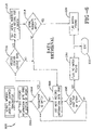
- FIG. 5 is an operational flow chart illustrating storage of transmitter serial numbers in the data structure
- FIG. 6 is an operational flow chart illustrating retrieval and confirmation of the transmitter serial numbers in the data structure.
- FIG. 7 is an operational flow chart illustrating erasure of selected records in the data structure.
- a garage door operator system which incorporates the concepts of the present invention is generally designated by the numeral 10 in FIG. 1 .
- the system 10 is employed in conjunction with a conventional sectional garage door generally indicated by the numeral 12 .
- the door 12 may or may not be an anti-pinch type door.
- the opening in which the door is positioned for opening and closing movements relative thereto is surrounded by a frame, generally indicated by the numeral 14 , which consists of a pair of a vertically spaced jamb members 16 that, as seen in FIG. 1 , are generally parallel and extend vertically upwardly from the ground.
- the jambs 16 are spaced and joined at their vertical upper extremity by a header 18 to thereby form a generally u-shaped frame 14 around the opening for the door 12 .
- the frame 14 is normally constructed of lumber or other structural building materials for the purpose of reinforcement and to facilitate the attachment of elements supporting and controlling the door 12 .
- L-shaped vertical members 20 Secured to the jambs 16 are L-shaped vertical members 20 which have a leg 22 attached to the jambs 16 and a projecting leg 24 which perpendicularly extends from respective legs 22 .
- the L-shaped vertical members 20 may also be provided in other shapes depending upon the particular frame and garage door with which it is associated.
- Secured to each projecting leg 24 is a track 26 which extends perpendicularly from each projecting leg 24 .
- Each track 26 receives a roller 28 which extends from the top edge of the garage door 12 . Additional rollers 28 may also be provided on each top vertical edge of each section of the garage door to facilitate transfer between opening and closing positions.
- a counterbalancing system generally indicated by the numeral 30 may be employed to balance the weight of the garage door 12 when moving between open and closed positions.
- a counterbalancing system is disclosed in U.S. Pat. No. 5,419,010, which is incorporated herein by reference.
- the counter-balancing system 30 includes a housing 32 , which is affixed to the header 18 and which contains an operator mechanism 34 best seen in FIG. 2 .
- Extending through the operator housing 32 is a drive shaft 36 , the opposite ends of which carry cable drums 38 that are affixed to respective projecting legs 24 .
- Carried within the drive shaft 36 are counterbalance springs as described in the '010 patent.
- the drive shaft 36 transmits the necessary mechanical power to transfer the garage door 12 between closed and open positions.
- the drive shaft 36 is coupled to a drive gear wherein the drive gear is coupled to a motor in a manner well known in the art.
- the counter-balancing system 30 may be controlled by a wireless remote transmitter 40 , which has a housing 41 , or a wall station control 42 , which has a housing 43 , that is wired directly to the system 30 or which may communicate via radio frequency or infrared signals.
- the wall station control 42 is likely to have additional operational features not present in the remote transmitter 40 .
- the housing 43 has a plurality of buttons thereon which may be associated with specific functional features.
- the system 30 may also be controlled by a keyless alphanumeric device 44 .
- the device 44 which may also be referred to as keypad, may include a display and a plurality of keys 46 with alphanumeric indicia thereon.
- Actuating the keys 46 in a predetermined sequence allows for actuation of the system 30 .
- the devices 40 , 42 and 44 are able to initiate opening and closing movements of the door coupled to the system 30 .
- the present invention is described in the context of a sectional garage door, the teachings of the invention are equally applicable to other types of movable barriers such as single panel doors, gates, windows, retractable overhangs and any device that at least partially encloses an area.
- An operator mechanism which is designated generally by the numeral 34 in FIG. 2 , is contained within the housing 32 and monitors operation of the motor and various other elements connected to the operator mechanism 34 as will be described hereinbelow. Independent power sources used to independently energize the operator and the transmitters.
- the operator mechanism 34 includes a controller 52 which incorporates the necessary software, hardware and memory storage devices for controlling the operation of the operator mechanism 34 .
- a controller 52 which incorporates the necessary software, hardware and memory storage devices for controlling the operation of the operator mechanism 34 .
- a non-volatile memory storage device 54 for permanently storing information utilized by the controller in conjunction with the operation of the operator mechanism 34 . It will be appreciated that it may be internally incorporated within the controller. It will further be appreciated that the memory device may be embodied in any type of computer-readable medium that is accessible by the controller 52 .
- Infrared and/or radio frequency signals are received by a receiver 56 which transmits the received information to a decoder contained within the controller.
- the controller 52 converts the received radio frequency signals or other types of wireless signals into a usable format.
- the controller 52 is capable of directly receiving transmission type signals from a direct wire source as evidenced by the direct connection to the wall station 42 .
- the keyless device 44 which may also be wireless, is also connected to the controller 52 . Any number of remote transmitters 40 a - x can transmit a signal that is received by the receiver 56 and further processed by the controller 52 as needed. Likewise, there can be any number of wall stations or keypad devices.
- the controller 52 If the input signals received from either the remote transmitter 40 , or the wall station control 42 or the keyless device 44 are acceptable, the controller 52 generates the appropriate electrical input signals for energizing the motor 60 which in turn rotates the drive shaft 36 and opens or closes the movable barrier.
- a light 62 which may be turned on and off independently or whenever an open/close cycle is initiated, may also be connected to the controller 52 .
- a memory array is designated generally by the numeral 60 , wherein the array is incorporated into the memory storage device 54 .
- the array 60 includes a plurality of records 62 , wherein the preferred embodiment provides twelve records. It will be appreciated that more or less records could be contained within the array.
- the array 60 is subdivided into groups designated generally by the numeral 64 wherein the array includes at least two groups although three are shown and more than three groups could be designated.
- the groups 64 are associated with the different types of transmitters that are capable of communicating with the controller 52 .
- the group 64 A which includes eight records, is set aside for all of the remote transmitters that can be associated with the operator system.
- Group 64 B is associated with the wall station transmitters, of which there are two, and group 64 C is associated with the keypad transmitters of which there are two. It will further be appreciated that the number of transmitters associated with each particular group may be adjusted and preferably there are at least two transmitters within each group.
- Each record has a plurality of bytes to be associated with a learned transmitter and a Record Information Byte designated in the drawing as RIB.
- the specific bits in each RIB are identified by an alphanumeric designation such as b 0 , b 1 , b 2 , b 3 , b 4 , b 5 , b 6 and b 7 .
- each of these specific bits is either a logical 0 or a logical 1 which may or may not be permanently designated.
- the array 60 may be initialized into the three groups in order to maintain separate record blocks for the unique transmitter types provided.
- the specific transmitter types stored in the RIB are associated with bits b 0 , b 1 and b 2 , and bits b 3 and b 4 may be reserved for additional transmitter types in a “bit test mode.” Or bits b 0 -b 4 of the RIB may be set aside for up to 32 unique transmitters in a “word test mode.”
- the RIB contains information about a learned transmitter that enables the data record to be accessed in an efficient manner and to allocate space when new information needs to be stored.
- bit test mode designated generally by the numeral 70 A. From this diagram it can be seen that the state or condition of the bits ( 1 or 0 ) in the RIB allows the controller to recognize a specific transmitter type. In other words, if the bit b 0 is designated as a 1, the controller reserves this data record for a remote transmitter. Accordingly, all the other bits b 1 -b 4 are designated as 0. This designation of bits reduces processing overhead but it does limit the number of transmitter types to the number of bits assigned for each transmitter type. Since, in this example, there are five bits; up to five transmitters can be assigned within an array. For example, bit b 3 may be reserved for hands-free transmitters which the controller recognizes depending upon the transmitter's proximity and direction of travel with respect to the controller.
- the word test mode uses a similar structure as the bit test mode, except that bits b 0 -b 4 are combined to make a transmitter type word.
- bits b 0 -b 4 are combined to make a transmitter type word.
- This method increases the processing overhead to determine the type of transmitter, but it increases the number of transmitter types with the least amount of RIB bits being used. Accordingly, with the five bits readily available for designation, up to thirty-two transmitter types can be assigned. It will further be appreciated that these thirty-two transmitter types may be grouped accordingly.
- Bit b 5 is designated for the purpose of determining whether a fixed code has been learned or not. In other words, if bit 5 is designated as “1” then a fixed code has been learned. If bit b 5 is designated as “0” then a fixed code has not been learned for that particular record.
- Bit b 6 designates whether or not an overwrite condition is allowed. In other words, if b 6 is set to 1 then that record is considered to be unwritable. If bit b 6 is set to 0 then the bit and the record is considered to be writable. Bit b 7 determines whether the record contains usable information.
- bit b 7 has a value of 1, then the record contains usable information and may not be erased. However, if bit b 7 has a value of 0, then the record contains unusable information and may be ignored. Initially, when the operator system is shipped from the factory, bits b 5 , b 6 and b 7 are set to the logic false condition or in other words, all are set to a value of 0. As different types of transmitters are learned to the controller, the conditions of b 5 -b 7 are adjusted accordingly.
- the controller 52 interacts with the array 60 to perform three primary functions. The first is data storage, the second is data retrieval, and the last is data erasure. These various data functions are described below in the context of the bit test mode, but it will be appreciated that they are equally applicable to the word test mode.
- a methodology for storing data in the memory array is designated generally by the numeral 100 .
- the controller is placed into a learn mode by any number of means such as actuation of a button associated with a controller or by the sending of a radio frequency signal to the controller that enables a learning mode.
- the learned transmitter is approved for use which allows for it to be used with the operating system.
- the controller 52 accesses the first record information bit at the bottom of the array which in this example is associated with record 12 .
- the controller inquires as to whether the transmitter identification received from the transmitter to be learned matches the transmitter identification of the particular record.
- the controller inquires from record 12 as to whether the transmitter bit b 2 in the corresponding RIB is designated as a 1 value. If not, then the process proceeds to step 106 and the next records's RIB in the array is obtained and step 104 is repeated. This repeating of steps 104 and 106 continues until a transmitter ID is matched. Accordingly, if a remote transmitter is being learned in this example, then a transmitter ID match will not occur until record 8 is queried. Once a transmitter ID match has been made, then the process continues to step 108 to determine whether the record contains usable data. In other words, the controller inquires as to whether bit b 7 of the corresponding is set to a 0 or a 1.
- bit b 7 is set to a 0 then the process continues step 108 . Since this record is available, then at step 110 , the learned transmitter is written to the memory array and in particular, a serial number associated with the new transmitter is stored in the record's bytes designated for that purpose. Next, at step 112 , the next available record with the same transmitter ID, which in this example would be record 7 , the bit b 6 is set equal to 0. In other words, the RIB of record 7 is designated as overwritable. At this time, the data storage procedure is exited at step 116 .
- Steps 108 through 116 are repeated, as needed, until all of the records within a group are filled with learned transmitters. It will be appreciated that over a period of time some transmitters may become lost or rendered inoperative and new transmitters may be learned. Accordingly, at some point in time all of the available records will contain usable data. This is tested at step 108 by determining whether bit b 7 is equal to 1. If bit b 7 for all of the records in the group is equal to 1, then upon attempting to learn a new transmitter, the process continues to step 118 to determine whether the record under evaluation is considered to be overwritable. In other words, the controller determines whether a record's RIB bit b 6 is equal to 1 or if it is equal to 0.
- step 106 If it is determined that bit b 6 is equal to 1, then the process continues to step 106 to obtain the next available record and the process repeats steps 104 and 108 .
- This loop of steps 118 , 106 , 104 and 108 continues within the group until the record that has bit b 6 equal to 0 is located which indicates that this particular record my be overwritten.
- steps 110 - 116 are executed as described above. Accordingly, the methodology 100 allows for learning of new transmitters and upon learning of each new transmitter, the record immediately adjacent the new learned record within that group is set to be overwritable. In this manner, when a new transmitter is learned, the next oldest transmitter is designated as being overwritable.
- a methodology for retrieving data from the memory array is designated generally by the numeral 200 .
- the controller is in an actual use mode and each transmitter transmission is checked to ensure that it is included in the memory array and approved for use with the controller.
- the controller upon receipt of a transmitter signal, the controller obtains the first record information byte at the bottom of the array.
- the controller determines whether the transmitter identification received matches the RIB found at the bottom of the array. If a match is not found, then at step 206 the next record information byte is accessed.
- an inquiry is made as to whether the sequence has passed the top of the array. If not, then the process returns to step 204 for repeating of that step. If, however, at step 208 it is determined that the controller has reached passed the top of the array, then at step 210 a flag “no match found” is designated and the process exits at step 212 .
- step 214 determines whether the RIB under scrutiny contains usable data or not. If the bit b 7 is equal to 1—usable data—then the serial number of the received transmission is tested at step 216 to determine whether it matches the serial number and related information stored in the associated data bytes. At step 218 if the serial number does not match, then the process returns to step 206 to obtain the next record information byte so that the steps 208 and 204 may be repeated. If at step 218 a serial number is matched with the record, then at step 220 a flag “match found” is set indicating that the serial number is stored within the record or associated therewith and that the controller may respond to the received command.
- step 214 If at step 214 it is determined that bit b 7 does not contain usable data—bit b 7 is at 0—then the process returns to step 206 to obtain the next record information byte.
- This data retrieval process effectively utilizes the memory array such that a memory pointer is not required and the overall processing of the signal is much faster and more reliable.
- a methodology for data erasure of selected bits in the records in the array is designated generally by the numeral 300 .
- the controller obtains the first record information bit at a bottom of the array.
- the controller marks this RIB as overwritable by setting the bit b 6 equal to 0.
- the record is designated as having unusable data by setting the bit b 7 equal to 0.
- the process proceeds to step 308 and the controller obtains the next record information bit. If at step 310 it is determined that the top of the array has not been reached then steps 304 , 306 and 308 are repeated.
- the data erasure process is exited.
- the data erasure process may be entered by holding a program button in for a predetermined period of time or by actuating the transmitter keys in a predetermined fashion.
- the data storage, retrieval, and erasure methodologies; and the structure of the data array provide numerous advantages.
- use of the data array in the manner described above eliminates the need for a memory record pointer.
- Such a data array provides sufficient memory to store a plurality of codes or records and allows for the recognition and storage of more than one unique type of transmitter device.
- the array's data structure is configured so that at least two records are set aside for wall stations and at least another two records are set aside for wireless keypads. It will be appreciated that the data structure is adaptable to handle a large number of records or codes and also allows for the simplification of code or record searching by the processing device. This allows for more valuable memory space to be utilized for other tasks associated with the use of the operating system.
Abstract
Description
Claims (19)
Priority Applications (1)
| Application Number | Priority Date | Filing Date | Title |
|---|---|---|---|
| US10/868,692 US7280031B1 (en) | 2004-06-14 | 2004-06-14 | Barrier operator system with enhanced transmitter storage capacity and related methods of storage and retrieval |
Applications Claiming Priority (1)
| Application Number | Priority Date | Filing Date | Title |
|---|---|---|---|
| US10/868,692 US7280031B1 (en) | 2004-06-14 | 2004-06-14 | Barrier operator system with enhanced transmitter storage capacity and related methods of storage and retrieval |
Publications (1)
| Publication Number | Publication Date |
|---|---|
| US7280031B1 true US7280031B1 (en) | 2007-10-09 |
Family
ID=38562147
Family Applications (1)
| Application Number | Title | Priority Date | Filing Date |
|---|---|---|---|
| US10/868,692 Expired - Fee Related US7280031B1 (en) | 2004-06-14 | 2004-06-14 | Barrier operator system with enhanced transmitter storage capacity and related methods of storage and retrieval |
Country Status (1)
| Country | Link |
|---|---|
| US (1) | US7280031B1 (en) |
Cited By (2)
| Publication number | Priority date | Publication date | Assignee | Title |
|---|---|---|---|---|
| US20100301999A1 (en) * | 2009-05-27 | 2010-12-02 | Overhead Door Corporation | Channel-switching remote controlled barrier opening system |
| US20120299697A1 (en) * | 2011-05-24 | 2012-11-29 | Mark Kenneth Siegesmund | Decryption of access codes of diverse protocols in barrier operator systems |
Citations (33)
| Publication number | Priority date | Publication date | Assignee | Title |
|---|---|---|---|---|
| US4228424A (en) | 1978-10-16 | 1980-10-14 | Baker Protective Services, Incorporated | Central station alarm |
| US4283710A (en) | 1978-10-25 | 1981-08-11 | J.S. Lock Company | Security system |
| US4529980A (en) | 1982-09-23 | 1985-07-16 | Chamberlain Manufacturing Corporation | Transmitter and receiver for controlling the coding in a transmitter and receiver |
| US4750118A (en) | 1985-10-29 | 1988-06-07 | Chamberlain Manufacturing Corporation | Coding system for multiple transmitters and a single receiver for a garage door opener |
| US4754255A (en) * | 1984-03-12 | 1988-06-28 | Sanders Rudy T | User identifying vehicle control and security device |
| US4772876A (en) | 1986-10-10 | 1988-09-20 | Zenith Electronics Corporation | Remote security transmitter address programmer |
| US4847542A (en) | 1987-10-22 | 1989-07-11 | Multi-Elmac Corporation | Automatic garage door operator with remote load control |
| US4851829A (en) * | 1986-12-04 | 1989-07-25 | Motorola, Inc. | Paging receiver with alert indicating status of memory |
| US4855713A (en) | 1988-10-07 | 1989-08-08 | Interactive Technologies, Inc. | Learn mode transmitter |
| US4881148A (en) | 1987-05-21 | 1989-11-14 | Wickes Manufacturing Company | Remote control system for door locks |
| US5077547A (en) | 1990-03-06 | 1991-12-31 | Dicon Systems Limited | Non contact programming for transmitter module |
| US5097505A (en) | 1989-10-31 | 1992-03-17 | Securities Dynamics Technologies, Inc. | Method and apparatus for secure identification and verification |
| US5146215A (en) * | 1987-09-08 | 1992-09-08 | Clifford Electronics, Inc. | Electronically programmable remote control for vehicle security system |
| US5148159A (en) | 1989-04-26 | 1992-09-15 | Stanley Electronics | Remote control system with teach/learn setting of identification code |
| US5252960A (en) | 1991-08-26 | 1993-10-12 | Stanley Home Automation | Secure keyless entry system for automatic garage door operator |
| US5291193A (en) | 1988-01-21 | 1994-03-01 | Matsushita Electric Works, Ltd. | Identification registration for a wireless transmission-reception control system |
| US5349345A (en) | 1992-06-30 | 1994-09-20 | Vindicator Corporation | Electronic lock |
| US5408217A (en) | 1994-03-21 | 1995-04-18 | Sanconix, Inc. | Secure fire/security/sensor transmitter system |
| US5473318A (en) | 1992-01-10 | 1995-12-05 | Active Control Technology Inc. | Secure remote control system with receiver controlled to add and delete identity codes |
| USRE35364E (en) | 1985-10-29 | 1996-10-29 | The Chamberlain Group, Inc. | Coding system for multiple transmitters and a single receiver for a garage door opener |
| US5576701A (en) | 1990-07-16 | 1996-11-19 | The Chamberlain Group, Inc. | Remote actuating apparatus comprising keypad controlled transmitter |
| US5635913A (en) | 1990-07-16 | 1997-06-03 | The Chamberlain Group, Inc. | Remote actuating apparatus with long and short operating codes |
| US5751224A (en) | 1995-05-17 | 1998-05-12 | The Chamberlain Group, Inc. | Code learning system for a movable barrier operator |
| US5781143A (en) | 1996-02-06 | 1998-07-14 | Rossin; John A. | Auto-acquire of transmitter ID by receiver |
| US5854593A (en) | 1996-07-26 | 1998-12-29 | Prince Corporation | Fast scan trainable transmitter |
| US5872513A (en) * | 1996-04-24 | 1999-02-16 | The Chamberlain Group, Inc. | Garage door opener and wireless keypad transmitter with temporary password feature |
| US5907288A (en) | 1997-05-14 | 1999-05-25 | Clark; David P. | Access code processing for a security system |
| US5945936A (en) | 1996-10-18 | 1999-08-31 | Issa; Darrell | Learn mode for remote transmitters |
| US6049289A (en) | 1996-09-06 | 2000-04-11 | Overhead Door Corporation | Remote controlled garage door opening system |
| US6181255B1 (en) | 1997-02-27 | 2001-01-30 | The Chamberlain Group, Inc. | Multi-frequency radio frequency transmitter with code learning capability |
| US6414587B1 (en) | 1998-03-13 | 2002-07-02 | The Chamberlain Group, Inc. | Code learning system for a movable barrier operator |
| US20030214385A1 (en) * | 2002-05-20 | 2003-11-20 | Wayne-Dalton Corp. | Operator with transmitter storage overwrite protection and method of use |
| US6847287B1 (en) * | 2001-06-11 | 2005-01-25 | Linear Corporation | Transmitter-receiver control system for an actuator and method |
-
2004
- 2004-06-14 US US10/868,692 patent/US7280031B1/en not_active Expired - Fee Related
Patent Citations (36)
| Publication number | Priority date | Publication date | Assignee | Title |
|---|---|---|---|---|
| US4228424A (en) | 1978-10-16 | 1980-10-14 | Baker Protective Services, Incorporated | Central station alarm |
| US4283710A (en) | 1978-10-25 | 1981-08-11 | J.S. Lock Company | Security system |
| US4529980A (en) | 1982-09-23 | 1985-07-16 | Chamberlain Manufacturing Corporation | Transmitter and receiver for controlling the coding in a transmitter and receiver |
| US4754255A (en) * | 1984-03-12 | 1988-06-28 | Sanders Rudy T | User identifying vehicle control and security device |
| USRE36703E (en) | 1984-05-30 | 2000-05-16 | The Chamberlain Group, Inc. | Coding system for multiple transmitters and a single receiver for a garage door opener |
| USRE37986E1 (en) | 1984-05-30 | 2003-02-11 | The Chamberlain Group, Inc. | Coding system for multiple transmitters and a single receiver |
| US4750118A (en) | 1985-10-29 | 1988-06-07 | Chamberlain Manufacturing Corporation | Coding system for multiple transmitters and a single receiver for a garage door opener |
| USRE35364E (en) | 1985-10-29 | 1996-10-29 | The Chamberlain Group, Inc. | Coding system for multiple transmitters and a single receiver for a garage door opener |
| US4772876A (en) | 1986-10-10 | 1988-09-20 | Zenith Electronics Corporation | Remote security transmitter address programmer |
| US4851829A (en) * | 1986-12-04 | 1989-07-25 | Motorola, Inc. | Paging receiver with alert indicating status of memory |
| US4881148A (en) | 1987-05-21 | 1989-11-14 | Wickes Manufacturing Company | Remote control system for door locks |
| US5146215A (en) * | 1987-09-08 | 1992-09-08 | Clifford Electronics, Inc. | Electronically programmable remote control for vehicle security system |
| US4847542A (en) | 1987-10-22 | 1989-07-11 | Multi-Elmac Corporation | Automatic garage door operator with remote load control |
| US5291193A (en) | 1988-01-21 | 1994-03-01 | Matsushita Electric Works, Ltd. | Identification registration for a wireless transmission-reception control system |
| US4855713A (en) | 1988-10-07 | 1989-08-08 | Interactive Technologies, Inc. | Learn mode transmitter |
| US5148159A (en) | 1989-04-26 | 1992-09-15 | Stanley Electronics | Remote control system with teach/learn setting of identification code |
| US5097505A (en) | 1989-10-31 | 1992-03-17 | Securities Dynamics Technologies, Inc. | Method and apparatus for secure identification and verification |
| US5077547A (en) | 1990-03-06 | 1991-12-31 | Dicon Systems Limited | Non contact programming for transmitter module |
| US5635913A (en) | 1990-07-16 | 1997-06-03 | The Chamberlain Group, Inc. | Remote actuating apparatus with long and short operating codes |
| US5576701A (en) | 1990-07-16 | 1996-11-19 | The Chamberlain Group, Inc. | Remote actuating apparatus comprising keypad controlled transmitter |
| US5252960A (en) | 1991-08-26 | 1993-10-12 | Stanley Home Automation | Secure keyless entry system for automatic garage door operator |
| US5473318A (en) | 1992-01-10 | 1995-12-05 | Active Control Technology Inc. | Secure remote control system with receiver controlled to add and delete identity codes |
| US5349345A (en) | 1992-06-30 | 1994-09-20 | Vindicator Corporation | Electronic lock |
| US5408217A (en) | 1994-03-21 | 1995-04-18 | Sanconix, Inc. | Secure fire/security/sensor transmitter system |
| US6081203A (en) | 1995-05-17 | 2000-06-27 | Chamberlain Group, Inc. | Code learning system for a movable barrier operator |
| US5751224A (en) | 1995-05-17 | 1998-05-12 | The Chamberlain Group, Inc. | Code learning system for a movable barrier operator |
| US5781143A (en) | 1996-02-06 | 1998-07-14 | Rossin; John A. | Auto-acquire of transmitter ID by receiver |
| US5872513A (en) * | 1996-04-24 | 1999-02-16 | The Chamberlain Group, Inc. | Garage door opener and wireless keypad transmitter with temporary password feature |
| US5854593A (en) | 1996-07-26 | 1998-12-29 | Prince Corporation | Fast scan trainable transmitter |
| US6049289A (en) | 1996-09-06 | 2000-04-11 | Overhead Door Corporation | Remote controlled garage door opening system |
| US5945936A (en) | 1996-10-18 | 1999-08-31 | Issa; Darrell | Learn mode for remote transmitters |
| US6181255B1 (en) | 1997-02-27 | 2001-01-30 | The Chamberlain Group, Inc. | Multi-frequency radio frequency transmitter with code learning capability |
| US5907288A (en) | 1997-05-14 | 1999-05-25 | Clark; David P. | Access code processing for a security system |
| US6414587B1 (en) | 1998-03-13 | 2002-07-02 | The Chamberlain Group, Inc. | Code learning system for a movable barrier operator |
| US6847287B1 (en) * | 2001-06-11 | 2005-01-25 | Linear Corporation | Transmitter-receiver control system for an actuator and method |
| US20030214385A1 (en) * | 2002-05-20 | 2003-11-20 | Wayne-Dalton Corp. | Operator with transmitter storage overwrite protection and method of use |
Cited By (8)
| Publication number | Priority date | Publication date | Assignee | Title |
|---|---|---|---|---|
| US20100301999A1 (en) * | 2009-05-27 | 2010-12-02 | Overhead Door Corporation | Channel-switching remote controlled barrier opening system |
| US8581695B2 (en) | 2009-05-27 | 2013-11-12 | Grant B. Carlson | Channel-switching remote controlled barrier opening system |
| US8970345B2 (en) | 2009-05-27 | 2015-03-03 | Overhead Door Corporation | Channel-switching remote controlled barrier opening system |
| US9483935B2 (en) | 2009-05-27 | 2016-11-01 | Overhead Door Corporation | Channel-switching remote controlled barrier opening system |
| US20120299697A1 (en) * | 2011-05-24 | 2012-11-29 | Mark Kenneth Siegesmund | Decryption of access codes of diverse protocols in barrier operator systems |
| US9388621B2 (en) * | 2011-05-24 | 2016-07-12 | Overhead Door Corporation | Decryption of access codes of diverse protocols in barrier operator systems |
| US10060173B2 (en) | 2011-05-24 | 2018-08-28 | Overhead Door Corporation | Multiple speed profiles in barrier operator systems |
| US10096189B2 (en) | 2011-05-24 | 2018-10-09 | Overhead Door Corporation | Decryption of access codes of diverse protocols in barrier operator systems |
Similar Documents
| Publication | Publication Date | Title |
|---|---|---|
| EP1495450B1 (en) | Operator with transmitter storage overwrite protection and method of use | |
| US8228165B2 (en) | Radio receiver and transmitter apparatus for radio-controlled automation systems for opening/closure | |
| US6963267B2 (en) | Operator for a movable barrier and method of use | |
| US20080061926A1 (en) | Method and apparatus for utilizing a transmitter having a range limitation to control a movable barrier operator | |
| GB2312539A (en) | Allowing barrier movement activation according to user access code type | |
| US7173514B2 (en) | Operator for a movable barrier and method of use | |
| US7525412B2 (en) | System and method for performing transmitter function mapping | |
| CZ20031608A3 (en) | Remote control device and assembly method of such remote control device | |
| US7375612B2 (en) | Systems and related methods for learning a radio control transmitter to an operator | |
| GB2399203A (en) | Security code learning | |
| CA2579952A1 (en) | Barrier operator with secure/unsecure transmitter and method of use | |
| US7280031B1 (en) | Barrier operator system with enhanced transmitter storage capacity and related methods of storage and retrieval | |
| US8618907B2 (en) | Method and apparatus for coding identification information into a security transmission and method and apparatus for automatic learning of replacement security codes | |
| US6847287B1 (en) | Transmitter-receiver control system for an actuator and method | |
| CA2519215C (en) | Closing system and method for operating same | |
| JP4488495B2 (en) | Entrance / exit management system | |
| JP4174156B2 (en) | Control signal receiver for switchgear | |
| US20110199181A1 (en) | Coded remote controller and means to secure entry | |
| JP2004124628A (en) | Security system |
Legal Events
| Date | Code | Title | Description |
|---|---|---|---|
| AS | Assignment |
Owner name: WAYNE-DALTON CORP., OHIO Free format text: ASSIGNMENT OF ASSIGNORS INTEREST;ASSIGNORS:RODRIGUEZ, YAN;GAGNON, RICHARD E.;REEL/FRAME:015480/0648;SIGNING DATES FROM 20040603 TO 20040609 |
|
| STCF | Information on status: patent grant |
Free format text: PATENTED CASE |
|
| FEPP | Fee payment procedure |
Free format text: PAT HOLDER CLAIMS SMALL ENTITY STATUS, ENTITY STATUS SET TO SMALL (ORIGINAL EVENT CODE: LTOS); ENTITY STATUS OF PATENT OWNER: SMALL ENTITY |
|
| AS | Assignment |
Owner name: HOMERUN HOLDINGS CORP., OHIO Free format text: CHANGE OF NAME;ASSIGNOR:WAYNE-DALTON CORP.;REEL/FRAME:025744/0204 Effective date: 20091217 |
|
| FPAY | Fee payment |
Year of fee payment: 4 |
|
| AS | Assignment |
Owner name: HRH NEWCO CORPORATION, FLORIDA Free format text: ASSIGNMENT OF ASSIGNORS INTEREST;ASSIGNOR:HOMERUN HOLDINGS CORP.;REEL/FRAME:026010/0671 Effective date: 20110322 |
|
| AS | Assignment |
Owner name: HOMERUN HOLDINGS CORPORATION, FLORIDA Free format text: CHANGE OF NAME;ASSIGNOR:HRH NEWCO CORPORATION;REEL/FRAME:026114/0102 Effective date: 20101105 |
|
| FPAY | Fee payment |
Year of fee payment: 8 |
|
| FEPP | Fee payment procedure |
Free format text: MAINTENANCE FEE REMINDER MAILED (ORIGINAL EVENT CODE: REM.); ENTITY STATUS OF PATENT OWNER: SMALL ENTITY |
|
| LAPS | Lapse for failure to pay maintenance fees |
Free format text: PATENT EXPIRED FOR FAILURE TO PAY MAINTENANCE FEES (ORIGINAL EVENT CODE: EXP.); ENTITY STATUS OF PATENT OWNER: SMALL ENTITY |
|
| STCH | Information on status: patent discontinuation |
Free format text: PATENT EXPIRED DUE TO NONPAYMENT OF MAINTENANCE FEES UNDER 37 CFR 1.362 |
|
| FP | Lapsed due to failure to pay maintenance fee |
Effective date: 20191009 |