US7685494B1 - Error correction coding for varying signal-to-noise ratio channels - Google Patents
Error correction coding for varying signal-to-noise ratio channels Download PDFInfo
- Publication number
- US7685494B1 US7685494B1 US11/745,254 US74525407A US7685494B1 US 7685494 B1 US7685494 B1 US 7685494B1 US 74525407 A US74525407 A US 74525407A US 7685494 B1 US7685494 B1 US 7685494B1
- Authority
- US
- United States
- Prior art keywords
- snr
- codeword
- error correction
- portions
- domains
- Prior art date
- Legal status (The legal status is an assumption and is not a legal conclusion. Google has not performed a legal analysis and makes no representation as to the accuracy of the status listed.)
- Active, expires
Links
Images


Classifications
-
- H—ELECTRICITY
- H03—ELECTRONIC CIRCUITRY
- H03M—CODING; DECODING; CODE CONVERSION IN GENERAL
- H03M13/00—Coding, decoding or code conversion, for error detection or error correction; Coding theory basic assumptions; Coding bounds; Error probability evaluation methods; Channel models; Simulation or testing of codes
- H03M13/03—Error detection or forward error correction by redundancy in data representation, i.e. code words containing more digits than the source words
- H03M13/05—Error detection or forward error correction by redundancy in data representation, i.e. code words containing more digits than the source words using block codes, i.e. a predetermined number of check bits joined to a predetermined number of information bits
- H03M13/11—Error detection or forward error correction by redundancy in data representation, i.e. code words containing more digits than the source words using block codes, i.e. a predetermined number of check bits joined to a predetermined number of information bits using multiple parity bits
- H03M13/1102—Codes on graphs and decoding on graphs, e.g. low-density parity check [LDPC] codes
- H03M13/1148—Structural properties of the code parity-check or generator matrix
-
- H—ELECTRICITY
- H03—ELECTRONIC CIRCUITRY
- H03M—CODING; DECODING; CODE CONVERSION IN GENERAL
- H03M13/00—Coding, decoding or code conversion, for error detection or error correction; Coding theory basic assumptions; Coding bounds; Error probability evaluation methods; Channel models; Simulation or testing of codes
- H03M13/03—Error detection or forward error correction by redundancy in data representation, i.e. code words containing more digits than the source words
- H03M13/033—Theoretical methods to calculate these checking codes
-
- H—ELECTRICITY
- H03—ELECTRONIC CIRCUITRY
- H03M—CODING; DECODING; CODE CONVERSION IN GENERAL
- H03M13/00—Coding, decoding or code conversion, for error detection or error correction; Coding theory basic assumptions; Coding bounds; Error probability evaluation methods; Channel models; Simulation or testing of codes
- H03M13/03—Error detection or forward error correction by redundancy in data representation, i.e. code words containing more digits than the source words
- H03M13/05—Error detection or forward error correction by redundancy in data representation, i.e. code words containing more digits than the source words using block codes, i.e. a predetermined number of check bits joined to a predetermined number of information bits
- H03M13/11—Error detection or forward error correction by redundancy in data representation, i.e. code words containing more digits than the source words using block codes, i.e. a predetermined number of check bits joined to a predetermined number of information bits using multiple parity bits
- H03M13/1102—Codes on graphs and decoding on graphs, e.g. low-density parity check [LDPC] codes
-
- H—ELECTRICITY
- H03—ELECTRONIC CIRCUITRY
- H03M—CODING; DECODING; CODE CONVERSION IN GENERAL
- H03M13/00—Coding, decoding or code conversion, for error detection or error correction; Coding theory basic assumptions; Coding bounds; Error probability evaluation methods; Channel models; Simulation or testing of codes
- H03M13/35—Unequal or adaptive error protection, e.g. by providing a different level of protection according to significance of source information or by adapting the coding according to the change of transmission channel characteristics
- H03M13/353—Adaptation to the channel
Definitions
- Error correction coding techniques have been commonly used to reduce errors introduced during digital data transmission or storage. Prior to transmission, for example, each piece of data, such as a 16 bit word, may be encoded to incorporate additional information so that upon reception, the data may be recovered even when errors are introduced during transit between transmitter and receiver.
- LDPC codes are linear binary block codes whose codewords satisfy a set of M linear parity-check constraints. LDPC codes were largely forgotten after their initial disclosure due to lack of computing power, but were revived in the mid 1990's and have since been recognized to offer better performance and less decoding complexity than many later disclosed error correcting codes.
- An LDPC code is defined by a sparse M ⁇ N parity-check binary matrix (LDPC matrix).
- a regular LDPC code has an LDPC matrix in which each of its rows have the same number k of ones (1s), and each of the columns have the same number j of 1s, where j ⁇ k.
- An irregular LDPC code has an LDPC matrix in which not all rows and columns have the same number of 1s.
- the irregular LDPC code is applied in an error rate sensitive error correction (ERSEC) system disclosed herein that improves error correction effectiveness by allocating error correction resources based on error susceptibility.
- ERSEC error rate sensitive error correction
- SNR signal-to-noise ratio
- different measures may be more appropriate than SNR.
- the SNR When applied to a communication channel, the SNR may be determined, estimated, or detected to be different for different portions of a data stream so that errors may be more likely to be introduced in one portion of the data stream than other portions.
- the ERSEC system may allocate more robust error correction coding to those portions of the data transmission that may experience lower SNRs than other portions.
- the ERSEC system may encode data that is expected to experience lower SNR with greater error correction capability in an irregular LDPC, for example, than other portions for which higher SNRs are expected.
- a storage medium application such as an optical disc (e.g., CD, DVD, holographic optical disc, etc.)
- different portions of the optical disc medium may be more error prone than other portions due to the physics of the read/write mechanisms or the materials of a particular optical disc, for example.
- the SNRs for different portions of the optical disc may be predetermined based on the optical disc/disc drive design, estimated based on past experience or detected by tests that determine bit-error-rates (BERs), for example.
- BERs bit-error-rates
- the recorded bit stream may be written in tracks that extend through different SNR regions or domains.
- the ERSEC system may encode the data bits with error correction capabilities that match the SNRs of the domains which the data bits are expected to experience.
- the ERSEC system applies error correction resources adaptively with efficient use of resources to obtain low BERs.
- FIG. 1 shows an exemplary block diagram of an error rate sensitive error correction (ERSEC) system
- FIG. 2 shows an example of an ERSEC system transmission over a communication channel
- FIG. 3 shows an exemplary block diagram of SNR detection for adaptive encoding
- FIG. 4 shows an exemplary holographic recording system
- FIG. 5 shows an exemplary holographic retrieval system
- FIG. 6 shows an exemplary SNR profile for a holographic page
- FIG. 7 shows an exemplary two-dimensional image pixels arranged in a matrix format
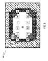
- FIG. 8 shows an exemplary mapping of the two dimensional image pixels onto a holographic page
- FIG. 9 shows an exemplary table showing a mapping of the two dimensional image pixels onto SNR domains of a holographic page
- FIG. 10 shows an exemplary table showing adaptive application of error correction coding to the two dimensional image pixels based on the SNR domains
- FIG. 11 shows a first exemplary parity-check matrix and a corresponding Tanner graph
- FIG. 12 shows an exemplary diagram of an iterative message passing decoding process
- FIG. 13 shows an exemplary ERSEC system employing Low-Density Parity-Check (LDPC) encoding and decoding.
- LDPC Low-Density Parity-Check
- FIG. 14 shows a first exemplary pixel-to-variable node-mapping scheme
- FIG. 15 shows a second exemplary parity-check matrix and a corresponding Tanner graph
- FIG. 16 shows the first exemplary pixel-to-variable node-mapping scheme with the second exemplary parity-check matrix
- FIG. 17 shows a second exemplary pixel-to-variable node mapping scheme with the second exemplary parity-check matrix
- FIG. 18 shows an exemplary density evolution optimization processor
- FIG. 19 shows a block diagram of an exemplary ERSEC system
- FIG. 20 shows a flow chart showing an exemplary encoder/decoder parameter update process
- FIG. 21 shows a flow chart showing an exemplary encoding process
- FIG. 22 shows a flow chart showing an exemplary decoding process.
- FIG. 1 shows an exemplary block diagram of an error rate sensitive error correction (ERSEC) system 100 that includes an encoder 102 and a decoder 106 .
- Codewords output from encoder 102 are transmitted through a channel 104 , received at decoder 106 as received codewords, decoded and outputted from decoder 106 as decoded data that corresponds to input data received by encoder 102 .
- ERSEC system 100 sets parameters in encoder 102 and decoder 106 to protect different portions of the input data with different levels of error correction coding based on error susceptibility of each portion.
- channel is used broadly to include communication channels such as digital wired or wireless communications over a network, for example, as well as any other system or device through which data is passed between encoder 102 and decoder 104 .
- Data storage devices are channels within this broad meaning, for example.
- data may be encoded by encoder 102 , stored on a storage medium, later retrieved from the storage medium, and decoded by decoder 106 .
- FIG. 2 shows an example of ERSEC system operation in a communication environment 110 using transmission media such as microwave, coaxial cable, computer network, satellite, etc.
- a baseband protocol is used as an example where binary codewords “a” and “a+1” are transmitted in blocks of ones (1s) and zeros (0s) indicated as V 1 , V 2 , . . . Bits V 1 -V 3 are expected to experience SNR 1 , V 4 is expected to experience SNR 2 , and V 5 -V 8 are expected to experience SNR 3 , where SNR 1 >SNR 2 >SNR 3 , for example.
- ERSEC system 100 sets parameters of encoder 102 to encode V 1 -V 3 using a low level of error correction, V 4 using a medium level of error correction, and V 5 -V 8 using a high level of error correction so that the BER of the transmission over channel 104 is reduced when compared to applying a constant level of error correction that corresponds to an average SNR for channel 104 , for example.
- the SNR profile may be estimated for a particular channel.
- the SNR for each portion of a data transmission may be affected by known mechanisms that are dependent on the position of bits in particular locations within a codeword.
- a clock signal is often retrieved from the received bits, and depending on a particular clock retrieval scheme, different bits in a data stream may be more or less susceptible to reception error.
- an SNR profile may be estimated for each bit position of a data stream for the entire transit from encoder 102 to decoder 104 .
- FIG. 3 shows an exemplary SNR detection system 120 that includes an SNR detector 122 and an encoder 124 . Based on BERs obtained using the test data streams, SNR detector 122 may generate an SNR profile and send it to encoder 124 for updating assignment of error correction levels to codeword bits, for example.
- SNR detector 122 may be part of a communication network such as a base station for cell phone communications, for example. Alternatively, SNR detector 122 may be incorporated in encoder 124 , so that periodically, encoder 124 may execute an error correction level update cycle to “sample” a current SNR profile. In this way, encoder 124 may adapt to changing SNR environment to achieve a lower BER than non-adaptive error correction systems.
- the SNR profile may be determined by the manufacturer and stored in the storage medium, or determined by a recording device prior to recording, for example. Similar to determining bad portions of a magnetic disk where 1s are written over portions of tracks that have non-usable portions, a recording device may write and then read test data for a specific media and determine the SNR profile. A dedicated portion of the storage media may be set aside to storing error correction parameters where the SNR profile, encoding, and/or decoding parameters may be store as a look-up table, for example.
- FIG. 4 shows an example of a holographic storage system that includes a spatial light modulator (SLM) 206 which is illumined by a laser beam 200 to form a data beam 201 .
- SLM spatial light modulator
- Data beam 201 illuminates a recording medium 204 at a selected writing location.
- the same writing location is also illuminated by one of many reference beams 202 directed at a particular angle to form an interference pattern that is recorded in recording medium 204 as a hologram.
- a first set of multiple original pages 208 may be stored as holograms at the same selected writing location of SLM 206 , where each of the first set of original pages 208 are stored using a different one of reference beams 202 directed at a unique angle, for example. After all of reference beams 202 are used, an adjacent writing location may be selected for recording a next set of original pages 208 (e.g., Pm, Pm+1, . . . ).
- recorded pages may be retrieved by illuminating recording medium 204 with one of reference beams 202 at a selected reading location and the writing angle to generate data beam 203 that is imaged onto a sensor 212 such as a photodetector array, for example.
- Sensor 212 converts data beam 203 into a page, and after multiple conversions, sets of received pages 214 (e.g., Pr ⁇ Ps ⁇ 1; Ps, Ps+1, . . . ) are formed.
- Recorded holograms of different reference beams 202 and holograms of adjacent writing locations may introduce errors when reading a page from recording medium 204 .
- Such susceptibility to errors may be represented by one or more SNRs.
- SNRs For example, an SNR of a central portion of a page may be higher than at page edges, and worst at page corners due to influence of three adjacent pages.
- an SNR profile may be generated based on BERs of different positions within a page.
- FIG. 6 shows an exemplary SNR profile for a page 300 in recording medium 204 . While the SNR may vary in a continuous manner across page 300 , FIG. 6 shows an SNR profile having three domains 302 , 304 and 306 as an example, where a single average SNR is assigned to each domain 302 - 306 . The presence of numerous SNR values within page 300 may be accounted for by defining contours of domains 302 - 306 based on a range of SNR values, or defining the contours of domains 302 - 306 by an SNR tolerance value (i.e., ⁇ 5.0%).
- SNR tolerance value i.e., ⁇ 5.0%
- domain 302 is associated with SNR 1
- domain 304 is associated with SNR 2
- domain 306 is associated with SNR 3
- SNR 1 >SNR 2 >SNR 3 This SNR profile may be stored in recording medium 204 at a predetermined location so that recording devices implementing the ERSEC system may access the SNR profile to encode data with different error correction levels according to expected error rates based on the SNR profile.
- FIG. 7 shows a two-dimensional pixel image 310 that is to be written into page 300 .
- Pixel image 310 may be an image of a document page or a video frame of a movie, for example.
- pixel image 310 is shown to include information that corresponds to 32 pixels arranged in a matrix format instead of a 1024 ⁇ 768 matrix image of 786,432 pixels of a computer screen, for example.
- pixel image 310 is a Red-Green-Blue (RGB) color image
- RGB Red-Green-Blue
- each pixel may be represented by three 8-bit values forming a 24-bit unit of information.
- each row of 8 pixels may be represented by 192 bits
- pixel image 310 may be represented by 768 bits.
- FIG. 8 shows page 300 when written with pixel image 310 .
- Pixels 1 - 8 , 9 , 16 , 17 , 24 , and 25 - 32 are written into domain 306 ;
- pixels 10 , 15 , 18 and 23 are written into domain 304 ;
- pixels 11 - 14 and 19 - 22 are written into domain 302 .
- This correspondence between pixels 1 - 32 and domains 302 - 306 may be saved in a table such as table 322 shown in FIG. 9 .
- ERSEC system 100 may assign error correction coding levels shown in FIG. 10 , if Hamming coding is used, for example.
- pixels to be written in domain 306 may be assigned a high level 3 bit error correction coding (ECC); pixels to be written in domain 304 may be assigned a medium level 2 bit ECC; and pixels to be written in domain 302 may be assigned a low level 1 bit ECC.
- ECC error correction coding
- the specific levels of ECC are shown as an example. In actual implementations, other appropriate values may be used based on actual SNR profiles, domain contours, available processing power, specific error correction coding techniques, etc.
- the different levels of error correction coding may also be implemented using different coding techniques for some or all of the levels.
- three codes can be prepared for different SNRs: Code 1, Code 2, Code 3, where Code 1 has greater correction capability than Codes 2 and 3, and Code 2 has greater correction capability than Code 3.
- Code 1 can be used in regions where low SNR is detected/estimated, Code 2 in regions where medium SNR is detected/estimated and Code 3 in regions where high SNR is detected/estimated.
- pixels to be written to domain 306 may be assign a Code 1 error correction coding
- pixels written to domain 304 may be assigned a Code 2 error correction coding
- pixels to be written to domain 302 may be assigned a Code 3 error correction coding.
- LDPC codes which are linear block codes that includes sparse parity check matrices (H).
- the H-matrix is not unique and thus, for any specific application, an appropriate H-matrix may be selected. As discussed below, an H-matrix may be selected so that a mixture of variable node degrees is consistent with desired levels of error correction.
- H ⁇ received-codeword may not equal to 0.
- an iterative message passing decoding process may be performed that can correct errors in the received-codeword so that the input data may be recovered within an acceptable level of confidence.
- FIG. 11 shows an example H-matrix 400 to facilitate discussion.
- H-matrix 400 is not an actual H-matrix because an actual H-matrix is sparse which means that a number of 1s in each row and the number of 1s in each column are small compared to the number of rows in the actual H-matrix, for example.
- H-matrix 400 may be represented as a Tanner graph 402 , where variable nodes 404 , indicated as V 1 -V 8 , represent bits of the receive-codeword and correspond to columns of H-matrix 400 .
- Check nodes 408 correspond to rows of H-matrix 400 .
- Edges 406 connect each variable node 404 with at least one of check nodes 408 as indicated by row positions of the 1s in the column that corresponds to each variable node 404 .
- a number of edges 406 connected to a variable node 404 is referred to as a degree of the variable node 404 .
- variable node V 1 has a degree of 3
- variable node V 2 has a degree of 2
- variable node V 3 has a degree of 1, and so on.
- the error correction capability that corresponds to a variable node 404 typically increases as the degree of that variable node 404 increases.
- ERSEC system 100 assigns bits of a codeword that require greater error correction capacity to variable nodes 404 that have greater degrees.
- FIG. 12 shows a diagram 420 of the iterative message passing process mentioned above that follows the process for check node C 1 and variable V 1 for one iteration.
- the process is an exemplary description of a hard decoding algorithm, and is as follows:
- variable nodes V 1 -V 8 are loaded with corresponding bits of a received-codeword. For example, if the received-codeword is 11010011, then V 1 is set to a 1, V 2 is set to a 1, V 3 is set to a 0, V 4 is set to a 1, V 5 is set to a 0, V 6 is set to a 0, V 7 is set to a 1, and V 8 is set to a 1;
- each variable node 404 evaluates a correct value of the originally transmitted codeword bit that corresponds to the variable node 404 .
- the received-codeword bit that is loaded is assumed to be the correct value.
- each variable node 404 may simply return to connected check nodes 408 a value that is received from a larger number of connected check nodes 408 after execution of a step 2 described below.
- the evaluated correct value is sent via a message to check nodes 408 that are connected by an edge 406 to each variable node 404 .
- V 1 , V 3 , V 5 , V 6 , and V 8 sends 1, 0, 0, 0, and 1, respectively to check node C 1 ;
- each check node 408 evaluates for each connected variable node 404 , a value that the variable node 404 must have to achieve correct parity (even parity, for example) based on the variable node values sent to the check node 408 by all other variable nodes 404 that are connected to the check node 408 .
- the values determined in this way are known as extrinsic messages, as they are based on the information from all neighboring nodes except the one to which the information is returned.
- the determined extrinsic value (which are not necessarily the same) for each of the variable nodes 404 is returned to each of the connected variable nodes.
- the values sent back to the variable nodes V 1 , V 3 , V 5 , V 6 , and V 8 are: 1, 0, 0, 0, 1, respectively; and
- Steps 1 and 2 are repeated until a confidence level exceeds a predetermined value which indicates that the value for each of the variable nodes 404 is correct, or until a predefined number of decoding iterations is reached.
- the originally loaded values for V 1 , V 3 , V 5 , V 6 , and V 8 appear to be correct and the process ends in only one cycle (iteration) if based only on the operation of check node C 1 .
- Tanner graph 402 includes many more edges 406 and check nodes 408 , and the result of all the check nodes 408 must exceed the required confidence level before the iterations of steps 1 and 2 can be stopped.
- a “soft-decision” may be used in which probability mass function (PMF) (i.e., the probabilities whether a bit-value is a 1 or a 0) is used.
- PMF probability mass function
- PMF the probabilities whether a bit-value is a 1 or a 0
- PMF probability mass function
- the initial PMFs loaded into variable nodes 404 may be determined based on the received real-values and on an SNR and other channel characteristics, for example.
- Check nodes 408 calculates PMFs for each of the connected variable nodes 404 (i.e., the PMFs of whether the value of each variable node 404 should be a 1 or a 0).
- the extrinsic PMFs calculated by check nodes 408 can be sent back to variable nodes 404 . These PMFs can then be used to compute the new PMFs that are sent back to check nodes, and so on.
- the decoding procedure stops when the PDFs for the values of all variable nodes 404 exceed a threshold value or confidence level or when the maximum (predefined) number of iterations is reached.
- FIG. 13 shows a block diagram of an exemplary ERSEC system 450 using LDPC coding that includes an encoder 452 , a channel 454 and a decoder 456 .
- channel 454 may include any medium or device that data must transit between encoder 452 and decoder 456 .
- Encoder 452 receives original input data m, and generates codewords for each block of input data by performing matrix multiplication as shown in equation (1). The codewords are transmitted over channel 454 , received at decoder 456 as received-codewords, and decoded by first performing the iterative message passing process described above to obtain retrieved-codewords, and decoding the retrieved-codewords into decoded-data dm i .
- FIG. 14 shows an exemplary page 460 of a holographic recording medium that has SNR domains 462 - 466 .
- the contour of domain 462 is not centered as was the case for domain 302 of FIG. 6 to illustrate that the contours of domains may not have any particular configurations and can vary from page to page.
- domain 462 has a high SNR
- domain 464 has an intermediate SNR
- domain 466 has a low SNR.
- pixels 1 - 8 are individual bits 1 - 8 of a codeword and may be written into page 460 at positions as shown.
- bits 1 , 4 , 5 and 8 are written into domain 466
- bits 2 and 6 are written into domain 464
- bits 3 and 7 are written into domain 462 .
- This mapping of pixels 1 - 8 is shown in table 468 .
- H-matrix 400 of FIG. 11 is the parity-check matrix
- bits 1 - 8 are mapped into variable nodes V 1 -V 8 of Tanner graph 402 as shown by dashed lines, and the variable nodes V 1 -V 8 are connected to check nodes C 1 -C 4 by edges 406 .
- pixels located in a domain having a high SNR are mapped to variable nodes that have a low degree (i.e., a smaller number of emanating edges 406 ), while pixels located in a domain having a low SNR are mapped to variable nodes having a high degree (i.e., a larger number of edges 406 ).
- pixels 3 and 7 that are located within domain 462 are mapped to variable nodes V 3 and V 7 , respectively, each of which has one edge 406 ; pixels 2 and 6 located within domain 464 is mapped to variable nodes V 2 and V 6 , respectively, each of which has two edges 406 ; and pixels 1 , 4 , 5 and 8 located within domain 466 are mapped to variable nodes V 1 , V 4 , V 5 , and V 8 , respectively, each of which has three edges 406 .
- FIG. 15 illustrates another possible H-matrix 480 and a corresponding Tanner graph 482 .
- H-matrix 480 is not an actual H-matrix, but is used to illustrate mapping of pixel bits of a codeword to variable nodes V 1 -V 8 .
- FIG. 16 shows positions of pixel bits 1 - 8 in page 460 to be the same as that shown in FIG. 14 having the same table 468 of pixel bits to domain mapping.
- variable nodes V 1 -V 8 of Tanner graph 482 having edges 484 bits 1 , 4 , 5 , and 8 that require a high level error correction are mapped into variable nodes V 1 , V 4 , V 5 , and V 8 , which has degrees 2, 1, 2 and 1, respectively. Further, bits 3 and 7 which require only a low level of error correction are mapped into variable nodes V 3 and V 7 each of which has a degree of 3.
- the mapping of pixels 1 - 8 must be changed so as to position each of the pixels 1 - 8 in appropriate domains 462 - 466 so that the degree of variable nodes V 1 -V 8 may match the needed level of error correction.
- FIG. 17 shows another exemplary mapping of pixels 1 - 8 into domains 462 - 466 that aligns the degrees of variable nodes V 1 -V 8 with needed levels of error correction for bits 1 - 8 .
- Table 486 shows a mapping of pixels 1 - 8 to bits 1 - 8 of the codeword and domains 462 - 466 .
- positions of bits 2 and 6 are switched with positions of bits 1 and 5 from that of FIG. 16 so that bits 2 and 6 may be positioned in domain 466 instead of domain 464 because bits 2 and 6 must be associated with variable nodes V 2 and V 6 , respectively, which each has a degree of 3, thus providing the needed high level of error correction.
- Bits 1 and 5 are now positioned in domain 464 which requires intermediate level of error correction and are now associated with variable nodes V 1 and V 5 , each of which has a degree of 2. Positions of bits 3 and 7 are switched with positions of bits 4 and 8 of FIG. 16 for similar reasons.
- an H-matrix should be selected so that a mixture of variable node degrees is consistent with needed levels of error correction. After an H-matrix is obtained, bits of the codeword should be mapped into domains that result in desired levels of error correction based on the degrees of variable nodes as specified by the H-matrix.
- a density evolution optimization processor 500 receives SNR PDFs 502 as inputs and associates each of the SNR PDFs with a variable node based on results of the iterative message passing process discussed above. Instead of using PDFs indicating whether a variable node is a 1 or a 0, the SNR PDFs are loaded into the variable nodes. After iterating for a fixed number of cycles through steps 1 and 2, an average PDF may be derived for each variable node that indicates the confidence level of correctness of each variable node value. Thus, by using this indication as a feedback parameter, density evolution optimization processor 500 may search for a codeword bits to variable nodes mapping that achieves greater confidence levels.
- Density evolution optimization processor 500 can be designed not to be limited to assigning variable nodes having a same degree to inputs having a same SNR PDF (SNR). Thus, the codeword-to-variable node mapping may result in an average degree d i corresponding to a particular SNR i . For codewords having m ji bits assigned to variable nodes of degree j corresponding to SNR i , density evolution optimization processor 500 may achieve an average degree d i corresponding to SNR i as follows:
- n i is a total number of bits of the codeword that corresponds to SNR i .
- Density evolution optimization and its extensions therefore, can be used to directly relate variable node degrees and levels of error correction (e.g., SNR profiles).
- This optimizer can output the values of m ji for all i and j. According to this output, we assign m ji variable nodes of degree j to domains corresponding to SNR i .
- FIG. 19 shows a block diagram of an exemplary ERSEC system 510 that includes a variable-to-channel mapper 512 , memory 514 , CPU 516 .
- variable node assignment optimizer 518 SNR controller 520 , decoder 522 , encoder 524 , read/write controller 526 and optionally,, an external I/F 528 .
- the above components are coupled together via a bus 530 .
- External I/F 528 may include a user interface, a network interface, etc. to permit communications with external sources such as receiving commands from a user, search for and download files from a website, etc., for example.
- FIG. 19 shows ERSEC system 510 in a bus architecture configuration, any hardware architecture may be used as dictated by actual implementation circumstances.
- any of the components implemented in hardware may be implemented using PALs, PLIs, Application Specific Integrated Circuits (ASICs) or other hardware techniques.
- CPU 516 performs general ERSEC system control functions such as initializing the other components 512 and 518 - 528 , for example. Coordination among these other components 512 and 518 - 528 may be achieved by exchanging messages with CPU 516 .
- CPU 516 may also regulate periodic SNR detection executed by SNR controller 520 for example. As noted above, CPU 516 may also perform a part or all of the processing associated with any of the components 512 and 518 - 528 , if necessary.
- SNR controller 520 obtains an SNR profile for a channel.
- the SNR profile may be generated by a manufacturer of a storage media channel, for example, and SNR controller 520 may retrieve from an outside source such as a manufacturer's website or from the storage media channel itself and place the SNR profile in memory 514 for use by other components 512 and 516 - 526 .
- SNR controller 520 may estimate the SNR profile for a channel based on characteristics of the channel. For example, SNR controller 520 may transmit and receive test data via the channel to determine channel parameters for generating an estimated SNR profile.
- ERSEC system 100 may adaptively adjust levels of error corrections by detecting the SNRs of a channel periodically, in real time (i.e., adjusting error correction levels continuously based on most current detected data), on command, or by any other technique, so that consecutive codewords may be encoded differently based on the detected SNR profile.
- Variable-to-channel mapper 512 may input an SNR profile from memory 514 , for example, and information relating to variable nodes and their associated degrees. Variable-to-channel mapper 512 may perform the mapping function using a table-look-up process where a codeword bit is assigned to a variable node based on the available variable nodes having a closest degree to a desired degree. The desired degree may be obtained based on a degree-to-SNR table that may be generated before the codeword bit-to-variable node assignment process. For example, a predetermined degree-to-SNR table may be generated by an ERSEC system designer and stored in memory 514 . Also, these two tables may be combined beforehand into an SNR-to-variable node table so that codeword bit-to-variable node assignments may be quickly performed especially in adaptive ERSEC system implementations.
- Variable-to-channel mapper 512 may send mapping information to variable node assignment optimizer 518 to obtain an optimized codeword bit-to-variable node assignment. To facilitate convergence, variable-to-channel mapper 512 may send an initial assignment based on the table-look-up process to variable node assignment optimizer 518 . When variable node assignment optimization is completed, variable node assignment optimizer 500 may return the optimized assignment to variable-to-channel mapper 512 so that a codeword permutation table may be stored in memory 514 or loaded into encoder 524 and decoder 522 for encoding and decoding processes.
- encoder 524 When input data is ready to be encoded, encoder 524 generates codewords based on the generator matrix G and permutes the generated codeword bits according to the codeword permutation table. Encoder 524 outputs the permutation result to read/write controller 526 for writing to the channel. Alternatively, encoder 524 may only generate the codeword and leave the permutation process to be performed by read/write controller 526 .
- decoder 522 When data is received from read/write controller 526 , decoder 522 permutes the data to convert the data into a received-codeword and performs the iterative message passing process to generate a retrieved-codeword. As noted above, the iterative message passing process performs error correction. After generating the retrieved-codeword, decoder 522 performs the required matrix operations to obtain decoded-data from the retrieved-codeword. If the decoding procedure is successful the decoded-data is identical to the input data received by encoder. This should happen with high probability so that low decoded BERs are achieved.
- ERSEC system 100 may first determine the SNR profile for a channel via an SNR controller 520 and determine a codeword bit-to-channel mapping based on the SNR profile and a pixel arrangement of the codeword, for example.
- the pixel arrangement may be a two-dimensional pixel image, and a pixel-to-SNR domains of the channel may be obtained.
- CPU 516 may either select an H-matrix out of many possible H-matrices, or retrieve an H-matrix from memory 514 that may have been pre-specified by an ERSEC system designer.
- ERSEC system 100 may determine a variable-to-channel mapping via variable-to-channel mapper 512 that outputs a codeword bits permutation table for initializing encoder 524 , decoder 522 , and/or read/write controller 526 .
- the permutation table together with the H-matrix implements a higher level of error correction to codeword bits that are expected to experience lower SNRs, and lower level of error correction to codeword bits that are expected to experience higher SNRs.
- encoder 524 encodes the input data as discussed above and sends the encoded data to read/write controller 526 for writing to the channel.
- read/write controller 526 When read/write controller 526 receives data from the channel, the received data is sent to decoder 522 to obtain decoded-data. As noted above, the permutation process may be performed by read/write controller 526 . Thus the permutation table may be used only in read/write controller 526 . Encoder 524 may output codewords, and decoder 522 may receive received-codewords.
- FIG. 20 is a flowchart showing an exemplary ERSEC process 1000 .
- step S 1002 the process determines SNRs for a channel. Once the SNRs are determined, the process goes to step S 1004 .
- step S 1004 the process determines a codeword-to-channel mapping, and goes to step S 1006 .
- step S 1006 the process selects an H-matrix, and goes to step S 1008 .
- step S 1008 the process determines a codeword-to-variable node mapping and generates a permutation table, and goes to step S 1010 .
- step S 1010 the process initializes an encoder, a decoder and/or a read/write controller with the permutation table, and goes to step S 1012 .
- step S 1012 the process determines whether the encoder, the decoder and/or read/write controller parameters need to be updated. If the parameters need updating, the process returns to step S 1002 . Otherwise, the process goes to step S 1014 .
- step S 1014 the process determines whether the ERSEC system is turned off. If the ERSEC system is turned off, the process returns to step S 1012 . Otherwise, the process goes to step S 1016 and ends.
- FIG. 21 is a flowchart 1200 showing an exemplary process for encoding data.
- step S 1202 the process determines whether input data is available to be encoded. If input data is available, the process goes to step S 1204 . Otherwise, the process goes to step S 1214 .
- step S 1204 the process encodes the input data into a codeword, and goes to step S 1206 .
- step S 1206 the process re-orders the codeword bits based on the permutation table generated in step S 1008 of flowchart 1000 , and goes to step S 1208 .
- step S 1208 the process outputs the permuted codeword bits to the channel, and goes to step S 1210 .
- Step S 1206 may be omitted if read/write controller 526 performs the permutation process, and step 1208 will output codeword bits instead of the permuted codeword bits.
- step S 1210 the process determines whether more input data is available. If more data is available, the process returns to step S 1204 . Otherwise, the process goes to step S 1212 .
- step S 1212 the process determines whether the ERSEC system is turned off. If turned off, the process goes to step S 1214 and ends. Otherwise, the process returns to step S 1202 .
- FIG. 22 is a flowchart 1400 showing an exemplary process for decoding.
- step S 1402 the process determines whether data has been received from a channel. If data has been received, the process goes to step S 1404 . Otherwise, the process goes to step S 1412 .
- step S 1404 the process re-orders bits of the received-codeword bits based on the permutation table generated in step S 1008 of flowchart 1000 , and goes to step S 1406 .
- read/write controller 526 may have already permuted the data received from the channel into received-codewords, and decoder 522 need not perform the permutation process.
- step S 1406 the process generates a reconstructed-codeword based on the iterative message passing process, and goes to step S 1408 .
- step S 1408 the process decodes the reconstructed-codeword into decoded-data, and goes to step S 1410 .
- step S 1410 the process determines whether there is more data received from the channel. If more data is received, the process returns to step S 1404 . Otherwise, the process goes to step S 1412 .
- step S 1412 the process determines whether the ERSEC system is turned off. If turned off, the process goes to step S 1414 and ends. Otherwise, the process returns to step S 1402 .
- the ERSEC system can be used in any application where data is transmitted over a channel having multiple SNRs across spatial or temporal dimensions, or both.
- An example of the application of the ERSEC system to a channel that has an SNR that varies over time is shown in FIG. 2 , for example.
- the ERSEC system may be applied to channels where the SNR varies both spatially and with time such as a recording media that has time varying SNRs (i.e., media stability changes with time).
- the ERSEC system may be embodied in a digital versatile disc (DVD) drive (not shown).
- the ERSEC system may implement either or both signal processing and/or control circuits and/or mass data storage of the DVD drive.
- the signal processing and/or control circuit and/or other circuits in the DVD may process data, perform error correction coding and/or encryption, perform calculations, and/or format data that is read from and/or data written to an optical storage medium.
- the signal processing and/or control circuit and/or other circuits in the DVD can also perform other functions such as encoding and/or decoding and/or any other signal processing functions associated with a DVD drive.
- the DVD drive may communicate with an output device such as a computer, television or other device via one or more wired or wireless communication links.
- the DVD may communicate with mass data storage that stores data in a nonvolatile manner.
- the mass data storage may include a hard disk drive (HDD).
- the HDD may be a mini HDD that includes one or more platters having a diameter that is smaller than approximately 1.8′′.
- the DVD may be connected to memory, such as RAM, ROM, low latency nonvolatile memory such as flash memory, and/or other suitable electronic data storage.
- the ERSEC system may be embodied in a cellular phone that may include a cellular antenna.
- the ERSEC system may implement either or both signal processing and/or control circuits, a WLAN interface and/or mass data storage of the cellular phone.
- the cellular phone includes a microphone, an audio output such as a speaker and/or audio output jack, a display and/or an input device such as a keypad, pointing device, voice actuation and/or other input device.
- the signal processing and/or control circuits and/or other circuits in the cellular phone may process data, perform error correction coding and/or encryption, perform calculations, format data and/or perform other cellular phone functions.
- the cellular phone may communicate with mass data storage that stores data in a nonvolatile manner such as optical and/or magnetic storage devices, for example, HDD and/or DVDs.
- the cellular phone may be connected to a memory such as RAM, ROM, low latency nonvolatile memory such as flash memory and/or other suitable electronic data storage.
- the cellular phone also may support connections with a WLAN via a WLAN network interface.
Abstract
Description
codeword=G×m. (1)
Parity-check matrix (H-matrix) has the following property:
H×codeword=0. (2)
Generally, the H-matrix is not unique and thus, for any specific application, an appropriate H-matrix may be selected. As discussed below, an H-matrix may be selected so that a mixture of variable node degrees is consistent with desired levels of error correction.
where ni is a total number of bits of the codeword that corresponds to SNRi. Density evolution optimization and its extensions, therefore, can be used to directly relate variable node degrees and levels of error correction (e.g., SNR profiles). This optimizer can output the values of mji for all i and j. According to this output, we assign mji variable nodes of degree j to domains corresponding to SNRi. Typically, the average degrees corresponding to SNR1, SNR2, . . . , SNRk satisfy
Claims (25)
Priority Applications (4)
| Application Number | Priority Date | Filing Date | Title |
|---|---|---|---|
| US11/745,254 US7685494B1 (en) | 2006-05-08 | 2007-05-07 | Error correction coding for varying signal-to-noise ratio channels |
| US12/132,422 US8209580B1 (en) | 2006-05-08 | 2008-06-03 | Error correction coding for varying signal-to-noise ratio channels |
| US12/708,271 US7979774B1 (en) | 2006-05-08 | 2010-02-18 | Error correction coding for varying quality channels |
| US13/179,429 US8683274B1 (en) | 2006-05-08 | 2011-07-08 | Error correction coding for varying signal-to-noise ratio channels |
Applications Claiming Priority (2)
| Application Number | Priority Date | Filing Date | Title |
|---|---|---|---|
| US79866706P | 2006-05-08 | 2006-05-08 | |
| US11/745,254 US7685494B1 (en) | 2006-05-08 | 2007-05-07 | Error correction coding for varying signal-to-noise ratio channels |
Related Child Applications (2)
| Application Number | Title | Priority Date | Filing Date |
|---|---|---|---|
| US12/132,422 Continuation-In-Part US8209580B1 (en) | 2006-05-08 | 2008-06-03 | Error correction coding for varying signal-to-noise ratio channels |
| US12/708,271 Continuation US7979774B1 (en) | 2006-05-08 | 2010-02-18 | Error correction coding for varying quality channels |
Publications (1)
| Publication Number | Publication Date |
|---|---|
| US7685494B1 true US7685494B1 (en) | 2010-03-23 |
Family
ID=42027128
Family Applications (3)
| Application Number | Title | Priority Date | Filing Date |
|---|---|---|---|
| US11/745,254 Active 2027-05-11 US7685494B1 (en) | 2006-05-08 | 2007-05-07 | Error correction coding for varying signal-to-noise ratio channels |
| US12/708,271 Expired - Fee Related US7979774B1 (en) | 2006-05-08 | 2010-02-18 | Error correction coding for varying quality channels |
| US13/179,429 Active 2028-05-10 US8683274B1 (en) | 2006-05-08 | 2011-07-08 | Error correction coding for varying signal-to-noise ratio channels |
Family Applications After (2)
| Application Number | Title | Priority Date | Filing Date |
|---|---|---|---|
| US12/708,271 Expired - Fee Related US7979774B1 (en) | 2006-05-08 | 2010-02-18 | Error correction coding for varying quality channels |
| US13/179,429 Active 2028-05-10 US8683274B1 (en) | 2006-05-08 | 2011-07-08 | Error correction coding for varying signal-to-noise ratio channels |
Country Status (1)
| Country | Link |
|---|---|
| US (3) | US7685494B1 (en) |
Cited By (89)
| Publication number | Priority date | Publication date | Assignee | Title |
|---|---|---|---|---|
| US20090093226A1 (en) * | 2007-10-04 | 2009-04-09 | Oki Electric Industry Co., Ltd. | Receiving apparatus and method |
| US20090172263A1 (en) * | 2007-12-27 | 2009-07-02 | Pliant Technology, Inc. | Flash storage controller execute loop |
| US20110075287A1 (en) * | 2009-09-25 | 2011-03-31 | Stmicroelectronics, Inc. | System and method for map detector for symbol based error correction codes |
| WO2013075128A3 (en) * | 2011-11-18 | 2013-08-22 | Sandisk Enterprise Ip Llc | Data encoder and decoder using memory-specific parity-check matrix |
| US8793543B2 (en) | 2011-11-07 | 2014-07-29 | Sandisk Enterprise Ip Llc | Adaptive read comparison signal generation for memory systems |
| US8819525B1 (en) | 2012-06-14 | 2014-08-26 | Google Inc. | Error concealment guided robustness |
| US8891303B1 (en) | 2014-05-30 | 2014-11-18 | Sandisk Technologies Inc. | Method and system for dynamic word line based configuration of a three-dimensional memory device |
| US8909982B2 (en) | 2011-06-19 | 2014-12-09 | Sandisk Enterprise Ip Llc | System and method for detecting copyback programming problems |
| US8910020B2 (en) | 2011-06-19 | 2014-12-09 | Sandisk Enterprise Ip Llc | Intelligent bit recovery for flash memory |
| US8924815B2 (en) | 2011-11-18 | 2014-12-30 | Sandisk Enterprise Ip Llc | Systems, methods and devices for decoding codewords having multiple parity segments |
| US9003264B1 (en) | 2012-12-31 | 2015-04-07 | Sandisk Enterprise Ip Llc | Systems, methods, and devices for multi-dimensional flash RAID data protection |
| US9009576B1 (en) | 2013-03-15 | 2015-04-14 | Sandisk Enterprise Ip Llc | Adaptive LLR based on syndrome weight |
| US9043517B1 (en) | 2013-07-25 | 2015-05-26 | Sandisk Enterprise Ip Llc | Multipass programming in buffers implemented in non-volatile data storage systems |
| US9048876B2 (en) | 2011-11-18 | 2015-06-02 | Sandisk Enterprise Ip Llc | Systems, methods and devices for multi-tiered error correction |
| US9070481B1 (en) | 2014-05-30 | 2015-06-30 | Sandisk Technologies Inc. | Internal current measurement for age measurements |
| US9092350B1 (en) | 2013-03-15 | 2015-07-28 | Sandisk Enterprise Ip Llc | Detection and handling of unbalanced errors in interleaved codewords |
| US9092370B2 (en) | 2013-12-03 | 2015-07-28 | Sandisk Enterprise Ip Llc | Power failure tolerant cryptographic erase |
| US9093160B1 (en) | 2014-05-30 | 2015-07-28 | Sandisk Technologies Inc. | Methods and systems for staggered memory operations |
| US9122636B2 (en) | 2013-11-27 | 2015-09-01 | Sandisk Enterprise Ip Llc | Hard power fail architecture |
| US9129665B2 (en) | 2013-12-17 | 2015-09-08 | Sandisk Enterprise Ip Llc | Dynamic brownout adjustment in a storage device |
| US9136877B1 (en) | 2013-03-15 | 2015-09-15 | Sandisk Enterprise Ip Llc | Syndrome layered decoding for LDPC codes |
| US9152555B2 (en) | 2013-11-15 | 2015-10-06 | Sandisk Enterprise IP LLC. | Data management with modular erase in a data storage system |
| US9158349B2 (en) | 2013-10-04 | 2015-10-13 | Sandisk Enterprise Ip Llc | System and method for heat dissipation |
| US9159437B2 (en) | 2013-06-11 | 2015-10-13 | Sandisk Enterprise IP LLC. | Device and method for resolving an LM flag issue |
| US9170941B2 (en) | 2013-04-05 | 2015-10-27 | Sandisk Enterprises IP LLC | Data hardening in a storage system |
| US9214965B2 (en) | 2013-02-20 | 2015-12-15 | Sandisk Enterprise Ip Llc | Method and system for improving data integrity in non-volatile storage |
| US9214963B1 (en) * | 2012-12-21 | 2015-12-15 | Western Digital Technologies, Inc. | Method and system for monitoring data channel to enable use of dynamically adjustable LDPC coding parameters in a data storage system |
| US9235509B1 (en) | 2013-08-26 | 2016-01-12 | Sandisk Enterprise Ip Llc | Write amplification reduction by delaying read access to data written during garbage collection |
| US9235245B2 (en) | 2013-12-04 | 2016-01-12 | Sandisk Enterprise Ip Llc | Startup performance and power isolation |
| US9236886B1 (en) | 2013-03-15 | 2016-01-12 | Sandisk Enterprise Ip Llc | Universal and reconfigurable QC-LDPC encoder |
| US9239751B1 (en) | 2012-12-27 | 2016-01-19 | Sandisk Enterprise Ip Llc | Compressing data from multiple reads for error control management in memory systems |
| US9244763B1 (en) | 2013-03-15 | 2016-01-26 | Sandisk Enterprise Ip Llc | System and method for updating a reading threshold voltage based on symbol transition information |
| US9244785B2 (en) | 2013-11-13 | 2016-01-26 | Sandisk Enterprise Ip Llc | Simulated power failure and data hardening |
| US9250676B2 (en) | 2013-11-29 | 2016-02-02 | Sandisk Enterprise Ip Llc | Power failure architecture and verification |
| US9263156B2 (en) | 2013-11-07 | 2016-02-16 | Sandisk Enterprise Ip Llc | System and method for adjusting trip points within a storage device |
| US9280429B2 (en) | 2013-11-27 | 2016-03-08 | Sandisk Enterprise Ip Llc | Power fail latching based on monitoring multiple power supply voltages in a storage device |
| US9298608B2 (en) | 2013-10-18 | 2016-03-29 | Sandisk Enterprise Ip Llc | Biasing for wear leveling in storage systems |
| US9323637B2 (en) | 2013-10-07 | 2016-04-26 | Sandisk Enterprise Ip Llc | Power sequencing and data hardening architecture |
| US9329928B2 (en) | 2013-02-20 | 2016-05-03 | Sandisk Enterprise IP LLC. | Bandwidth optimization in a non-volatile memory system |
| US9348377B2 (en) | 2014-03-14 | 2016-05-24 | Sandisk Enterprise Ip Llc | Thermal isolation techniques |
| US9367246B2 (en) | 2013-03-15 | 2016-06-14 | Sandisk Technologies Inc. | Performance optimization of data transfer for soft information generation |
| US9384126B1 (en) | 2013-07-25 | 2016-07-05 | Sandisk Technologies Inc. | Methods and systems to avoid false negative results in bloom filters implemented in non-volatile data storage systems |
| US9390021B2 (en) | 2014-03-31 | 2016-07-12 | Sandisk Technologies Llc | Efficient cache utilization in a tiered data structure |
| US9390814B2 (en) | 2014-03-19 | 2016-07-12 | Sandisk Technologies Llc | Fault detection and prediction for data storage elements |
| US9436831B2 (en) | 2013-10-30 | 2016-09-06 | Sandisk Technologies Llc | Secure erase in a memory device |
| US9442662B2 (en) | 2013-10-18 | 2016-09-13 | Sandisk Technologies Llc | Device and method for managing die groups |
| US9442670B2 (en) | 2013-09-03 | 2016-09-13 | Sandisk Technologies Llc | Method and system for rebalancing data stored in flash memory devices |
| US9448876B2 (en) | 2014-03-19 | 2016-09-20 | Sandisk Technologies Llc | Fault detection and prediction in storage devices |
| US9454448B2 (en) | 2014-03-19 | 2016-09-27 | Sandisk Technologies Llc | Fault testing in storage devices |
| US9454420B1 (en) | 2012-12-31 | 2016-09-27 | Sandisk Technologies Llc | Method and system of reading threshold voltage equalization |
| US9485851B2 (en) | 2014-03-14 | 2016-11-01 | Sandisk Technologies Llc | Thermal tube assembly structures |
| US9497889B2 (en) | 2014-02-27 | 2016-11-15 | Sandisk Technologies Llc | Heat dissipation for substrate assemblies |
| US9501398B2 (en) | 2012-12-26 | 2016-11-22 | Sandisk Technologies Llc | Persistent storage device with NVRAM for staging writes |
| US9520162B2 (en) | 2013-11-27 | 2016-12-13 | Sandisk Technologies Llc | DIMM device controller supervisor |
| US9519319B2 (en) | 2014-03-14 | 2016-12-13 | Sandisk Technologies Llc | Self-supporting thermal tube structure for electronic assemblies |
| US9519577B2 (en) | 2013-09-03 | 2016-12-13 | Sandisk Technologies Llc | Method and system for migrating data between flash memory devices |
| US9520197B2 (en) | 2013-11-22 | 2016-12-13 | Sandisk Technologies Llc | Adaptive erase of a storage device |
| US9524235B1 (en) | 2013-07-25 | 2016-12-20 | Sandisk Technologies Llc | Local hash value generation in non-volatile data storage systems |
| US9549457B2 (en) | 2014-02-12 | 2017-01-17 | Sandisk Technologies Llc | System and method for redirecting airflow across an electronic assembly |
| US9582058B2 (en) | 2013-11-29 | 2017-02-28 | Sandisk Technologies Llc | Power inrush management of storage devices |
| US9612948B2 (en) | 2012-12-27 | 2017-04-04 | Sandisk Technologies Llc | Reads and writes between a contiguous data block and noncontiguous sets of logical address blocks in a persistent storage device |
| US9626400B2 (en) | 2014-03-31 | 2017-04-18 | Sandisk Technologies Llc | Compaction of information in tiered data structure |
| US9626399B2 (en) | 2014-03-31 | 2017-04-18 | Sandisk Technologies Llc | Conditional updates for reducing frequency of data modification operations |
| US9639282B2 (en) | 2015-05-20 | 2017-05-02 | Sandisk Technologies Llc | Variable bit encoding per NAND flash cell to improve device endurance and extend life of flash-based storage devices |
| US9639463B1 (en) | 2013-08-26 | 2017-05-02 | Sandisk Technologies Llc | Heuristic aware garbage collection scheme in storage systems |
| US9645749B2 (en) | 2014-05-30 | 2017-05-09 | Sandisk Technologies Llc | Method and system for recharacterizing the storage density of a memory device or a portion thereof |
| US9652381B2 (en) | 2014-06-19 | 2017-05-16 | Sandisk Technologies Llc | Sub-block garbage collection |
| US9699263B1 (en) | 2012-08-17 | 2017-07-04 | Sandisk Technologies Llc. | Automatic read and write acceleration of data accessed by virtual machines |
| US9697267B2 (en) | 2014-04-03 | 2017-07-04 | Sandisk Technologies Llc | Methods and systems for performing efficient snapshots in tiered data structures |
| US9703816B2 (en) | 2013-11-19 | 2017-07-11 | Sandisk Technologies Llc | Method and system for forward reference logging in a persistent datastore |
| US9703491B2 (en) | 2014-05-30 | 2017-07-11 | Sandisk Technologies Llc | Using history of unaligned writes to cache data and avoid read-modify-writes in a non-volatile storage device |
| US9703636B2 (en) | 2014-03-01 | 2017-07-11 | Sandisk Technologies Llc | Firmware reversion trigger and control |
| CN106951486A (en) * | 2017-03-13 | 2017-07-14 | 南京叠嘉信息科技有限公司 | A kind of segmentation storage method and restoration methods towards extensive filing data collection |
| US9722633B2 (en) * | 2015-02-11 | 2017-08-01 | Mitsubishi Electric Research Laboratories, Inc. | Method and system for reliable data communications with adaptive multi-dimensional modulations for variable-iteration decoding |
| US9768808B2 (en) | 2015-04-08 | 2017-09-19 | Sandisk Technologies Llc | Method for modifying device-specific variable error correction settings |
| CN107241105A (en) * | 2017-06-06 | 2017-10-10 | 北京邮电大学 | Coding method, device, electronic equipment and the medium of low density parity check code |
| US9830084B2 (en) | 2015-12-03 | 2017-11-28 | Sandisk Technologies Llc | Writing logical groups of data to physical locations in memory using headers |
| US9864525B2 (en) | 2015-05-20 | 2018-01-09 | Sandisk Technologies Llc | Variable bit encoding per NAND flash cell to extend life of flash-based storage devices and preserve over-provisioning |
| US9870830B1 (en) | 2013-03-14 | 2018-01-16 | Sandisk Technologies Llc | Optimal multilevel sensing for reading data from a storage medium |
| US20180129566A1 (en) * | 2016-03-10 | 2018-05-10 | Panasonic Intellectual Property Management Co., Ltd. | Optical disc apparatus and optical disc provided with quality estimetor for generating quality value of recording quality of optical disc |
| US10013179B2 (en) | 2015-12-03 | 2018-07-03 | Sandisk Technologies Llc | Reading logical groups of data from physical locations in memory using headers |
| US10049037B2 (en) | 2013-04-05 | 2018-08-14 | Sandisk Enterprise Ip Llc | Data management in a storage system |
| US10114557B2 (en) | 2014-05-30 | 2018-10-30 | Sandisk Technologies Llc | Identification of hot regions to enhance performance and endurance of a non-volatile storage device |
| US10146448B2 (en) | 2014-05-30 | 2018-12-04 | Sandisk Technologies Llc | Using history of I/O sequences to trigger cached read ahead in a non-volatile storage device |
| US10162748B2 (en) | 2014-05-30 | 2018-12-25 | Sandisk Technologies Llc | Prioritizing garbage collection and block allocation based on I/O history for logical address regions |
| US10372613B2 (en) | 2014-05-30 | 2019-08-06 | Sandisk Technologies Llc | Using sub-region I/O history to cache repeatedly accessed sub-regions in a non-volatile storage device |
| US10656842B2 (en) | 2014-05-30 | 2020-05-19 | Sandisk Technologies Llc | Using history of I/O sizes and I/O sequences to trigger coalesced writes in a non-volatile storage device |
| US10656840B2 (en) | 2014-05-30 | 2020-05-19 | Sandisk Technologies Llc | Real-time I/O pattern recognition to enhance performance and endurance of a storage device |
| US11057058B2 (en) | 2019-09-11 | 2021-07-06 | SK Hynix Inc. | Quality of service of an adaptive soft decoder |
Families Citing this family (6)
| Publication number | Priority date | Publication date | Assignee | Title |
|---|---|---|---|---|
| JP5039160B2 (en) * | 2010-03-02 | 2012-10-03 | 株式会社東芝 | Nonvolatile semiconductor memory system |
| US8724715B2 (en) | 2011-02-17 | 2014-05-13 | Massachusetts Institute Of Technology | Rateless and rated coding using spinal codes |
| US9160399B2 (en) | 2012-05-24 | 2015-10-13 | Massachusetts Institute Of Technology | System and apparatus for decoding tree-based messages |
| US8938656B2 (en) * | 2012-09-14 | 2015-01-20 | Sandisk Technologies Inc. | Data storage device with intermediate ECC stage |
| US9270412B2 (en) * | 2013-06-26 | 2016-02-23 | Massachusetts Institute Of Technology | Permute codes, iterative ensembles, graphical hash codes, and puncturing optimization |
| CN106961602B (en) * | 2017-03-30 | 2019-10-18 | 北卡科技有限公司 | A kind of cross-platform incompressible color image information hidden algorithm based on RS and Hamming code |
Citations (5)
| Publication number | Priority date | Publication date | Assignee | Title |
|---|---|---|---|---|
| US20030039317A1 (en) * | 2001-08-21 | 2003-02-27 | Taylor Douglas Hamilton | Method and apparatus for constructing a sub-carrier map |
| US6985437B1 (en) * | 1999-05-25 | 2006-01-10 | 3Com Corporation | Method for dynamic performance optimization in a data-over-cable system |
| US7007220B2 (en) * | 2002-03-01 | 2006-02-28 | Broadlogic Network Technologies, Inc. | Error correction coding across multiple channels in content distribution systems |
| US20060135080A1 (en) * | 2004-12-22 | 2006-06-22 | Qualcomm Incorporated | Systems and methods that utilize a capacity-based signal-to-noise ratio to predict and improve mobile communication |
| US20060242530A1 (en) * | 2005-03-31 | 2006-10-26 | Nec Laboratories America, Inc. | Method for constructing finite-length low density parity check codes |
Family Cites Families (18)
| Publication number | Priority date | Publication date | Assignee | Title |
|---|---|---|---|---|
| US6807648B1 (en) | 1999-09-13 | 2004-10-19 | Verizon Laboratories Inc. | Variable-strength error correction in ad-hoc networks |
| US6747827B1 (en) * | 2000-03-27 | 2004-06-08 | Texas Instruments Incorporated | Error correction codes applied variably by disk zone, track, sector, or content |
| JP3668673B2 (en) * | 2000-06-09 | 2005-07-06 | 株式会社日立コミュニケーションテクノロジー | Error correction code configuration method, decoding method, transmission apparatus, network |
| US6732325B1 (en) * | 2000-11-08 | 2004-05-04 | Digeo, Inc. | Error-correction with limited working storage |
| JP3993035B2 (en) * | 2001-07-19 | 2007-10-17 | 松下電器産業株式会社 | Data recording method, recording medium, and reproducing apparatus |
| US6961890B2 (en) | 2001-08-16 | 2005-11-01 | Hewlett-Packard Development Company, L.P. | Dynamic variable-length error correction code |
| US7505528B2 (en) * | 2001-08-30 | 2009-03-17 | Broadcom Corporation | Method and apparatus for range extension of low-power wireless communication links |
| JP3808769B2 (en) | 2001-12-27 | 2006-08-16 | 三菱電機株式会社 | LDPC code check matrix generation method |
| US6973604B2 (en) | 2002-03-08 | 2005-12-06 | Hewlett-Packard Development Company, L.P. | Allocation of sparing resources in a magnetoresistive solid-state storage device |
| JP2003346432A (en) * | 2002-05-22 | 2003-12-05 | Internatl Business Mach Corp <Ibm> | Data storage device and data processing method |
| WO2004068491A1 (en) * | 2003-01-30 | 2004-08-12 | Fujitsu Limited | Data recording/reproducing system and method |
| US7516390B2 (en) | 2005-01-10 | 2009-04-07 | Broadcom Corporation | LDPC (Low Density Parity Check) coding and interleaving implemented in MIMO communication systems |
| US7555661B2 (en) * | 2005-05-03 | 2009-06-30 | Sirf Technology, Inc. | Power management in digital receivers that adjusts at least one a of clock rate and a bit width based on received signal |
| TWI303414B (en) * | 2005-12-21 | 2008-11-21 | Ind Tech Res Inst | A data encoding method for error correcton |
| US7644336B2 (en) * | 2006-02-04 | 2010-01-05 | Hitachi Global Storage Technologies Netherlands, B.V. | Techniques for providing greater error protection to error-prone bits in codewords generated from irregular codes |
| US7823043B2 (en) * | 2006-05-10 | 2010-10-26 | Sandisk Il Ltd. | Corruption-resistant data porting with multiple error correction schemes |
| JP4896605B2 (en) * | 2006-07-04 | 2012-03-14 | 株式会社東芝 | Nonvolatile semiconductor memory system |
| US7747903B2 (en) * | 2007-07-09 | 2010-06-29 | Micron Technology, Inc. | Error correction for memory |
-
2007
- 2007-05-07 US US11/745,254 patent/US7685494B1/en active Active
-
2010
- 2010-02-18 US US12/708,271 patent/US7979774B1/en not_active Expired - Fee Related
-
2011
- 2011-07-08 US US13/179,429 patent/US8683274B1/en active Active
Patent Citations (5)
| Publication number | Priority date | Publication date | Assignee | Title |
|---|---|---|---|---|
| US6985437B1 (en) * | 1999-05-25 | 2006-01-10 | 3Com Corporation | Method for dynamic performance optimization in a data-over-cable system |
| US20030039317A1 (en) * | 2001-08-21 | 2003-02-27 | Taylor Douglas Hamilton | Method and apparatus for constructing a sub-carrier map |
| US7007220B2 (en) * | 2002-03-01 | 2006-02-28 | Broadlogic Network Technologies, Inc. | Error correction coding across multiple channels in content distribution systems |
| US20060135080A1 (en) * | 2004-12-22 | 2006-06-22 | Qualcomm Incorporated | Systems and methods that utilize a capacity-based signal-to-noise ratio to predict and improve mobile communication |
| US20060242530A1 (en) * | 2005-03-31 | 2006-10-26 | Nec Laboratories America, Inc. | Method for constructing finite-length low density parity check codes |
Non-Patent Citations (6)
| Title |
|---|
| Bernhard M.J. Leiner, "LDPC Codes-a brief Tutorial," pp. 1-9, Apr. 8, 2005. |
| John R. Barry, "Low-Density Parity-Check Codes," Georgia Institute of Technology, pp. 1-20, Oct. 5, 2001. |
| Michael G. Luby et al., "Improved Low-Density Parity-Check Codes Using Irregular Graphs," IEEE Transactions on Information Theory, vol. 47, No. 2, pp. 585-598, Feb. 2, 2001. |
| Nigel Boston, "Graph-Based Codes," Departments of Mathematics, Electrical and Computer Engineering, and Computer Sciences, University of Wisconsin, pp. 1-21, Jul. 12-15, 2004. |
| Robert G. Gallager, "Low-Density Parity-Check Codes," pp. 1-90 (Jul. 1963). |
| Thomas J. Richardson et al., "Design of Capacity-Approaching Irregular Low-Density Parity-Check Codes," IEEE Transactions on Information Theory, vol. 47, No. 2, pp. 619-637, Feb. 2, 2001. |
Cited By (117)
| Publication number | Priority date | Publication date | Assignee | Title |
|---|---|---|---|---|
| US20090093226A1 (en) * | 2007-10-04 | 2009-04-09 | Oki Electric Industry Co., Ltd. | Receiving apparatus and method |
| US9158677B2 (en) | 2007-12-27 | 2015-10-13 | Sandisk Enterprise Ip Llc | Flash storage controller execute loop |
| US9448743B2 (en) | 2007-12-27 | 2016-09-20 | Sandisk Technologies Llc | Mass storage controller volatile memory containing metadata related to flash memory storage |
| US20090172260A1 (en) * | 2007-12-27 | 2009-07-02 | Pliant Technology, Inc. | Flash memory controller and system including data pipelines incorporating multiple buffers |
| US20090172261A1 (en) * | 2007-12-27 | 2009-07-02 | Pliant Technology, Inc. | Multiprocessor storage controller |
| US20090172308A1 (en) * | 2007-12-27 | 2009-07-02 | Pliant Technology, Inc. | Storage controller for flash memory including a crossbar switch connecting a plurality of processors with a plurality of internal memories |
| US20090172262A1 (en) * | 2007-12-27 | 2009-07-02 | Pliant Technology, Inc. | Metadata rebuild in a flash memory controller following a loss of power |
| US9152556B2 (en) | 2007-12-27 | 2015-10-06 | Sandisk Enterprise Ip Llc | Metadata rebuild in a flash memory controller following a loss of power |
| US20090172263A1 (en) * | 2007-12-27 | 2009-07-02 | Pliant Technology, Inc. | Flash storage controller execute loop |
| US20090172259A1 (en) * | 2007-12-27 | 2009-07-02 | Pliant Technology, Inc. | Mass storage controller volatile memory containing metadata related to flash memory storage |
| US8621138B2 (en) | 2007-12-27 | 2013-12-31 | Sandisk Enterprise Ip Llc | Flash storage controller execute loop |
| US8621137B2 (en) | 2007-12-27 | 2013-12-31 | Sandisk Enterprise Ip Llc | Metadata rebuild in a flash memory controller following a loss of power |
| US8738841B2 (en) | 2007-12-27 | 2014-05-27 | Sandisk Enterprise IP LLC. | Flash memory controller and system including data pipelines incorporating multiple buffers |
| US8751755B2 (en) | 2007-12-27 | 2014-06-10 | Sandisk Enterprise Ip Llc | Mass storage controller volatile memory containing metadata related to flash memory storage |
| US8762620B2 (en) | 2007-12-27 | 2014-06-24 | Sandisk Enterprise Ip Llc | Multiprocessor storage controller |
| US8775717B2 (en) | 2007-12-27 | 2014-07-08 | Sandisk Enterprise Ip Llc | Storage controller for flash memory including a crossbar switch connecting a plurality of processors with a plurality of internal memories |
| US8959283B2 (en) | 2007-12-27 | 2015-02-17 | Sandisk Enterprise Ip Llc | Flash storage controller execute loop |
| US8959282B2 (en) | 2007-12-27 | 2015-02-17 | Sandisk Enterprise Ip Llc | Flash storage controller execute loop |
| US9239783B2 (en) | 2007-12-27 | 2016-01-19 | Sandisk Enterprise Ip Llc | Multiprocessor storage controller |
| US20110075287A1 (en) * | 2009-09-25 | 2011-03-31 | Stmicroelectronics, Inc. | System and method for map detector for symbol based error correction codes |
| US8510642B2 (en) * | 2009-09-25 | 2013-08-13 | Stmicroelectronics, Inc. | System and method for map detector for symbol based error correction codes |
| US8910020B2 (en) | 2011-06-19 | 2014-12-09 | Sandisk Enterprise Ip Llc | Intelligent bit recovery for flash memory |
| US8909982B2 (en) | 2011-06-19 | 2014-12-09 | Sandisk Enterprise Ip Llc | System and method for detecting copyback programming problems |
| US8793543B2 (en) | 2011-11-07 | 2014-07-29 | Sandisk Enterprise Ip Llc | Adaptive read comparison signal generation for memory systems |
| US8938658B2 (en) | 2011-11-07 | 2015-01-20 | Sandisk Enterprise Ip Llc | Statistical read comparison signal generation for memory systems |
| US9058289B2 (en) | 2011-11-07 | 2015-06-16 | Sandisk Enterprise Ip Llc | Soft information generation for memory systems |
| CN104246706B (en) * | 2011-11-18 | 2017-05-10 | 桑迪士克科技有限责任公司 | Data encoder and decoder using memory-specific parity-check matrix |
| US9048876B2 (en) | 2011-11-18 | 2015-06-02 | Sandisk Enterprise Ip Llc | Systems, methods and devices for multi-tiered error correction |
| WO2013075128A3 (en) * | 2011-11-18 | 2013-08-22 | Sandisk Enterprise Ip Llc | Data encoder and decoder using memory-specific parity-check matrix |
| US8954822B2 (en) | 2011-11-18 | 2015-02-10 | Sandisk Enterprise Ip Llc | Data encoder and decoder using memory-specific parity-check matrix |
| US8924815B2 (en) | 2011-11-18 | 2014-12-30 | Sandisk Enterprise Ip Llc | Systems, methods and devices for decoding codewords having multiple parity segments |
| US8819525B1 (en) | 2012-06-14 | 2014-08-26 | Google Inc. | Error concealment guided robustness |
| US9699263B1 (en) | 2012-08-17 | 2017-07-04 | Sandisk Technologies Llc. | Automatic read and write acceleration of data accessed by virtual machines |
| US9214963B1 (en) * | 2012-12-21 | 2015-12-15 | Western Digital Technologies, Inc. | Method and system for monitoring data channel to enable use of dynamically adjustable LDPC coding parameters in a data storage system |
| US9501398B2 (en) | 2012-12-26 | 2016-11-22 | Sandisk Technologies Llc | Persistent storage device with NVRAM for staging writes |
| US9239751B1 (en) | 2012-12-27 | 2016-01-19 | Sandisk Enterprise Ip Llc | Compressing data from multiple reads for error control management in memory systems |
| US9612948B2 (en) | 2012-12-27 | 2017-04-04 | Sandisk Technologies Llc | Reads and writes between a contiguous data block and noncontiguous sets of logical address blocks in a persistent storage device |
| US9003264B1 (en) | 2012-12-31 | 2015-04-07 | Sandisk Enterprise Ip Llc | Systems, methods, and devices for multi-dimensional flash RAID data protection |
| US9454420B1 (en) | 2012-12-31 | 2016-09-27 | Sandisk Technologies Llc | Method and system of reading threshold voltage equalization |
| US9329928B2 (en) | 2013-02-20 | 2016-05-03 | Sandisk Enterprise IP LLC. | Bandwidth optimization in a non-volatile memory system |
| US9214965B2 (en) | 2013-02-20 | 2015-12-15 | Sandisk Enterprise Ip Llc | Method and system for improving data integrity in non-volatile storage |
| US9870830B1 (en) | 2013-03-14 | 2018-01-16 | Sandisk Technologies Llc | Optimal multilevel sensing for reading data from a storage medium |
| US9009576B1 (en) | 2013-03-15 | 2015-04-14 | Sandisk Enterprise Ip Llc | Adaptive LLR based on syndrome weight |
| US9092350B1 (en) | 2013-03-15 | 2015-07-28 | Sandisk Enterprise Ip Llc | Detection and handling of unbalanced errors in interleaved codewords |
| US9136877B1 (en) | 2013-03-15 | 2015-09-15 | Sandisk Enterprise Ip Llc | Syndrome layered decoding for LDPC codes |
| US9236886B1 (en) | 2013-03-15 | 2016-01-12 | Sandisk Enterprise Ip Llc | Universal and reconfigurable QC-LDPC encoder |
| US9244763B1 (en) | 2013-03-15 | 2016-01-26 | Sandisk Enterprise Ip Llc | System and method for updating a reading threshold voltage based on symbol transition information |
| US9367246B2 (en) | 2013-03-15 | 2016-06-14 | Sandisk Technologies Inc. | Performance optimization of data transfer for soft information generation |
| US9170941B2 (en) | 2013-04-05 | 2015-10-27 | Sandisk Enterprises IP LLC | Data hardening in a storage system |
| US10049037B2 (en) | 2013-04-05 | 2018-08-14 | Sandisk Enterprise Ip Llc | Data management in a storage system |
| US9159437B2 (en) | 2013-06-11 | 2015-10-13 | Sandisk Enterprise IP LLC. | Device and method for resolving an LM flag issue |
| US9524235B1 (en) | 2013-07-25 | 2016-12-20 | Sandisk Technologies Llc | Local hash value generation in non-volatile data storage systems |
| US9043517B1 (en) | 2013-07-25 | 2015-05-26 | Sandisk Enterprise Ip Llc | Multipass programming in buffers implemented in non-volatile data storage systems |
| US9384126B1 (en) | 2013-07-25 | 2016-07-05 | Sandisk Technologies Inc. | Methods and systems to avoid false negative results in bloom filters implemented in non-volatile data storage systems |
| US9639463B1 (en) | 2013-08-26 | 2017-05-02 | Sandisk Technologies Llc | Heuristic aware garbage collection scheme in storage systems |
| US9361221B1 (en) | 2013-08-26 | 2016-06-07 | Sandisk Technologies Inc. | Write amplification reduction through reliable writes during garbage collection |
| US9235509B1 (en) | 2013-08-26 | 2016-01-12 | Sandisk Enterprise Ip Llc | Write amplification reduction by delaying read access to data written during garbage collection |
| US9442670B2 (en) | 2013-09-03 | 2016-09-13 | Sandisk Technologies Llc | Method and system for rebalancing data stored in flash memory devices |
| US9519577B2 (en) | 2013-09-03 | 2016-12-13 | Sandisk Technologies Llc | Method and system for migrating data between flash memory devices |
| US9158349B2 (en) | 2013-10-04 | 2015-10-13 | Sandisk Enterprise Ip Llc | System and method for heat dissipation |
| US9323637B2 (en) | 2013-10-07 | 2016-04-26 | Sandisk Enterprise Ip Llc | Power sequencing and data hardening architecture |
| US9298608B2 (en) | 2013-10-18 | 2016-03-29 | Sandisk Enterprise Ip Llc | Biasing for wear leveling in storage systems |
| US9442662B2 (en) | 2013-10-18 | 2016-09-13 | Sandisk Technologies Llc | Device and method for managing die groups |
| US9436831B2 (en) | 2013-10-30 | 2016-09-06 | Sandisk Technologies Llc | Secure erase in a memory device |
| US9263156B2 (en) | 2013-11-07 | 2016-02-16 | Sandisk Enterprise Ip Llc | System and method for adjusting trip points within a storage device |
| US9244785B2 (en) | 2013-11-13 | 2016-01-26 | Sandisk Enterprise Ip Llc | Simulated power failure and data hardening |
| US9152555B2 (en) | 2013-11-15 | 2015-10-06 | Sandisk Enterprise IP LLC. | Data management with modular erase in a data storage system |
| US9703816B2 (en) | 2013-11-19 | 2017-07-11 | Sandisk Technologies Llc | Method and system for forward reference logging in a persistent datastore |
| US9520197B2 (en) | 2013-11-22 | 2016-12-13 | Sandisk Technologies Llc | Adaptive erase of a storage device |
| US9122636B2 (en) | 2013-11-27 | 2015-09-01 | Sandisk Enterprise Ip Llc | Hard power fail architecture |
| US9520162B2 (en) | 2013-11-27 | 2016-12-13 | Sandisk Technologies Llc | DIMM device controller supervisor |
| US9280429B2 (en) | 2013-11-27 | 2016-03-08 | Sandisk Enterprise Ip Llc | Power fail latching based on monitoring multiple power supply voltages in a storage device |
| US9250676B2 (en) | 2013-11-29 | 2016-02-02 | Sandisk Enterprise Ip Llc | Power failure architecture and verification |
| US9582058B2 (en) | 2013-11-29 | 2017-02-28 | Sandisk Technologies Llc | Power inrush management of storage devices |
| US9092370B2 (en) | 2013-12-03 | 2015-07-28 | Sandisk Enterprise Ip Llc | Power failure tolerant cryptographic erase |
| US9235245B2 (en) | 2013-12-04 | 2016-01-12 | Sandisk Enterprise Ip Llc | Startup performance and power isolation |
| US9129665B2 (en) | 2013-12-17 | 2015-09-08 | Sandisk Enterprise Ip Llc | Dynamic brownout adjustment in a storage device |
| US9549457B2 (en) | 2014-02-12 | 2017-01-17 | Sandisk Technologies Llc | System and method for redirecting airflow across an electronic assembly |
| US9497889B2 (en) | 2014-02-27 | 2016-11-15 | Sandisk Technologies Llc | Heat dissipation for substrate assemblies |
| US9703636B2 (en) | 2014-03-01 | 2017-07-11 | Sandisk Technologies Llc | Firmware reversion trigger and control |
| US9519319B2 (en) | 2014-03-14 | 2016-12-13 | Sandisk Technologies Llc | Self-supporting thermal tube structure for electronic assemblies |
| US9485851B2 (en) | 2014-03-14 | 2016-11-01 | Sandisk Technologies Llc | Thermal tube assembly structures |
| US9348377B2 (en) | 2014-03-14 | 2016-05-24 | Sandisk Enterprise Ip Llc | Thermal isolation techniques |
| US9454448B2 (en) | 2014-03-19 | 2016-09-27 | Sandisk Technologies Llc | Fault testing in storage devices |
| US9448876B2 (en) | 2014-03-19 | 2016-09-20 | Sandisk Technologies Llc | Fault detection and prediction in storage devices |
| US9390814B2 (en) | 2014-03-19 | 2016-07-12 | Sandisk Technologies Llc | Fault detection and prediction for data storage elements |
| US9626399B2 (en) | 2014-03-31 | 2017-04-18 | Sandisk Technologies Llc | Conditional updates for reducing frequency of data modification operations |
| US9390021B2 (en) | 2014-03-31 | 2016-07-12 | Sandisk Technologies Llc | Efficient cache utilization in a tiered data structure |
| US9626400B2 (en) | 2014-03-31 | 2017-04-18 | Sandisk Technologies Llc | Compaction of information in tiered data structure |
| US9697267B2 (en) | 2014-04-03 | 2017-07-04 | Sandisk Technologies Llc | Methods and systems for performing efficient snapshots in tiered data structures |
| US9070481B1 (en) | 2014-05-30 | 2015-06-30 | Sandisk Technologies Inc. | Internal current measurement for age measurements |
| US10146448B2 (en) | 2014-05-30 | 2018-12-04 | Sandisk Technologies Llc | Using history of I/O sequences to trigger cached read ahead in a non-volatile storage device |
| US10372613B2 (en) | 2014-05-30 | 2019-08-06 | Sandisk Technologies Llc | Using sub-region I/O history to cache repeatedly accessed sub-regions in a non-volatile storage device |
| US9703491B2 (en) | 2014-05-30 | 2017-07-11 | Sandisk Technologies Llc | Using history of unaligned writes to cache data and avoid read-modify-writes in a non-volatile storage device |
| US9093160B1 (en) | 2014-05-30 | 2015-07-28 | Sandisk Technologies Inc. | Methods and systems for staggered memory operations |
| US10656840B2 (en) | 2014-05-30 | 2020-05-19 | Sandisk Technologies Llc | Real-time I/O pattern recognition to enhance performance and endurance of a storage device |
| US10114557B2 (en) | 2014-05-30 | 2018-10-30 | Sandisk Technologies Llc | Identification of hot regions to enhance performance and endurance of a non-volatile storage device |
| US9645749B2 (en) | 2014-05-30 | 2017-05-09 | Sandisk Technologies Llc | Method and system for recharacterizing the storage density of a memory device or a portion thereof |
| US10656842B2 (en) | 2014-05-30 | 2020-05-19 | Sandisk Technologies Llc | Using history of I/O sizes and I/O sequences to trigger coalesced writes in a non-volatile storage device |
| US10162748B2 (en) | 2014-05-30 | 2018-12-25 | Sandisk Technologies Llc | Prioritizing garbage collection and block allocation based on I/O history for logical address regions |
| US8891303B1 (en) | 2014-05-30 | 2014-11-18 | Sandisk Technologies Inc. | Method and system for dynamic word line based configuration of a three-dimensional memory device |
| US9652381B2 (en) | 2014-06-19 | 2017-05-16 | Sandisk Technologies Llc | Sub-block garbage collection |
| US9722633B2 (en) * | 2015-02-11 | 2017-08-01 | Mitsubishi Electric Research Laboratories, Inc. | Method and system for reliable data communications with adaptive multi-dimensional modulations for variable-iteration decoding |
| US9768808B2 (en) | 2015-04-08 | 2017-09-19 | Sandisk Technologies Llc | Method for modifying device-specific variable error correction settings |
| US9639282B2 (en) | 2015-05-20 | 2017-05-02 | Sandisk Technologies Llc | Variable bit encoding per NAND flash cell to improve device endurance and extend life of flash-based storage devices |
| US9891844B2 (en) | 2015-05-20 | 2018-02-13 | Sandisk Technologies Llc | Variable bit encoding per NAND flash cell to improve device endurance and extend life of flash-based storage devices |
| US9864525B2 (en) | 2015-05-20 | 2018-01-09 | Sandisk Technologies Llc | Variable bit encoding per NAND flash cell to extend life of flash-based storage devices and preserve over-provisioning |
| US10013179B2 (en) | 2015-12-03 | 2018-07-03 | Sandisk Technologies Llc | Reading logical groups of data from physical locations in memory using headers |
| US9830084B2 (en) | 2015-12-03 | 2017-11-28 | Sandisk Technologies Llc | Writing logical groups of data to physical locations in memory using headers |
| US20180129566A1 (en) * | 2016-03-10 | 2018-05-10 | Panasonic Intellectual Property Management Co., Ltd. | Optical disc apparatus and optical disc provided with quality estimetor for generating quality value of recording quality of optical disc |
| US10223202B2 (en) * | 2016-03-10 | 2019-03-05 | Panasonic Intellectual Property Management Co., Ltd. | Optical disc apparatus for recording and reproducing data onto and from an optical disc based on an evaluation value |
| US10521297B2 (en) | 2016-03-10 | 2019-12-31 | Panasonic Intellectual Property Management Co., Ltd. | Optical disc apparatus and optical disc in which user data is recorded in a first space in units of a first length and management information is recorded in a second space in units of a second length different from the first length |
| CN106951486A (en) * | 2017-03-13 | 2017-07-14 | 南京叠嘉信息科技有限公司 | A kind of segmentation storage method and restoration methods towards extensive filing data collection |
| CN106951486B (en) * | 2017-03-13 | 2020-09-04 | 南京叠嘉信息科技有限公司 | Segmented storage method and recovery method for large-scale archived data set |
| CN107241105B (en) * | 2017-06-06 | 2020-03-20 | 北京邮电大学 | Encoding method, encoding device, electronic device, and medium for low-density parity-check code |
| CN107241105A (en) * | 2017-06-06 | 2017-10-10 | 北京邮电大学 | Coding method, device, electronic equipment and the medium of low density parity check code |
| US11057058B2 (en) | 2019-09-11 | 2021-07-06 | SK Hynix Inc. | Quality of service of an adaptive soft decoder |
Also Published As
| Publication number | Publication date |
|---|---|
| US8683274B1 (en) | 2014-03-25 |
| US7979774B1 (en) | 2011-07-12 |
Similar Documents
| Publication | Publication Date | Title |
|---|---|---|
| US7685494B1 (en) | Error correction coding for varying signal-to-noise ratio channels | |
| US8209580B1 (en) | Error correction coding for varying signal-to-noise ratio channels | |
| JP5055578B2 (en) | Link code for holographic storage | |
| US8954831B2 (en) | Error correction codes for incremental redundancy | |
| US8489977B2 (en) | Low-density parity check codes for holographic storage | |
| JP5301402B2 (en) | Rate adapted low density parity check code | |
| JP3727938B2 (en) | LDPC decoding apparatus and method | |
| KR20190052054A (en) | Method and apparatus for encoding data using polarity codes | |
| US7949932B2 (en) | Strengthening parity check bit protection for array-like LDPC codes | |
| JP5911188B2 (en) | Low-density parity code encoding apparatus and method, and computer-readable recording medium | |
| KR100861674B1 (en) | A method for operating a transmitter and receiver, and an apparatus for encoding and decoding data | |
| JP4672015B2 (en) | Encoding and decoding method using low density parity check code | |
| KR20140098702A (en) | Detection and decoding in flash memories with selective binary and non-binary decoding | |
| KR20190071485A (en) | Error correction device, operating method of error correction device, and controller including error correction device | |
| US8458557B1 (en) | Interleaved error correction coding for channels with non-uniform signal-to-noise ratios | |
| US8595587B1 (en) | Systems and methods for optimizing a product code structure | |
| US9281842B2 (en) | Method and device for improving decoding of data received from one source by several receivers | |
| US7984367B1 (en) | Method for iterative decoding in the presence of burst errors | |
| KR101630114B1 (en) | LDPC Decoding Device and Method Using Min-Sum Algorithm | |
| KR101073907B1 (en) | Encoding method by using LDPC code and computer-readable medium for the same | |
| US9160364B1 (en) | Code word formatter of shortened non-binary linear error correction code | |
| KR101079087B1 (en) | Encoding method by using LDPC code and computer-readable medium for the same | |
| KR102630671B1 (en) | Communication system for error correction in massive random access, and method of the same | |
| KR101361238B1 (en) | Error Correcting Methods and Circuit over Interference Channel Environment, Flash Memory Device Using the Circuits and Methods | |
| KR100728819B1 (en) | Optical information processing apparatus, method of calculating probability for optical information and method of decoding optical information using the same |
Legal Events
| Date | Code | Title | Description |
|---|---|---|---|
| AS | Assignment |
Owner name: MARVELL SEMICONDUCTOR, INC.,CALIFORNIA Free format text: ASSIGNMENT OF ASSIGNORS INTEREST;ASSIGNORS:VARNICA, NEDELJKO;BURD, GREGORY;WU, ZINING;REEL/FRAME:019264/0317 Effective date: 20070504 |
|
| AS | Assignment |
Owner name: MARVELL INTERNATIONAL LTD.,BERMUDA Free format text: ASSIGNMENT OF ASSIGNORS INTEREST;ASSIGNOR:MARVELL SEMICONDUCTOR, INC.;REEL/FRAME:023589/0067 Effective date: 20080709 |
|
| STCF | Information on status: patent grant |
Free format text: PATENTED CASE |
|
| FPAY | Fee payment |
Year of fee payment: 4 |
|
| MAFP | Maintenance fee payment |
Free format text: PAYMENT OF MAINTENANCE FEE, 8TH YEAR, LARGE ENTITY (ORIGINAL EVENT CODE: M1552) Year of fee payment: 8 |
|
| AS | Assignment |
Owner name: CAVIUM INTERNATIONAL, CAYMAN ISLANDS Free format text: ASSIGNMENT OF ASSIGNORS INTEREST;ASSIGNOR:MARVELL INTERNATIONAL LTD.;REEL/FRAME:052918/0001 Effective date: 20191231 |
|
| AS | Assignment |
Owner name: MARVELL ASIA PTE, LTD., SINGAPORE Free format text: ASSIGNMENT OF ASSIGNORS INTEREST;ASSIGNOR:CAVIUM INTERNATIONAL;REEL/FRAME:053475/0001 Effective date: 20191231 |
|
| MAFP | Maintenance fee payment |
Free format text: PAYMENT OF MAINTENANCE FEE, 12TH YEAR, LARGE ENTITY (ORIGINAL EVENT CODE: M1553); ENTITY STATUS OF PATENT OWNER: LARGE ENTITY Year of fee payment: 12 |