US8140930B1 - Encoder and decoder by LDPC coding - Google Patents
Encoder and decoder by LDPC coding Download PDFInfo
- Publication number
- US8140930B1 US8140930B1 US11/914,328 US91432806A US8140930B1 US 8140930 B1 US8140930 B1 US 8140930B1 US 91432806 A US91432806 A US 91432806A US 8140930 B1 US8140930 B1 US 8140930B1
- Authority
- US
- United States
- Prior art keywords
- memory
- minimum value
- category
- weighting
- output
- Prior art date
- Legal status (The legal status is an assumption and is not a legal conclusion. Google has not performed a legal analysis and makes no representation as to the accuracy of the status listed.)
- Expired - Fee Related, expires
Links
- 230000015654 memory Effects 0.000 claims description 245
- 239000011159 matrix material Substances 0.000 claims description 116
- 238000012545 processing Methods 0.000 claims description 91
- 238000000034 method Methods 0.000 claims description 57
- 238000012360 testing method Methods 0.000 claims description 48
- 230000008569 process Effects 0.000 claims description 44
- 238000004422 calculation algorithm Methods 0.000 claims description 40
- 238000004364 calculation method Methods 0.000 claims description 39
- 230000006870 function Effects 0.000 claims description 14
- 238000009825 accumulation Methods 0.000 claims description 7
- 230000000873 masking effect Effects 0.000 claims description 5
- 238000004891 communication Methods 0.000 abstract description 6
- 238000010295 mobile communication Methods 0.000 abstract description 4
- 238000010586 diagram Methods 0.000 description 15
- 238000004458 analytical method Methods 0.000 description 7
- 238000000342 Monte Carlo simulation Methods 0.000 description 5
- 230000000694 effects Effects 0.000 description 5
- 238000013459 approach Methods 0.000 description 4
- 238000012937 correction Methods 0.000 description 4
- 230000009467 reduction Effects 0.000 description 4
- 230000015556 catabolic process Effects 0.000 description 3
- 230000001186 cumulative effect Effects 0.000 description 3
- 238000006731 degradation reaction Methods 0.000 description 3
- 230000006399 behavior Effects 0.000 description 2
- 239000012141 concentrate Substances 0.000 description 2
- 238000013461 design Methods 0.000 description 2
- 238000001514 detection method Methods 0.000 description 2
- 238000011161 development Methods 0.000 description 2
- 230000010287 polarization Effects 0.000 description 2
- 238000012935 Averaging Methods 0.000 description 1
- 230000008901 benefit Effects 0.000 description 1
- 230000005540 biological transmission Effects 0.000 description 1
- 230000008859 change Effects 0.000 description 1
- 230000008094 contradictory effect Effects 0.000 description 1
- 230000008030 elimination Effects 0.000 description 1
- 238000003379 elimination reaction Methods 0.000 description 1
- 238000005516 engineering process Methods 0.000 description 1
- 238000013507 mapping Methods 0.000 description 1
- 230000000644 propagated effect Effects 0.000 description 1
- 238000006467 substitution reaction Methods 0.000 description 1
- 238000004454 trace mineral analysis Methods 0.000 description 1
- 230000009466 transformation Effects 0.000 description 1
Images

Classifications
-
- H—ELECTRICITY
- H03—ELECTRONIC CIRCUITRY
- H03M—CODING; DECODING; CODE CONVERSION IN GENERAL
- H03M13/00—Coding, decoding or code conversion, for error detection or error correction; Coding theory basic assumptions; Coding bounds; Error probability evaluation methods; Channel models; Simulation or testing of codes
- H03M13/03—Error detection or forward error correction by redundancy in data representation, i.e. code words containing more digits than the source words
- H03M13/05—Error detection or forward error correction by redundancy in data representation, i.e. code words containing more digits than the source words using block codes, i.e. a predetermined number of check bits joined to a predetermined number of information bits
- H03M13/13—Linear codes
- H03M13/19—Single error correction without using particular properties of the cyclic codes, e.g. Hamming codes, extended or generalised Hamming codes
-
- H—ELECTRICITY
- H03—ELECTRONIC CIRCUITRY
- H03M—CODING; DECODING; CODE CONVERSION IN GENERAL
- H03M13/00—Coding, decoding or code conversion, for error detection or error correction; Coding theory basic assumptions; Coding bounds; Error probability evaluation methods; Channel models; Simulation or testing of codes
- H03M13/03—Error detection or forward error correction by redundancy in data representation, i.e. code words containing more digits than the source words
- H03M13/05—Error detection or forward error correction by redundancy in data representation, i.e. code words containing more digits than the source words using block codes, i.e. a predetermined number of check bits joined to a predetermined number of information bits
- H03M13/11—Error detection or forward error correction by redundancy in data representation, i.e. code words containing more digits than the source words using block codes, i.e. a predetermined number of check bits joined to a predetermined number of information bits using multiple parity bits
- H03M13/1102—Codes on graphs and decoding on graphs, e.g. low-density parity check [LDPC] codes
- H03M13/1148—Structural properties of the code parity-check or generator matrix
- H03M13/118—Parity check matrix structured for simplifying encoding, e.g. by having a triangular or an approximate triangular structure
- H03M13/1185—Parity check matrix structured for simplifying encoding, e.g. by having a triangular or an approximate triangular structure wherein the parity-check matrix comprises a part with a double-diagonal
-
- H—ELECTRICITY
- H03—ELECTRONIC CIRCUITRY
- H03M—CODING; DECODING; CODE CONVERSION IN GENERAL
- H03M13/00—Coding, decoding or code conversion, for error detection or error correction; Coding theory basic assumptions; Coding bounds; Error probability evaluation methods; Channel models; Simulation or testing of codes
- H03M13/03—Error detection or forward error correction by redundancy in data representation, i.e. code words containing more digits than the source words
- H03M13/05—Error detection or forward error correction by redundancy in data representation, i.e. code words containing more digits than the source words using block codes, i.e. a predetermined number of check bits joined to a predetermined number of information bits
- H03M13/11—Error detection or forward error correction by redundancy in data representation, i.e. code words containing more digits than the source words using block codes, i.e. a predetermined number of check bits joined to a predetermined number of information bits using multiple parity bits
- H03M13/1102—Codes on graphs and decoding on graphs, e.g. low-density parity check [LDPC] codes
- H03M13/1105—Decoding
- H03M13/1111—Soft-decision decoding, e.g. by means of message passing or belief propagation algorithms
- H03M13/1117—Soft-decision decoding, e.g. by means of message passing or belief propagation algorithms using approximations for check node processing, e.g. an outgoing message is depending on the signs and the minimum over the magnitudes of all incoming messages according to the min-sum rule
- H03M13/112—Soft-decision decoding, e.g. by means of message passing or belief propagation algorithms using approximations for check node processing, e.g. an outgoing message is depending on the signs and the minimum over the magnitudes of all incoming messages according to the min-sum rule with correction functions for the min-sum rule, e.g. using an offset or a scaling factor
-
- H—ELECTRICITY
- H03—ELECTRONIC CIRCUITRY
- H03M—CODING; DECODING; CODE CONVERSION IN GENERAL
- H03M13/00—Coding, decoding or code conversion, for error detection or error correction; Coding theory basic assumptions; Coding bounds; Error probability evaluation methods; Channel models; Simulation or testing of codes
- H03M13/03—Error detection or forward error correction by redundancy in data representation, i.e. code words containing more digits than the source words
- H03M13/05—Error detection or forward error correction by redundancy in data representation, i.e. code words containing more digits than the source words using block codes, i.e. a predetermined number of check bits joined to a predetermined number of information bits
- H03M13/11—Error detection or forward error correction by redundancy in data representation, i.e. code words containing more digits than the source words using block codes, i.e. a predetermined number of check bits joined to a predetermined number of information bits using multiple parity bits
- H03M13/1102—Codes on graphs and decoding on graphs, e.g. low-density parity check [LDPC] codes
- H03M13/1105—Decoding
- H03M13/1111—Soft-decision decoding, e.g. by means of message passing or belief propagation algorithms
- H03M13/1117—Soft-decision decoding, e.g. by means of message passing or belief propagation algorithms using approximations for check node processing, e.g. an outgoing message is depending on the signs and the minimum over the magnitudes of all incoming messages according to the min-sum rule
- H03M13/1122—Soft-decision decoding, e.g. by means of message passing or belief propagation algorithms using approximations for check node processing, e.g. an outgoing message is depending on the signs and the minimum over the magnitudes of all incoming messages according to the min-sum rule storing only the first and second minimum values per check node
-
- H—ELECTRICITY
- H03—ELECTRONIC CIRCUITRY
- H03M—CODING; DECODING; CODE CONVERSION IN GENERAL
- H03M13/00—Coding, decoding or code conversion, for error detection or error correction; Coding theory basic assumptions; Coding bounds; Error probability evaluation methods; Channel models; Simulation or testing of codes
- H03M13/03—Error detection or forward error correction by redundancy in data representation, i.e. code words containing more digits than the source words
- H03M13/05—Error detection or forward error correction by redundancy in data representation, i.e. code words containing more digits than the source words using block codes, i.e. a predetermined number of check bits joined to a predetermined number of information bits
- H03M13/11—Error detection or forward error correction by redundancy in data representation, i.e. code words containing more digits than the source words using block codes, i.e. a predetermined number of check bits joined to a predetermined number of information bits using multiple parity bits
- H03M13/1102—Codes on graphs and decoding on graphs, e.g. low-density parity check [LDPC] codes
- H03M13/1105—Decoding
- H03M13/1131—Scheduling of bit node or check node processing
- H03M13/1137—Partly parallel processing, i.e. sub-blocks or sub-groups of nodes being processed in parallel
-
- H—ELECTRICITY
- H03—ELECTRONIC CIRCUITRY
- H03M—CODING; DECODING; CODE CONVERSION IN GENERAL
- H03M13/00—Coding, decoding or code conversion, for error detection or error correction; Coding theory basic assumptions; Coding bounds; Error probability evaluation methods; Channel models; Simulation or testing of codes
- H03M13/03—Error detection or forward error correction by redundancy in data representation, i.e. code words containing more digits than the source words
- H03M13/05—Error detection or forward error correction by redundancy in data representation, i.e. code words containing more digits than the source words using block codes, i.e. a predetermined number of check bits joined to a predetermined number of information bits
- H03M13/11—Error detection or forward error correction by redundancy in data representation, i.e. code words containing more digits than the source words using block codes, i.e. a predetermined number of check bits joined to a predetermined number of information bits using multiple parity bits
- H03M13/1102—Codes on graphs and decoding on graphs, e.g. low-density parity check [LDPC] codes
- H03M13/1105—Decoding
- H03M13/1131—Scheduling of bit node or check node processing
- H03M13/114—Shuffled, staggered, layered or turbo decoding schedules
-
- H—ELECTRICITY
- H03—ELECTRONIC CIRCUITRY
- H03M—CODING; DECODING; CODE CONVERSION IN GENERAL
- H03M13/00—Coding, decoding or code conversion, for error detection or error correction; Coding theory basic assumptions; Coding bounds; Error probability evaluation methods; Channel models; Simulation or testing of codes
- H03M13/37—Decoding methods or techniques, not specific to the particular type of coding provided for in groups H03M13/03 - H03M13/35
- H03M13/3723—Decoding methods or techniques, not specific to the particular type of coding provided for in groups H03M13/03 - H03M13/35 using means or methods for the initialisation of the decoder
-
- H—ELECTRICITY
- H03—ELECTRONIC CIRCUITRY
- H03M—CODING; DECODING; CODE CONVERSION IN GENERAL
- H03M13/00—Coding, decoding or code conversion, for error detection or error correction; Coding theory basic assumptions; Coding bounds; Error probability evaluation methods; Channel models; Simulation or testing of codes
- H03M13/61—Aspects and characteristics of methods and arrangements for error correction or error detection, not provided for otherwise
- H03M13/615—Use of computational or mathematical techniques
- H03M13/616—Matrix operations, especially for generator matrices or check matrices, e.g. column or row permutations
Definitions
- the present invention relates to a decoder and an encoder of an LDPC (Low-Density Parity-Check) coding scheme which is an error correction coding scheme.
- LDPC Low-Density Parity-Check
- the LDPC coding scheme was proposed by Gallager in 1962.
- the LDPC code refers to a linear code which has a test matrix, the elements of which are largely “0.” In a classical coding theory, a test matrix was determined to design a code.
- a similar definition can also be made for the LDPC coding scheme which originates from a turbo principle which is said to introduce a new era of coding theory.
- the present invention employs a definition which is made based on a Tanner graph which more grasps the essence.
- the Tanner graph is a two-part graph in which a code is represented by two types of nodes called a variable node and a check node, where a branch connected to each node is called an “edge,” and the number of branches connected to each node is called the “order of the node.”
- the total number of branches is equal to the number of “1's” which are set in a test matrix.
- the number of “1's” in the column direction of the test matrix is called a “column weight,” and the number of “1's” in the row direction is called a “row weight.”
- this test matrix is not unique. Decoding of the LDPC coding scheme depends on the test matrix, and is performed by calculating a probability propagation by a method called “iterative decoding.”
- LDPC code having powerful error correcting capabilities which are said to come closer to the Shannon limit, involves finding an order distribution using DE (abbreviation of Density Evolution) which is an approach for calculating, for each of the repetitions, a change in the probability density function of LLR for an ensemble of the same code as LDPC which has a certain order distribution by a method based on a randomly configured code and repeated probabilistic decoding, and expanding this approach for a singular LDPC code to search an excellent order distribution in a probability propagation calculation performed for a log-likelihood ratio (LLR) subjected to propagation based on a local structure of the code possessed by the graph in a probability propagation calculation between respective nodes on a Tanner graph.
- LLR log-likelihood ratio
- a code determined by a regular graph which is equal in the order of nodes is called a “regular LDPC code,” while one which is not equal in the order is called a “code same as singular LDPC.”
- the probability propagation calculation on the Tanner graph is typically a message transmission type algorithm called “sum-product,” however, if one attempts to faithfully execute this, an increase in circuit scale will arise. Therefore, a daring approximation is made in a Min (Max) Log region. In this regard, an approximation in the MaxLog region is also called “minSum algorithm” in the LDPC coding.
- DE originally shows a iterative decoding characteristic limit for the case where the code length is virtually infinite, and actually requires memories for storing an immense code length of approximately at least 10 6 -10 7 bits, by way of example, and also requires a high maximum order of approximately 100-200 for a weighting distribution.
- a higher order means that the circuit size is correspondingly larger.
- these categories also include a category which has a node of weight “1,” and a category which punctures a variable node.
- Min (Max) Log region is employed instead of sum-product for a feasible circuit scale, but a problem arises in that the approximation gives rise to a non-negligible degradation in characteristics.
- Patent Document 1 JP-2005-65271A discloses an algorithm called “Max-Log-MAP” which is used in decoding in a turbo coding scheme.
- the LDPC coding scheme is a scheme different from the turbo coding scheme, and completely differs in its coding structure. Nevertheless, they are similar in that iterative decoding is performed.
- weighting for a received signal should be determined in consideration of not only an information series and a parity series but also signal point mapping in modulation/demodulation, and should be thought separately from LLR which is subjected to the probability propagation in iterative decoding processing.
- LLR subjected to probability propagation in this example is one of the extrinsic log-likelihood ratios (extrinxic LLR, hereinafter abbreviated as “extrinsic LLR”).
- Extrinxic LLR hereinafter abbreviated as “extrinsic LLR”.
- Weighting processing performed on this extrinsic LLR in Max-Log-MAP in the turbo code is already a known fact
- Patent Document 2 Japanese Patent No. 324648444, for example, discloses in FIG. 1 an example in which a weighting of 0.75 times is performed on extrinsic LLR through a shift sum and is realized with a low complexity.
- Patent Document 1 discloses in FIG. 5 an example in which weighting processing is performed for extrinsic LLR for each half iteration.
- the iterative decoding of the turbo coding scheme is basically controlled for a single probability propagation subject called the extrinsic log-likelihood ratio (extrinxic LLR).
- Patent Document 3 JP-2004-266463A discloses a generating method which performs a density evolution method (Density Evolution) which is a method for analysis in the LDPC coding scheme through a Gaussian approximation method (Gaussian Approximation; hereinafter abbreviated as “GA”) which is also a method, and uses a Latin square.
- Density Evolution Density Evolution
- GA Gaussian Approximation
- Patent Document 3 a method used in Patent Document 3 is an approach which can perform a trace analysis for a probability distribution only with a mean value, and ends up to simultaneously tracing the variance in probability propagation processing which preserves the relation called “Symmetry condition.”
- Non-Patent Document 1 discloses a calculation method for generating a code while making use of a sparse test matrix, it simply discloses a calculation method for creating a program, and does not at all refer to an architecture which enables a high-speed operation.
- the present invention has been made in view of the problems inherent to the prior art as described above, and it is an object of the invention to provide a decoder and an encoder which employ an LDPC coding scheme that has powerful error correcting capabilities close to the Shannon limit in a circuit scale which can be mounted in a mobile body used in the field of communications such as mobile communications.
- MinSum algorithm MaxLog approximation
- An LDPC decoder of the present invention uses a Tanner graph in an LDPC coding scheme, wherein each node is can be classified into a plurality of categories, and is configured to be characterized by performing weighting previously determined for each of the categories for a log-likelihood ratio (hereinafter abbreviated as “LLR”) subjected to a propagation in a probability propagation calculation in iterative decoding.
- LLR log-likelihood ratio
- the probability propagation calculation in the iterative decoding may be a MaxLog approximation (or a minSum algorithm) and may determine a weighting value in accordance with the column weight of the test matrix belonging to each category.
- the LDPC decoder may have a category of an RA structure (which is an abbreviation of Repeat Accumulate structure and is also called a “zig-zag structure”) within the plurality of categories as the Tanner graph, wherein weighting of this category may be larger than weighting of other categories.
- RA structure which is an abbreviation of Repeat Accumulate structure and is also called a “zig-zag structure”
- An LDPC decoder uses a Tanner graph in an LDPC coding scheme, wherein each node forming part of a graph is can be classified into a plurality of groups according to the column weight of the test matrix thereof, and is configured to be characterized by performing weighting determined for each of the groups on a log-likelihood ratio (hereinafter abbreviated as “LLR”) subjected to propagation in a probability propagation calculation in iterative decoding.
- LLC log-likelihood ratio
- An LDPC decoder uses a Tanner graph in an LDPC coding scheme, wherein each node can be classified into a plurality of categories, and is characterized by changing the number of divided memory banks for storing a log-likelihood ratio (LLR) subjected to propagation in accordance with a weight distribution of a test matrix belonging to each category to enable parallel access to the log-likelihood ratio.
- LLR log-likelihood ratio
- the LDPC decoder uses a Tanner graph in an LDPC coding scheme, wherein each node can be classified into a plurality of categories, and may have a structure for changing the number of divided memory banks for storing a log-likelihood ratio (LLR) subjected to propagation in accordance with the weight distribution of a test matrix belonging to each category, and may perform parallel access to the log-likelihood ratio function through a caching circuit having a FIFO function.
- LLR log-likelihood ratio
- the LDPC decoder may also have a second minimum value detector circuit for detecting a first minimum value by using a first minimum value detector circuit, masking an input corresponding to the detected first minimum value, and detecting a second minimum value when the probability propagation calculation in iterative decoding is performed by the MaxLog approximation (also called the “minSum algorithm”), wherein the first and second minimum value detector circuits may be configured by a pipeline structure, thereby equivalently executing an approximation calculation in one clock.
- the LDPC decoder may have a first memory for temporarily storing LLRs for variable nodes when the probability propagation calculation in iterative decoding is performed by the MaxLog approximation (also called the “minSum algorithm”), and a second memory for check nodes for preserving the first minimum value and the second minimum value according to claim 7 , and a polarity signal which is caused by modulo-2 addition of inputs thereof, wherein inputs to the first memory may be sequentially performed by adding to a preserved value of the first memory based on a connection determined by the Tanner graph based on the first minimum value and the second minimum value according to claim 7 , the first memory may be classified into categories according to claim 2 , the weighting previously determined for each category may be performed for the first memory output.
- the decoder may perform iterative decoding which may include adding the weighted LLR and a received value LLR, thereafter subtracting a value selected by connection information determined by the Tanner graph based on the first minimum value and the second minimum value as well as the polarity signal which is caused by modulo-2 addition, which are the second memory accumulation result, and again may perform the MaxLog approximation (also called the “minSum algorithm”).
- iterative decoding may include adding the weighted LLR and a received value LLR, thereafter subtracting a value selected by connection information determined by the Tanner graph based on the first minimum value and the second minimum value as well as the polarity signal which is caused by modulo-2 addition, which are the second memory accumulation result, and again may perform the MaxLog approximation (also called the “minSum algorithm”).
- weighting for each category may be performed on the first memory input or on a path returning to a MaxLog approximation (also called the “minSum algorithm”) output, rather than on the first memory output.
- connection information determined by the Tanner graph may preserve the positions of in the test matrix in the form of index.
- the LDPC decoder may have two planes of first memory for temporarily preserving LLRs for the variable nodes, and two planes of second memory for check nodes for preserving the first minimum value and the second minimum value, and a polarity signal which is caused by modulo-2 addition of inputs thereof, wherein when one of the memories is used as an output, the other memory is used as an input, and the input and output of the memories may be alternately switched from one repeated cycle to another in iterative decoding processing.
- An LDPC encoder of the present invention is configured to be characterized by having means 1 for producing matrixes A, B, T having a relationship of an upper triangular zero matrix represented by:
- memory 5 for storing second parity series p 2 may comprise a number of mirror memories equal to the number of row weights of matrix T, memory 4 for storing the positions of 1's of elements of matrix T as indexes may be formatted to output a number of indexes equal to the number of row weights to a unit address, and these indexes may be read and addressed to each mirror memory to perform exclusive OR for the row weights at one time.
- An LDPC decoder uses a Tanner graph which represents a code with a variable node and a check node, and is characterized by comprising:
- a first variable node memory including a plurality of memory banks for storing a log-likelihood ratio subjected to propagation classified into a plurality of categories on a category-by-category basis;
- a second variable node memory including a plurality of memory banks for storing a weighting value for each of the plurality of categories on a category-by-category basis;
- a weighting processing unit for determining a weighting value for each category stored in the second logarithmic node memory in accordance with the log-likelihood ratio subjected to propagation
- check node processing means for performing a probability propagation calculation in iterative decoding from the stored contents of each category in the first variable node memory and in the second variable node memory to output to the first variable node memory and to the weighting processing unit, as the log-likelihood ratio subjected to propagation.
- the probability propagation calculation in iterative decoding in the check node processing unit may be performed by a MaxLog approximation or a minSum algorithm, and a weighting value may be determined in accordance with column weights of a test matrix belonging to each category.
- the LDPC decoder may also have a category that includes RA structure within the plurality of categories, where weighting for this category may be larger than weighting for other categories.
- An LDPC decoder is an LDPC decoder using a Tanner graph which represents a code with a variable node and a check node, and is characterized by comprising:
- a first variable node memory including a plurality of memory banks for storing a log-likelihood ratio subjected to a propagation classified into a plurality of groups in accordance with column weights of a test matrix on a category-by-category basis;
- a second variable node memory including a plurality of memory banks for storing a weighting value for each of the plurality of groups on a group-by-group basis;
- a weighting processing unit for determining a weighting value for each group stored in the second logarithmic node memory in accordance with the log-likelihood ratio subjected to propagation
- check node processing means for performing a probability propagation calculation in iterative decoding from stored contents of each category in the first variable node memory and in the second variable node memory to output to the first variable node memory and to the weighting processing unit as the log-likelihood ratio subjected to the propagation.
- An LDPC decoder is an LDPC decoder using a Tanner graph which represents a code with a variable node and a check node, and is characterized by comprising:
- a first variable node memory including a plurality of memory banks for storing a log-likelihood ratio subjected to a propagation classified into a plurality of categories on a category-by-category basis;
- a second variable node memory including a plurality of memory banks for storing a weighting value for each of the plurality of categories on a category-by-category basis;
- a weighting processing unit for determining a weighting value for each category stored in the second logarithmic node memory in accordance with the log-likelihood ratio subjected to propagation
- check node processing means for performing a probability propagation calculation in iterative decoding from stored contents of each category in the first variable node memory and in the second variable node memory to output to the first variable node memory and to the weighting processing unit as the log-likelihood ratio subjected to the propagation,
- the number of the memory banks in the first variable node memory is changeable in accordance with the weight distribution of a test matrix belonging to each category, thereby enabling parallel access to the first variable node memory.
- the LDPC decoder may comprise a caching memory circuit having a FIFO function for performing parallel access to the first variable node memory.
- check node processing means may include:
- a first minimum value circuit for detecting a first minimum value by using a first minimum value detector circuit
- a second minimum value detector circuit for masking an input corresponding to the first minimum value detected by the first minimum value circuit, and detecting a second minimum value
- first and second minimum value circuits may be configured in a pipeline structure, and may execute an approximation calculation equivalently in one clock.
- check node processing means may include:
- a first memory for temporarily preserving a log-likelihood ratio output to the first variable node memory classified into a plurality of categories and output to the weighting processing unit;
- a second memory for check nodes for preserving the first minimum value and second minimum value, and a polarity signal which is caused by modulo-2 addition of inputs thereof;
- the Tanner graph may sequentially add an input to the first memory, to a preserved value in the first memory based on a connection determined by the Tanner graph based on the first minimum value and second minimum value;
- the Tanner graph may perform weighting previously determined for each category for the first memory output, and performs iterative decoding including adding the weighted LLR and a received value LLR, thereafter subtracting a value selected by connection information determined by the Tanner graph based on the first minimum value and the second minimum value as well as the polarity signal which is caused by modulo-2 addition, which are the second memory accumulation result, and again performs the MaxLog approximation or the “minSum algorithm.”
- check node processing means may include:
- a first memory for temporarily preserving a log-likelihood ratio output to the first variable node memory classified into the plurality of categories and output to the weighting processing unit;
- a second memory for check nodes for preserving the first minimum value and second minimum value, and a polarity signal which is caused by modulo-2 addition of inputs thereof;
- the Tanner graph may sequentially add an input to the first memory to a preserved value in the first memory based on a connection determined by the Tanner graph based on the first minimum value and second minimum value;
- connection information determined by the Tanner graph may preserve the positions of 1's in the test matrix in the form of an index.
- first variable node memory and the second variable node memory, and the first memory and second memory may be such that when either one is used as an output, the other one is used as an input, and the input and output are alternately switched from one repeated cycle to another in iterative decoding.
- a first memory for accumulating the position of a first element in matrix F produced by the first means and second means in the form of an index
- a second memory for storing information bit series S
- a third memory for storing a series represented by: ⁇ A ⁇ s T ⁇ B ⁇ p 1 T [Equation 6] by taking a product of first parity series p 1 and matrix B produced by the offline process, taking a product of information bit series S and matrix A produced by the offline process, and taking an exclusive OR of the products;
- a fourth memory for accumulating the position of the first element of matrix T in the form of an index
- a fifth memory for storing second parity series p 2 ;
- a second circuit for taking an exclusive OR of the output of the fifth memory sequentially read and addressed by an index output by the fourth memory addressed by the second row counter, and the output of the third memory addressed by the second row counter to produce second parity series p 2 , and writing the fifth memory written and addressed by the second row counter
- encoding processing is performed by the offline process and by an online process using the first and second circuits.
- the fifth memory for storing second parity series p 2 may comprise a number of mirror memories equal to the number of row weights of matrix T, and
- the fourth memory for storing the positions of 1's of elements of matrix T as indexes may be formatted to output a number of indexes equal to the number of row weights to a unit address, and these indexes are read and addressed to each mirror memory to perform exclusive OR for the row weights at one time.
- the LDPC decoder of the present invention can correct the probability distribution of LLRs that are different from one category to another for deviations to improve performance because each node can be classified into a plurality of categories in the Tanner graph, and the weighting previously determined for each of the categories can be performed on a log-likelihood ratio (hereinafter abbreviated as “LLR”) subjected to a propagation in a probability propagation calculation in iterative decoding processing.
- LLR log-likelihood ratio
- the LDPC decoder of the present invention can correct LLRs for deviations in accordance with the difference in column weights, which is the cause of deviations of the probability distribution of the LLRs, to improve the performance.
- the LDPC decoder has a category of an RA structure (which is an abbreviation of Repeat Accumulate structure and is also called a “zig-zag structure”) within the plurality of categories in the Tanner graph, wherein the weighting of that category may be larger than the weighting of other categories, so that the LDPC decoder of the present invention can effectively improve the characteristics through the introduction of the RA structure, correct a difference with the other categories of LLRs with large deviations, and further improve the performance.
- RA structure which is an abbreviation of Repeat Accumulate structure and is also called a “zig-zag structure”
- each node forming part of a graph can be classified into a plurality of groups according to the column weight of a test matrix thereof in a Tanner graph in an LDPC coding scheme, and the weighting previously determined for each of the groups is performed on a log-likelihood ratio (hereinafter abbreviated as “LLR”) subjected to a propagation in a probability propagation calculation in iterative decoding, so that the LDPC decoder of the present invention can unify deviations of LLR on a group-by-group basis, can make a correction with appropriate weighting, and can have the effect of improving performance.
- LLR log-likelihood ratio
- each node can be classified into a plurality of categories in a Tanner graph in an LDPC coding scheme, and the number of divided memory banks for storing a log-likelihood ratio (LLR) subjected to propagation is changed in accordance with the weight distribution of a test matrix belonging to each category to enable parallel access to the log-likelihood ratio, so that the LDPC decoder of the present invention effectively enables efficient fast operations having low complexity through an appropriate division of the memory banks.
- LLR log-likelihood ratio
- each node can be classified into a plurality of categories in a Tanner graph in an LDPC coding scheme, and has a structure for changing the number of divided memory banks for storing a log-likelihood ratio (LLR) subjected to propagation in accordance with the weight distribution of a test matrix belonging to each category, where parallel access to the log-likelihood ratio is performed through a caching circuit having a FIFO function, so that the LDPC decoder, of the present invention can effectively take an average even if accesses temporarily concentrate, reduce the chip area of an LSI by increasing the number of divided memory banks and by reducing the number of on-chip buses, and reduce the cost.
- LLR log-likelihood ratio
- the LDPC decoder of the present invention also has a second minimum value detector circuit for detecting a first minimum value by using a first minimum value detector circuit, for masking an input corresponding to the detected first minimum value, and for detecting a second minimum value when the probability propagation calculation in the iterative decoding is performed by the MaxLog approximation (also called the “minSum algorithm”), wherein the first and second minimum value circuits may be configured by a pipeline structure, thereby equivalently executing an approximation calculation in one clock, so that fast operations can be effectively realized in a small circuit scale.
- the MaxLog approximation also called the “minSum algorithm”
- the LDPC decoder of the present invention has a first memory for temporarily storing LLRs for variable nodes when the probability propagation calculation in iterative decoding processing is performed by the MaxLog approximation (also called the “minSum algorithm”), and has a second memory for check nodes for preserving the first minimum value and the second minimum value according to claim 7 , and has a polarity signal which is caused by modulo-2 addition of inputs thereof, wherein inputs to the first memory are sequentially performed by adding to a preserved value of the first memory based on a connection determined by the Tanner graph based on the first minimum value and the second minimum value, and the first memory is classified into categories, the weighting previously determined for each category is performed for the first memory output.
- the MaxLog approximation also called the “minSum algorithm”
- the decoder can implement iterative decoding which includes adding the weighted LLR and a received value LLR, thereafter subtracting a value selected by connection information determined by the Tanner graph based on the first minimum value and the second minimum value as well as the polarity signal which is caused by modulo-2 addition, which are the second memory accumulation result, and subsequently includes again performing the MaxLog approximation (also called the “minSum algorithm”), thus effectively increasing the circuit scale reduction effect with the aid of a small memory configuration and approximation, the speed, and the performance through an appropriate weighting correction.
- MaxLog approximation also called the “minSum algorithm”
- the LDPC decoder of the present invention takes into account the weighting for each category performed on the first memory input or on a path returning to a MaxLog approximation (also called the “minSum algorithm”) output, rather than the first memory output, a degree of freedom is effectively provided in designing the LDPC decoder.
- connection information determined by the Tanner graph takes the form of preserving the positions of in the test matrix in the form of an index
- the LDPC decoder of the present invention effectively holds the connection information by using a small memory capacity, and reduces the circuit scale.
- the LDPC decoder of the present invention has two planes of first memory for temporarily preserving LLRs for the variable nodes, and two planes of second memory for check nodes for preserving the first minimum value and the second minimum value according to claim 7 , and a polarity signal which is caused by modulo-2 addition of inputs thereof, wherein when one of the memories is used as an output, the other memory is used as an input, and the input and output of the memories may be alternately switched from one repeated cycle to another in the iterative decoding, so that the speed can be increased two times with efficient use of memory.
- an LDPC encoder of the present invention has means 1 for producing matrixes A, B, T having the relationship of an upper triangular zero matrix represented by:
- memory 5 for storing second parity series p 2 comprises a number of mirror memories equal to the number of row weights of matrix T
- memory 4 for storing the positions of 1's of elements of matrix T as indexes is formatted to output a number of indexes equal to the number of row weights to a unit address, and these indexes are read and addressed to each mirror memory to perform on exclusive OR operation on the row weights at one time
- the LDPC encoder of the present invention effectively performs the encoding processing at high speeds.
- the LDPC coding scheme of the present invention calculates a probability propagation on a two-part graph called the “Tanner graph” which is a coding structure completely different from the turbo code disclosed in Patent Document 1, thereby executing iterative decoding processing.
- the probability propagation calculation in the iterative decoding nodes which form part of the Tanner graph are classified into a plurality of categories, and weighting previously determined independently for each classified category is performed on a log-likelihood ratio subjected to a propagation, which comprises the present invention. In this way, not only elimination of error floor but also higher performance is accomplished. Since the present invention analyzes non-linear processing by MaxLog approximation (minSum algorithm), the relationship of “Symmetry condition” is no longer preserved, so that the approach of the present invention must be used.
- the present invention is an encoder and a decoder of the LDPC coding scheme and does not claim an analysis method therefor. Also, the analysis method which theoretically underlies the present invention is different from Patent Document 3, and an analysis method disclosed in Patent Document 3 cannot analyze the coding scheme of the present invention.
- the encoder and decoder according to the LDPC coding scheme of the present invention can provide means which can accomplish higher performance, higher speeds, and efficiency in a feasible circuit scale in the field of communications such as mobile communications as well.
- each node of the Tanner graph is classified into a plurality of categories, the processing scale is reduced by a low weight distribution, and a significant reduction in circuit scale is effective through a daring approximation in a Min(Max) Log region instead of sum-product, and the present invention can provide means which can accomplish higher performance, higher speeds, and efficiency without degradation in performance induced thereby.
- the present invention can provide a decoder which comprises higher performance, higher speeds, and efficiency with a test matrix having low weight distribution, while the encoder can also benefit from the test matrix having low weight distribution and can provide means which can implement an architecture which operates at high speeds.
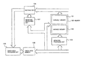
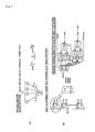
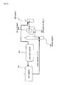
- FIG. 1 A diagram illustrating an embodiment of a decoder according to an LDPC coding scheme of the present invention.
- FIG. 1A A diagram illustrating a specific circuit configuration of the decoder illustrated in FIG. 1 .
- FIG. 2 A diagram showing an example of a Tanner graph (socket model) classified into categories according to the LDPC coding scheme of the present invention.
- FIG. 3 A diagram showing an example of a test matrix which is classified into categories according to the LDPC coding scheme of the present invention.
- FIG. 4 A diagram showing an example of a weighting distribution of variable nodes and check nodes classified into categories according to the LDPC coding scheme of the present invention.
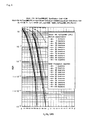
- FIG. 5 A diagram showing a bit error rate characteristic by a Monte Carlo simulation, showing an effect of a scheme for weighting every category according to the LDPC coding scheme of the present invention.
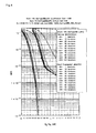
- FIG. 6 A diagram showing a bit error rate characteristic by a Monte Carlo simulation using a conventional single weighting scheme.
- FIG. 7 A diagram illustrating a circuit which is approximated by Hyperbolic tangent rule in check node processing and a Min (Max) Log region which is simplified therefrom.
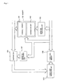
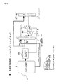
- FIG. 8 A diagram illustrating a first circuit of an encoder architecture according to the LDPC coding scheme of the present invention.
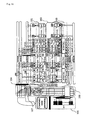
- FIG. 9 A diagram illustrating a second circuit of the encoder architecture according to the LDPC coding scheme of the present invention.
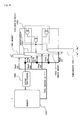
- FIG. 10 A diagram illustrating a circuit which speeds up the second circuit of the encoder architecture according to the LDPC coding scheme of the present invention.
- mean value m u,j for symbol u j with row weight j is:
- Equation 26 Equation 26
- Equation (9) is a recursive equation under a previously given order profile. Development to infinity over time results in error free operation, whereas the development that is stopped in the middle cannot result in the realization of an error free operation.
- the boundary therebetween is called a repetition threshold (Threshold), and Eb/No corresponding to an averaged received LLR value: m u 0 [Equation 28] is a level required to realize error free operation.
- a parameter for tracing the developing process of the aforementioned equation may be only one variable. This can be seen from the following example which is easy to understand. Assuming now taking into consideration an Hyperbolic Tangent Rule in the case of row weight d c ,
- Equation (10) the first term of variance in Equation (10) is:
- Equation (10) the variance in Equation (10) is:
- a balanced state can be held by the statistical natures (variance ⁇ u 2 and mean value m u ) and (variance ⁇ v 2 and mean value m v ) on both sides which can satisfy:
- a balanced state can be held by the statistical natures (variance ⁇ u 2 and mean value m u ) and (variance ⁇ v 2 and mean value m v ) on both sides which can satisfy:
- Equation (21) when the left side of Equation (21) is calculated using a condition which satisfies the relationship of Equation (22);
- Equation (21), Equation (22) is no longer established, thus failing to obtain the merit of simultaneously tracing the variance only with a trace of the mean value alone.
- both the mean value and variance are traced during iterative decoding processing, and a determination is made depending on whether the SNR sufficiently grows.
- the performance is poor if the SNR stops increasing in the middle.
- ⁇ + ( x ) [Equation 91] and ⁇ ⁇ ( x ) [Equation 92] represent a random variable having a magnitude equal to or larger than x: z j [Equation 93] when it is positive and negative.
- Equation ⁇ ⁇ 100 satisfies:
- probability density distribution QL(l) of L to be found is derived by differentiating cumulative probability distribution (cdf) of L of the aforementioned Equation (36) by l:
- a mean value of the MaxLog approximation (also called the “minSum algorithm”) can be calculated by:
- the variance can be calculated by:
- Equation (32) results in GA in a Tanner graph which is classified into categories including non-linear processing resulting from the MaxLog approximation (or also called the “minSum algorithm”). The result of searching for optimal weighting with the GA will be shown in the following example.
- FIG. 2 An implemented socket model is shown in FIG. 2 ; a test matrix in FIG. 3 ; and a correspondence table in FIG. 4 .
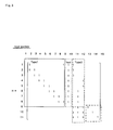
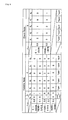
- Multi-Type This example is called “Multi-Type,” where categories are provided for each Type. It is understood from the polynomial of the aforementioned Equation (40), the socket model in FIGS. 2 to 4 , and the like that it is a single row weight having a row weight of four. Optimal weighting is searched by the GA in the Tanner graph in which this example is classified into categories including non-linear processing resulting from the aforementioned MaxLog approximation (or also called the “minSum algorithm”). Locations corresponding to the weighting are indicated in a block diagram as in FIG. 1 . Specifically, this is configured such that each different category is independently weighted. Values which demonstrate the highest performance with the weighting at the corresponding locations on the figure are written in the left of the following table in the following manner:
- weighting is the highest at 0.98 in column weight 2 that has an RA structure and others are approximately in a range of 0.58 to 0.62.
- this is because a node in a category having the RA structure is given highly reliable LLR from other high column weights, whereas a node in a category other than the RA structure is given a low reliable LLR from low column weights from the RA structure, so that the category with the RA structure is heavily weighted, while other categories are lightly weighted.
- FIG. 5 The result of a Monte Carlo simulation performed with an LDPC decoder using the actual MaxLog approximation based on the foregoing result is shown in FIG. 5 .
- the left-hand line represents a characteristic using sum-product
- the right-hand line represents a characteristic using the MaxLog approximation (or also called the “minSum algorithm”). Weighting used under this condition is as follows:
- the weighting at a location with a column weight of two having the RA structure is also highest with 0.9999, and others present values in a range of 0.58 to 0.69, as shown by the above result. It is understood that the same tendency is seen even though the values slightly shift due to different operating points of several objects to be optimized.
- FIG. 6 shows the result of optimizing weighting coefficients by a method of performing single weighting on all conventional nodes having completely the same contents in other aspects, and performing a Monte Carlo simulation.
- a table in which weighting coefficients are used in that event is shown below.
- the right-hand line using the MaxLog approximation (or also called the “minSum algorithm”) cannot be used with a single weighting coefficient alone because an error floor occurs.
- FIG. 1 is a block diagram illustrating the configuration of a decoder which performs weighting on a category-by-category basis using the MaxLog approximation (or also called the “minSum algorithm”) by a Tanner graph classified into categories of the present invention
- FIG. 1A is a diagram illustrating a specific circuit configuration of the same.
- the decoder illustrated in FIG. 1 comprises memory 100 including variable node memories 101 and 102 ; weighting processing units 103 , 107 ; subtractor 104 ; check node processing unit 105 ; and check node memory 106 .
- Variable node memories 101 and 102 for storing variable nodes are switched to the output and input, respectively, when in use, and their interiors are divided by memory banks (not shown) in accordance with a category division in the Tanner graph. Also, an area is provided for storing received value LLR, and an output section responsible for output of variable node adds the received value LLR to a variable node and outputs the result when it outputs the variable node.
- variable node memories 101 and 102 are currently used for the output and input, respectively.
- variable node LLR output in the foregoing manner is weighted by weighting processing unit 103 corresponding to a category by making a selection and polarization represented by:
- Check node processing unit 105 detects the first minimum, second minimum, the polarity signal which is caused by modulo-2 addition, and the positions of the minima for the MaxLog approximation (or also called the “minSum”).
- FIG. 7 A specific circuit configuration of check node processing unit 105 is illustrated in FIG. 7 .
- the Hyperbolic tangent rule is realized by an approximation algorithm in a Min(Max) Log region.
- a message update norm in check node processing is called “Hyperbolic tangent rule,” and is pipelined in a parallel configuration, as illustrated in FIG. 7( b ), so that the operation is completed in one clock on average.
- the circuit operation performs a minimum value detection (min) in a tree configuration, and performs a second minimum value detection (Sub-min) with the minimum value being masked. Through operations at two steps, all processing is completed equivalently in one clock because they are pipelined. It should be noted that F/Fs for pipeline are omitted in the figure because they would otherwise cause complexity.
- check node processing unit 105 After this check node processing is performed by check node processing unit 105 , resulting values (min, Sub-min, sign which is a polarity signal which is caused by modulo-2 addition, and Position indicative of the position of the minimum value) are stored in check node memory 106 .
- Check node memory 106 comprises two memory units which are used as an input or an output like memory 100 , and stores the values resulting from the processing of check node processing unit 105 in the input memory unit. Also, simultaneously, LLR which is the value of u in Equation (41) derived by selection and polarization that uses them is stored in variable node memory 102 . In this event, weighting previously determined on a category-by-category basis is performed in weighting processing unit 103 before being stored in 102 .
- the weighting processing may be performed before the received value LLR is added in variable node memory 101 which is the output, or the weighting processing may be performed in check node processing unit 105 when outputting.
- variable node memory 102 is the output, while variable node memory 101 is the input at this time.
- weighting processing unit 103 is also adapted to act on variable node memory 101 which is the input.
- check node memory 106 in a two-part configuration also switches between the input and output, and processing for repeatedly switching the input and output of memory alternately from one cycle to another is performed until a previously determined number of times of repetitions is reached.
- Access to these memories is further divided according to memory banks within the memory banks divided on a category-by-category basis in accordance with a weight distribution in the categories, such that the processing progresses in parallel. Also, since memory access operations are performed through a caching circuit having a FIFO function taking into consideration of a scenario where parallel accesses temporarily concentrate one a timing due to the relationship of the weight distribution in each category, an increase in the number of divided memory banks, and a reduction in the number of on-chip buses are performed by an averaging effect.
- connection information determined by a Tanner graph has a memory which preserves the positions of 1's in the test matrix in the form of an index, and LLR connection control is conducted using a small memory capacity.
- the relationship between the category and column weights substantially corresponds in this example.
- the weighting can be freely determined through categorization irrespective of the column weights, grouping based on the column weights can also be included in the category like this example.
- Test matrix H determined by a low-order profile involves a small amount of processing for decoding and is suitable for lower complexity because it is a sparse matrix.
- generation matrix G corresponding to sparse test matrix H is not a sparse matrix
- encoding processing is not negligible with respect to decoding processing.
- the encoding processing operation of the present invention comprises an offline process (Offline process) for previously performing a calculation (Pre-calculation), and a hardware-based online process (Online process).
- offline process for previously performing a calculation
- Online process a hardware-based online process
- the previously performed offline process performs a matrix transformation while maintaining the sparse nature of the test matrix.
- the hardware-based online process executes the encoding processing operation at high speeds based on four matrixes A, B, T and F which are created while maintaining the sparse nature of the test matrix.
- Equation ⁇ ⁇ 117 ] H [ A B T C D E ] ( 42 ) where T is a lower triangular matrix having “1” at diagonal elements, and is multiplied by:
- s represents an information bit series
- p 1 , p 2 represent parity bit series, respectively.
- Parity bit series p 1 which is part of the encoder output, is generated from given information bit series s based on the aforementioned equation at high speeds.
- first memory 801 accumulates the position of element 1 of matrix F produced by the offline process as an index, and information bit series S is stored in second memory 802 which is addressed by first row counter 803 and is further addressed by the index output by this first memory 801 .
- third memory 901 stores the sum of a product of parity series p 1 resulting from the online process by Equation (47) and matrix B resulting from the aforementioned offline process and a product of the aforementioned information bit series S and matrix A resulting from the offline process: ( ⁇ A ⁇ s T ⁇ B ⁇ p 1 T [Equation 129] and fourth memory 902 accumulates positions of elements “1” in matrix T resulting from the offline process as indexes.
- Fifth memory 903 is a memory which stores second parity series p 2 , and uses an index output by fourth memory 902 addressed by second row counter 904 as a read address, and selector 907 is controlled by second row counter 904 such that the output of fifth memory 903 and the output of third memory 901 which stores: ( ⁇ A ⁇ s T ⁇ B ⁇ p 1 T [Equation 130] take an exclusive OR only at the first time, and subsequently, selector 907 switches to second parity series p 2 , thereby causing exclusive OR circuit 905 and delay element 906 to execute the processing of Equation (50).
- the hardware-based processing of: ( ⁇ A ⁇ s T ⁇ B ⁇ p 1 T ) [Equation 131] is a normal design matter, so that a description thereon is omitted here.
- the encoder of the present invention is configured by the foregoing offline process and the hardware-based online process illustrated in FIGS. 8 and 9 .
- FIG. 10 is a higher speed version of the circuit of FIG. 9 which is responsible for most of loads of the encoding processing, and operates, in a manner similar to that illustrated in FIG. 9 , using the positions of elements 1 of matrix T in memory 1002 addressed by second row counter 1004 as indexes.
- FIG. 10 differs from the configuration illustrated in FIG. 9 only in that there are a number of indexes equal to the number of row weights, and that the indexes for the positions of all 1's within the same row are addressed in parallel to memory 1003 which stores second parity series p 2 .
- mirror memories 1003 - 1 , 2 are added as memories for storing second parity series p 2 , and the processing of Equation (50) is performed at a time together with the output of third memory 1001 which stores: ( ⁇ A ⁇ s T ⁇ B ⁇ p 1 T ) [Equation 132] by exclusive OR circuit 1005 , and the result is stored in memory 1003 including mirror memories 1003 - 1 , 2 , which stores second parity series p 2 to accomplish fast operations.
Abstract
Description
- Non-Patent Document 1: “Efficient encoding of low-density parity-check codes,” IEEE Transactions on information theory, Volume 47,
Issue 2, pp. 638-656 - Patent Document 1: JP-2005-65271A
- Patent Document 2: Japanese Patent No. 3246484
- Patent Document 3: JP-2004-266463A
including a lower triangular matrix T having 1's at diagonal elements by a matrix manipulation of a test matrix H, further having
F=(−E·T −1 ·B+D)−1·(E·T −1 ·A−C) [Equation 2]
from the upper triangular zero matrix, wherein the
−A·s T −B·p 1 T [Equation 3]
by taking a product of parity series p1 and matrix B resulting from the offline process, taking a product of information bit series S and the matrix A resulting from the offline process, and taking an exclusive OR of the products, having
including a lower triangular matrix T having 1's at diagonal elements by a matrix manipulation of test matrix H by a previously calculated offline process;
F=(−E·T −1 ·B+D)−1·(E·T −1 ·A−C) [Equation 5]
from the upper triangular zero matrix by a previously calculated offline process;
−A·s T −B·p 1 T [Equation 6]
by taking a product of first parity series p1 and matrix B produced by the offline process, taking a product of information bit series S and matrix A produced by the offline process, and taking an exclusive OR of the products;
including lower triangular matrix T having 1's at diagonal elements by a matrix manipulation of test matrix H, further having
F=(−E·T −1 ·B+D)−1·(E·T −1 ·A−C) [Equation 8]
from the upper triangular zero matrix, wherein means 1 and 2 are previously calculated offline processes, and have
−A·s T −B·p 1 T [Equation 9]
by taking a product of parity series p1 and matrix B resulting from the offline process, taking a product of information bit series S and matrix A resulting from the offline process, and taking an exclusive OR of the products, having
- 101 Memory for Storing Variable Node LLR
- 102 Memory for Storing Variable Node LLR
- 103 Weighting Processing Unit
- 104 Subtractor
- 105 Check Node Processing Unit
- 106 Check Node Memory
- 107 Weighting Processing Unit
- 801 First Memory
- 802 Second Memory
- 803 First Row Counter
- 804 Exclusive OR
- 805 Delay Element
- 806 Memory for Parity Series p1
- 901 Third Memory
- 902 Fourth Memory
- 903 Fifth Memory
- 904 Row Counter
- 905 Exclusive OR
- 906 Delay Element
- 1001 Third Memory
- 1002 Fourth Memory
- 1003 Fifth Memory
- 1003-1, 2 Mirror Memories
- 1004 Second Row Counter
- 1005 Exclusive OR
[Equation 10]
m vi =E[v i ]=m u
the following relationship is derived.
[Equation 13]
σ2=2·μ
[Equation 15]
where; Gaussian;
is derived. Accordingly, the following relationship is derived.
assuming an in ensemble average,
and
in Equation (5), the following equation is derived:
m v,j =E[v i ]=m u
in Equation (1), the following recursive equation for singularity is derived:
m u
is a level required to realize error free operation.
so that an expected value must be considered the statistical nature (variance σu 2 and mean value mu) for random variable u on the left side, and the statistical nature (variance σv 2 and mean value mv) for a random variable on the right side:
νk k=1,2, . . . ,d
νk k−1,2, . . . ,d
are independent of one another and have the same statistical nature,
where:
in the above equation is omitted because it does not include an integral variable but is a fixed value, and a remaining non-integral function is expressed by:
ƒ(x) [Equation 38]
ƒ(x) [Equation 41]
is an odd function. Therefore,
is established. In GA which satisfies arbitrary
from
a balanced state can be held by the statistical natures (variance σu 2 and mean value mu) and (variance σv 2 and mean value mv) on both sides which can satisfy:
from which it is understood that the relationship of Equation (21) and Equation (22), i.e., the relationship between the mean value and variance, is established without contradiction. In other words, the trace of the mean value and its variance in Hyperbolic Tangent Rule simultaneously trace the variance as well even with a trace of the mean value alone, one variable may only be observed.
d=(d 1 ,d 2 , . . . ,d u
which is collected for each
νbd(i.e. 0.5,0.3,0.2,0.2) [Equation 56]
m(i)ν,d [Equation 58]
is:
is used for noting the proportion of branches connected to nodes of the order arbitrarily selected within branches of category i:
d=(d 1 ,d 2 , . . . ,d n
the proportion of branches connected to the nodes of the arbitrarily selected order:
is, after all,
d=(d 1 ,d 2 , . . . ,d u
which is collected for each
νbd(i.e. 0.5,0.3,0.2,0.2) [Equation 68]
m(i)u,d [Equation 70]
is:
using “tan h rule” in sumProduct. Here, the following relationship:
is used for noting the proportion of branches connected to nodes of the order arbitrarily selected within branches of category i:
d=(d 1 ,d 2 , . . . ,d u
the proportion of branches connected to the nodes of the arbitrarily selected order:
d=(d 1 ,d 2 , . . . ,d u
is:
is similarly established for j as well, the following equation is derived:
the following recursive equation is derived for GA in the Tanner graph classified into categories:
an average behavior can be seen in a iterative decoding process by recursive equation (32). Error-free operation can be realized when mean value m evolves to infinity from one repetition to another, whereas error-free operation cannot be realized when the evolution stops in the middle. Its boundary is called a repetition threshold (Threshold), and Eb/N0 corresponding to communication path LLR average m(i)u0 i=1−ne at that time is a level required to realize error-free operation. Also, in the aforementioned equation,
is established.
Z=[z 1 ,z 2 , . . . ,z d
in vector notation, and respective probability density function is represented as:
P z
where mj is a mean value, and σ2j is a variance. Further, the probability function is defined as follows. For
φ+(x) [Equation 91]
and
φ−(x) [Equation 92]
represent a random variable having a magnitude equal to or larger than x:
z j [Equation 93]
when it is positive and negative.
Pr(L<l)=Pr{odd number of negative value in Z, and |z j |>|l|,∀j} [Equation 95]
is established for:
l<0 [Equation 94]
|z j| [Equation 96]
is equal to or larger than:
|t| [Equation 97]
min{|z j|} [Equation 98]
is also equal to or larger than:
|l| [Equation 99]
min{|z j|} [Equation 101]
in a negative region (odd number of negative value in Z) approximated by:
satisfies:
|z j |>|l| [Equation 102]
so that:
L<l<0 [Equation 103]
is established, so that all events; in the region are defined by the following equation:
{Odd number of negative value in Z, and |z i |>|l|,∀j} [Equation 104]
are included in:
Pr(L<l) [Equation 105]
|z j| [Equation 106]
are not equal to or larger than:
|l| [Equation 107]
events equal to or smaller than:
|l| [Equation 108]
exist without fail, so that they are not included in:
Pr(L<l) [Equation 109]
| TABLE 1 |
| Variable Node |
| Weighting | b | d |
| Coefficient | υb,d | b0 | b1 | d1 | d2 | d3 | d4 | d5 |
| 0.98 | 0.8 | 0 | 1 | 2 | 0 | 0 | 0 | 0 |
| 0.58~0.62 | 0.1 | 0 | 1 | 0 | 8 | 0 | 0 | 0 |
| 0.58~0.62 | 0.2 | 1 | 0 | 0 | 0 | 3 | 3 | 0 |
| 0.1 | 1 | 0 | 0 | 0 | 2 | 3 | 0 | |
| Don't care | 0.3 | 0 | 1 | 0 | 0 | 0 | 0 | 1 |
| erasure | σ2 | Type1 | Type2 | Type3 | Type4 | Type5 | ||
Weighting Coefficient
| TABLE 2 |
| Variable Node |
| Weighting | b | d |
| Coefficient | υb,d | b0 | b1 | d1 | d2 | d3 | d4 | d5 |
| 0.9999 | 0.8 | 0 | 1 | 2 | 0 | 0 | 0 | 0 |
| 0.58 | 0.1 | 0 | 1 | 0 | 8 | 0 | 0 | 0 |
| 0.69 | 0.2 | 1 | 0 | 0 | 0 | 3 | 3 | 0 |
| 0.1 | 1 | 0 | 0 | 0 | 2 | 3 | 0 | |
| Don't care | 0.3 | 0 | 1 | 0 | 0 | 0 | 0 | 1 |
| erasure | σ2 | Type1 | Type2 | Type3 | Type4 | Type5 | ||
Weighting Coefficient
| TABLE 3 |
| Variable Node |
| Weighting | b | d |
| Coefficient | υb,d | b0 | b1 | d1 | d2 | d3 | d4 | d5 |
| 0.81 | 0.8 | 0 | 1 | 2 | 0 | 0 | 0 | 0 |
| 0.81 | 0.1 | 0 | 1 | 0 | 8 | 0 | 0 | 0 |
| 0.81 | 0.2 | 1 | 0 | 0 | 0 | 3 | 3 | 0 |
| 0.1 | 1 | 0 | 0 | 0 | 2 | 3 | 0 | |
| 0.81 | 0.3 | 0 | 1 | 0 | 0 | 0 | 0 | 1 |
| erasure | σ2 | Type1 | Type2 | Type3 | Type4 | Type5 | ||
Weighting Coefficient
for values generated from
ν1˜νn [Equation 115]
in the same row, but is output to check
where T is a lower triangular matrix having “1” at diagonal elements, and is multiplied by:
from the left results in the following matrix:
x=[sp 1 p 2] [Equation 120]
H·X=0 [Equation 121]
between code word vector X and test matrix H,
(2) Hardware Encoding (Online Process)
p 1 T =F·s T [Equation 125]
in Equation (47).
[Equation 126]
T·p 2 T=(−A·s T −B·p 1 T) (48)
where matrix T is a lower triangular matrix having “1” at diagonal elements in the following manner. Therefore,
(−A·s T −B·p 1 T [Equation 129]
and
(−A·s T −B·p 1 T [Equation 130]
take an exclusive OR only at the first time, and subsequently,
(−A·s T −B·p 1 T) [Equation 131]
is a normal design matter, so that a description thereon is omitted here.
(−A·s T −B·p 1 T) [Equation 132]
by exclusive OR circuit 1005, and the result is stored in
Claims (21)
F=(−E·T −1 ·B+D)−1·(E·T −1 ·A−C) [Equation 2]
−A·s T −B·p 1 T [Equation 3]
Applications Claiming Priority (3)
| Application Number | Priority Date | Filing Date | Title |
|---|---|---|---|
| JP2005141588 | 2005-05-13 | ||
| JP2005-141588 | 2005-05-13 | ||
| PCT/JP2006/308116 WO2006120844A1 (en) | 2005-05-13 | 2006-04-18 | Encoder and decoder by ldpc encoding |
Publications (1)
| Publication Number | Publication Date |
|---|---|
| US8140930B1 true US8140930B1 (en) | 2012-03-20 |
Family
ID=37396357
Family Applications (1)
| Application Number | Title | Priority Date | Filing Date |
|---|---|---|---|
| US11/914,328 Expired - Fee Related US8140930B1 (en) | 2005-05-13 | 2006-04-18 | Encoder and decoder by LDPC coding |
Country Status (6)
| Country | Link |
|---|---|
| US (1) | US8140930B1 (en) |
| EP (1) | EP1881610B1 (en) |
| JP (1) | JP5315693B2 (en) |
| KR (4) | KR20090106620A (en) |
| CN (1) | CN101233693B (en) |
| WO (1) | WO2006120844A1 (en) |
Cited By (41)
| Publication number | Priority date | Publication date | Assignee | Title |
|---|---|---|---|---|
| US20080276156A1 (en) * | 2007-05-01 | 2008-11-06 | Texas A&M University System | Low density parity check decoder for regular ldpc codes |
| US20100125769A1 (en) * | 2008-11-14 | 2010-05-20 | Realtek Semiconductor Corp. | Parity-check-code decoder and recording controller |
| US20120297267A1 (en) * | 2010-01-27 | 2012-11-22 | Telefonaktiebolaget L M Ericsson (Publ) | Error floor reduction in iteratively decoded fec codes |
| US8473824B1 (en) * | 2008-09-08 | 2013-06-25 | Marvell International Ltd. | Quasi-cyclic low-density parity-check (QC-LDPC) encoder |
| WO2013147777A1 (en) * | 2012-03-28 | 2013-10-03 | Intel Corporation | Updating variable nodes associated with an iterative decoder |
| US8661326B1 (en) * | 2010-08-04 | 2014-02-25 | Marvell International Ltd. | Non-binary LDPC code decoding early termination |
| US8713398B2 (en) * | 2011-03-22 | 2014-04-29 | Nec Corporation | Error correct coding device, error correct coding method, and error correct coding program |
| US8756476B2 (en) | 2010-11-10 | 2014-06-17 | Huawei Technologies Co., Ltd. | Method and apparatus for decoding low-density parity-check codes |
| US20140201588A1 (en) * | 2013-01-16 | 2014-07-17 | Broadcom Corporation | Low density parity check (LDPC) coding in communication systems |
| US20140201592A1 (en) * | 2013-01-16 | 2014-07-17 | Broadcom Corporation | Very short size LDPC coding for physical and/or control channel signaling |
| US8930790B1 (en) * | 2013-09-13 | 2015-01-06 | U-Blox Ag | Method and apparatus for identifying selected values from among a set of values |
| US8935598B1 (en) * | 2013-03-12 | 2015-01-13 | Pmc-Sierra Us, Inc. | System and method for adaptive check node approximation in LDPC decoding |
| US8984376B1 (en) | 2013-03-14 | 2015-03-17 | Pmc-Sierra Us, Inc. | System and method for avoiding error mechanisms in layered iterative decoding |
| US8984365B1 (en) | 2013-03-14 | 2015-03-17 | Pmc-Sierra Us, Inc. | System and method for reduced memory storage in LDPC decoding |
| US8990661B1 (en) | 2013-03-05 | 2015-03-24 | Pmc-Sierra Us, Inc. | Layer specific attenuation factor LDPC decoder |
| US8995302B1 (en) | 2013-01-16 | 2015-03-31 | Pmc-Sierra Us, Inc. | Method and apparatus for translated routing in an interconnect switch |
| US9092353B1 (en) | 2013-01-29 | 2015-07-28 | Pmc-Sierra Us, Inc. | Apparatus and method based on LDPC codes for adjusting a correctable raw bit error rate limit in a memory system |
| US9128858B1 (en) | 2013-01-29 | 2015-09-08 | Pmc-Sierra Us, Inc. | Apparatus and method for adjusting a correctable raw bit error rate limit in a memory system using strong log-likelihood (LLR) values |
| US9235467B2 (en) | 2013-03-15 | 2016-01-12 | Pmc-Sierra Us, Inc. | System and method with reference voltage partitioning for low density parity check decoding |
| US9397701B1 (en) | 2013-03-11 | 2016-07-19 | Microsemi Storage Solutions (Us), Inc. | System and method for lifetime specific LDPC decoding |
| US20160233885A1 (en) * | 2015-02-11 | 2016-08-11 | Commissariat A L'energie Atomique Et Aux Energies Alternatives | Iterative decoding method of lfsr sequences with a low false-alarm probability |
| US9417804B2 (en) | 2014-07-07 | 2016-08-16 | Microsemi Storage Solutions (Us), Inc. | System and method for memory block pool wear leveling |
| US9450610B1 (en) | 2013-03-15 | 2016-09-20 | Microsemi Storage Solutions (Us), Inc. | High quality log likelihood ratios determined using two-index look-up table |
| US9454414B2 (en) | 2013-03-15 | 2016-09-27 | Microsemi Storage Solutions (Us), Inc. | System and method for accumulating soft information in LDPC decoding |
| US9590657B2 (en) * | 2015-02-06 | 2017-03-07 | Alcatel-Lucent Usa Inc. | Low power low-density parity-check decoding |
| US9590656B2 (en) | 2013-03-15 | 2017-03-07 | Microsemi Storage Solutions (Us), Inc. | System and method for higher quality log likelihood ratios in LDPC decoding |
| US9799405B1 (en) | 2015-07-29 | 2017-10-24 | Ip Gem Group, Llc | Nonvolatile memory system with read circuit for performing reads using threshold voltage shift read instruction |
| US9813080B1 (en) | 2013-03-05 | 2017-11-07 | Microsemi Solutions (U.S.), Inc. | Layer specific LDPC decoder |
| US9886214B2 (en) | 2015-12-11 | 2018-02-06 | Ip Gem Group, Llc | Nonvolatile memory system with erase suspend circuit and method for erase suspend management |
| US9892794B2 (en) | 2016-01-04 | 2018-02-13 | Ip Gem Group, Llc | Method and apparatus with program suspend using test mode |
| US9899092B2 (en) | 2016-01-27 | 2018-02-20 | Ip Gem Group, Llc | Nonvolatile memory system with program step manager and method for program step management |
| US9935654B2 (en) | 2015-02-06 | 2018-04-03 | Alcatel-Lucent Usa Inc. | Low power low-density parity-check decoding |
| US10157677B2 (en) | 2016-07-28 | 2018-12-18 | Ip Gem Group, Llc | Background reference positioning and local reference positioning using threshold voltage shift read |
| US10230396B1 (en) | 2013-03-05 | 2019-03-12 | Microsemi Solutions (Us), Inc. | Method and apparatus for layer-specific LDPC decoding |
| US10236915B2 (en) | 2016-07-29 | 2019-03-19 | Microsemi Solutions (U.S.), Inc. | Variable T BCH encoding |
| US10291263B2 (en) | 2016-07-28 | 2019-05-14 | Ip Gem Group, Llc | Auto-learning log likelihood ratio |
| US20190188087A1 (en) * | 2016-07-15 | 2019-06-20 | Quantum Corporation | Joint de-duplication-erasure coded distributed storage |
| US10332613B1 (en) | 2015-05-18 | 2019-06-25 | Microsemi Solutions (Us), Inc. | Nonvolatile memory system with retention monitor |
| US10742355B2 (en) | 2019-01-03 | 2020-08-11 | Samsung Electronics Co., Ltd. | Apparatus that receives non-binary polar code and decoding method thereof |
| CN112005499A (en) * | 2018-10-18 | 2020-11-27 | 华为技术有限公司 | Decoding method and device of LDPC code |
| US11200484B2 (en) * | 2018-09-06 | 2021-12-14 | International Business Machines Corporation | Probability propagation over factor graphs |
Families Citing this family (14)
| Publication number | Priority date | Publication date | Assignee | Title |
|---|---|---|---|---|
| JP4526451B2 (en) | 2005-06-30 | 2010-08-18 | ルネサスエレクトロニクス株式会社 | Decoding apparatus, method, and program |
| JP4526450B2 (en) * | 2005-06-30 | 2010-08-18 | ルネサスエレクトロニクス株式会社 | Decoding apparatus, method, and program |
| JP4645640B2 (en) * | 2007-11-30 | 2011-03-09 | 住友電気工業株式会社 | Decoder, receiving device, and decoding method of encoded data |
| CN101299612B (en) * | 2008-06-10 | 2013-04-24 | 上海瀚讯无线技术有限公司 | Method for rapidly sorting tree graph |
| JP5197544B2 (en) * | 2009-10-05 | 2013-05-15 | 株式会社東芝 | Memory system |
| JP5091996B2 (en) * | 2010-09-09 | 2012-12-05 | 株式会社東芝 | Error correction decoder, memory controller and receiver |
| JP5132758B2 (en) * | 2010-12-13 | 2013-01-30 | 株式会社東芝 | Error correction decoder and storage device |
| JP5648852B2 (en) * | 2011-05-27 | 2015-01-07 | ソニー株式会社 | Data processing apparatus and data processing method |
| JP5664919B2 (en) * | 2011-06-15 | 2015-02-04 | ソニー株式会社 | Data processing apparatus and data processing method |
| US9191256B2 (en) | 2012-12-03 | 2015-11-17 | Digital PowerRadio, LLC | Systems and methods for advanced iterative decoding and channel estimation of concatenated coding systems |
| JP5971670B2 (en) | 2013-12-09 | 2016-08-17 | 三菱電機株式会社 | Error correction decoding device |
| CN108574493B (en) * | 2017-03-10 | 2021-12-24 | 华为技术有限公司 | Data processing method and device |
| TWI657669B (en) * | 2017-11-28 | 2019-04-21 | 財團法人資訊工業策進會 | Low density parity check code decoder and decoding method thereof |
| CN111208538B (en) * | 2018-11-21 | 2022-04-26 | 展讯通信(上海)有限公司 | Method and device for demodulating text |
Citations (15)
| Publication number | Priority date | Publication date | Assignee | Title |
|---|---|---|---|---|
| JP2003198383A (en) | 2001-12-27 | 2003-07-11 | Mitsubishi Electric Corp | Inspection matrix generation method for ldpc coding |
| JP2003244109A (en) | 2002-02-13 | 2003-08-29 | Mitsubishi Electric Corp | Communication system, receiver, transmitter and communication method |
| US20030229843A1 (en) | 2002-06-11 | 2003-12-11 | Nam-Yul Yu | Forward error correction apparatus and method in a high-speed data transmission system |
| WO2004049578A1 (en) | 2002-11-27 | 2004-06-10 | Koninklijke Philips Electronics N.V. | Running minimum message passing ldpc decoding |
| JP2004186940A (en) | 2002-12-03 | 2004-07-02 | Nec Corp | Error correction code decoding device |
| JP2004266463A (en) | 2003-02-28 | 2004-09-24 | Mitsubishi Electric Corp | Inspection matrix generation method and inspection matrix generation device |
| EP1482643A2 (en) | 2003-05-26 | 2004-12-01 | Samsung Electronics Co., Ltd. | Method and apparatus for decoding a low density parity check (LDPC) code in a communication system |
| JP2005065271A (en) | 2003-08-08 | 2005-03-10 | Lucent Technol Inc | Decoding method and apparatus |
| US6938196B2 (en) * | 2001-06-15 | 2005-08-30 | Flarion Technologies, Inc. | Node processors for use in parity check decoders |
| KR20060057253A (en) | 2004-11-23 | 2006-05-26 | 삼성전자주식회사 | Decoding method and apparatus of low density parity code using unified processing |
| US7103819B2 (en) * | 2002-08-27 | 2006-09-05 | Sony Corporation | Decoding device and decoding method |
| US7174495B2 (en) * | 2003-12-19 | 2007-02-06 | Emmanuel Boutillon | LDPC decoder, corresponding method, system and computer program |
| US7197690B2 (en) * | 2002-05-31 | 2007-03-27 | Broadcom Corporation | Bandwidth efficient coded modulation scheme based on MLC (multi-level code) signals having multiple maps |
| US7237181B2 (en) * | 2003-12-22 | 2007-06-26 | Qualcomm Incorporated | Methods and apparatus for reducing error floors in message passing decoders |
| EP1884023A1 (en) | 2005-05-20 | 2008-02-06 | Mitsubishi Electric Corporation | Normalized belief propagation decoding |
Family Cites Families (1)
| Publication number | Priority date | Publication date | Assignee | Title |
|---|---|---|---|---|
| KR20060032464A (en) * | 2004-10-12 | 2006-04-17 | 삼성전자주식회사 | Efficient decoding method and apparatus of low density parity code |
-
2006
- 2006-04-18 EP EP06732045.7A patent/EP1881610B1/en not_active Expired - Fee Related
- 2006-04-18 JP JP2007528155A patent/JP5315693B2/en not_active Expired - Fee Related
- 2006-04-18 KR KR1020097017454A patent/KR20090106620A/en not_active IP Right Cessation
- 2006-04-18 CN CN2006800165262A patent/CN101233693B/en not_active Expired - Fee Related
- 2006-04-18 US US11/914,328 patent/US8140930B1/en not_active Expired - Fee Related
- 2006-04-18 KR KR1020137004821A patent/KR101356808B1/en active IP Right Grant
- 2006-04-18 KR KR1020077026683A patent/KR100945991B1/en active IP Right Grant
- 2006-04-18 KR KR1020117023498A patent/KR101390544B1/en active IP Right Grant
- 2006-04-18 WO PCT/JP2006/308116 patent/WO2006120844A1/en active Application Filing
Patent Citations (15)
| Publication number | Priority date | Publication date | Assignee | Title |
|---|---|---|---|---|
| US6938196B2 (en) * | 2001-06-15 | 2005-08-30 | Flarion Technologies, Inc. | Node processors for use in parity check decoders |
| JP2003198383A (en) | 2001-12-27 | 2003-07-11 | Mitsubishi Electric Corp | Inspection matrix generation method for ldpc coding |
| JP2003244109A (en) | 2002-02-13 | 2003-08-29 | Mitsubishi Electric Corp | Communication system, receiver, transmitter and communication method |
| US7197690B2 (en) * | 2002-05-31 | 2007-03-27 | Broadcom Corporation | Bandwidth efficient coded modulation scheme based on MLC (multi-level code) signals having multiple maps |
| US20030229843A1 (en) | 2002-06-11 | 2003-12-11 | Nam-Yul Yu | Forward error correction apparatus and method in a high-speed data transmission system |
| US7103819B2 (en) * | 2002-08-27 | 2006-09-05 | Sony Corporation | Decoding device and decoding method |
| WO2004049578A1 (en) | 2002-11-27 | 2004-06-10 | Koninklijke Philips Electronics N.V. | Running minimum message passing ldpc decoding |
| JP2004186940A (en) | 2002-12-03 | 2004-07-02 | Nec Corp | Error correction code decoding device |
| JP2004266463A (en) | 2003-02-28 | 2004-09-24 | Mitsubishi Electric Corp | Inspection matrix generation method and inspection matrix generation device |
| EP1482643A2 (en) | 2003-05-26 | 2004-12-01 | Samsung Electronics Co., Ltd. | Method and apparatus for decoding a low density parity check (LDPC) code in a communication system |
| JP2005065271A (en) | 2003-08-08 | 2005-03-10 | Lucent Technol Inc | Decoding method and apparatus |
| US7174495B2 (en) * | 2003-12-19 | 2007-02-06 | Emmanuel Boutillon | LDPC decoder, corresponding method, system and computer program |
| US7237181B2 (en) * | 2003-12-22 | 2007-06-26 | Qualcomm Incorporated | Methods and apparatus for reducing error floors in message passing decoders |
| KR20060057253A (en) | 2004-11-23 | 2006-05-26 | 삼성전자주식회사 | Decoding method and apparatus of low density parity code using unified processing |
| EP1884023A1 (en) | 2005-05-20 | 2008-02-06 | Mitsubishi Electric Corporation | Normalized belief propagation decoding |
Non-Patent Citations (17)
| Title |
|---|
| Farhad Zarkeshvari & Amir H. Banihashemi, On Implementation of Min-Sum Algorithm for Decoding Low-Density Parity-Check (LDPC) Codes, Global Telecommunications Conference, 2002. GLOBECOM '02, vol. 2, Nov. 2002, pp. 1349 to 1353. |
| J. Chen et al., "Density Evolution for Two Improved BP-Based Decoding Algorithms of LDPC Codes", IEEE Communications Letters, vol. 6, No. 5, May 2002, pp. 208-210. |
| J. Chen et al., "Improved Min-Sum Decoding Algorithms for Irregular LDPC Codes", IEEE International Symposium on Information Theory, XP010846293, Sep. 4, 2005. |
| J. Heo, "Analysis of scaling soft information on low density parity check code", Electronics Letters, vol. 39, No. 2, Jan. 23, 2003. |
| J. Heo, "Performance and Convergence Analysis of Improved Min-Sum Iterative Decoding Algorithm", IEICE Trans. Commun., vol. E87-B, No. 10, Oct. 1, 2004, pp, 2847-2858. |
| J. Zhang et al., "Improved Min-Sum Decoding of LDPC Codes Using 2-Dimensional Normalization", IEEE Global Telecommunications Conference, Globecom '05, vol. 3, Nov. 28, 2005, pp. 1187-1192. |
| Korean Office Action issued Feb. 23, 2009 for KR Application No. 10-2007-7026683. |
| Ohhashi et al., "Performance Analysis of BP-based Algorithms for Irregular Low-Density Parity-Check Codes On Fast Rayleigh Fading Channel", IEEE 60th Vehicular Technology Conference, vol. 4, Sep. 26, 2004, pp. 2530-2534. |
| PCT/JP2006/308116 International Search Report mailed Jun. 20, 2006. |
| Sae-Young Chung, Thomas J. Richardson, and Rudiger L. Urbanke, Analysis of Sum-Product Decoding of Low-Density Parity-Check Codes Using a Gaussian Approximation, IEEE Transactions on Information Theory, vol. 47, No. 2, Feb. 2001, pp. 657 to 670. |
| Supplementary European Search Report for EP 06 73 2045 dated Sep. 6, 2010. |
| Thomas J. Richardson & Rudiger J. Urbanke, Efficient Encoding of Low-Density Parity-Check Codes, IEEE Transactions on Information Theory, vol. 47, No. 2, Feb. 2001, pp. 638 to 656. |
| Tom Richardson & Rudiger Urbanke, Multi-Edge Type LDPC Codes, Apr. 20, 2004 pp. 1 to 36, http://ece.iisc.ernet.in/~vijay/multiedge.pdf. |
| Tom Richardson & Rudiger Urbanke, Multi-Edge Type LDPC Codes, Apr. 20, 2004 pp. 1 to 36, http://ece.iisc.ernet.in/˜vijay/multiedge.pdf. |
| Tom Richardson, Multi-edge type LDPC codes, On the occasion of Bob McEliece's 60th birthday celebration, Feb. 3, 2003, http://www.systems.caltech.edu/~jeremy/research/other-papers) pp. 1 to 52 http://www.systems/caltech.edu/~jeremy/research/other-papers/McEliece-bday.pdf-1.pdf. |
| Tom Richardson, Multi-edge type LDPC codes, On the occasion of Bob McEliece's 60th birthday celebration, Feb. 3, 2003, http://www.systems.caltech.edu/˜jeremy/research/other—papers) pp. 1 to 52 http://www.systems/caltech.edu/˜jeremy/research/other—papers/McEliece—bday.pdf—1.pdf. |
| Yen-Chin Liao et al., "A Dynamic Normalization Technique for Decoding LDPC Codes", IEEE Workshop on Signal Processing System Design and Implementation, SIPS 2005, 2005, pp. 768-772. |
Cited By (65)
| Publication number | Priority date | Publication date | Assignee | Title |
|---|---|---|---|---|
| US11368168B2 (en) | 2007-05-01 | 2022-06-21 | The Texas A&M University System | Low density parity check decoder |
| US20080276156A1 (en) * | 2007-05-01 | 2008-11-06 | Texas A&M University System | Low density parity check decoder for regular ldpc codes |
| US8656250B2 (en) | 2007-05-01 | 2014-02-18 | Texas A&M University System | Low density parity check decoder for regular LDPC codes |
| US10615823B2 (en) | 2007-05-01 | 2020-04-07 | The Texas A&M University System | Low density parity check decoder |
| US8359522B2 (en) | 2007-05-01 | 2013-01-22 | Texas A&M University System | Low density parity check decoder for regular LDPC codes |
| US10951235B2 (en) | 2007-05-01 | 2021-03-16 | The Texas A&M University System | Low density parity check decoder |
| US8418023B2 (en) * | 2007-05-01 | 2013-04-09 | The Texas A&M University System | Low density parity check decoder for irregular LDPC codes |
| US9112530B2 (en) | 2007-05-01 | 2015-08-18 | The Texas A&M University System | Low density parity check decoder |
| US11728828B2 (en) | 2007-05-01 | 2023-08-15 | The Texas A&M University System | Low density parity check decoder |
| US8555140B2 (en) | 2007-05-01 | 2013-10-08 | The Texas A&M University System | Low density parity check decoder for irregular LDPC codes |
| US20080301521A1 (en) * | 2007-05-01 | 2008-12-04 | Texas A&M University System | Low density parity check decoder for irregular ldpc codes |
| US10141950B2 (en) | 2007-05-01 | 2018-11-27 | The Texas A&M University System | Low density parity check decoder |
| US9294130B1 (en) * | 2007-11-30 | 2016-03-22 | Marvell International Ltd. | Quasi-cyclic low-density parity-check (QC-LDPC) encoder |
| US8473824B1 (en) * | 2008-09-08 | 2013-06-25 | Marvell International Ltd. | Quasi-cyclic low-density parity-check (QC-LDPC) encoder |
| US8402340B2 (en) * | 2008-11-14 | 2013-03-19 | Realtek Semiconductor Corp. | Parity-check-code decoder and recording controller |
| US20100125769A1 (en) * | 2008-11-14 | 2010-05-20 | Realtek Semiconductor Corp. | Parity-check-code decoder and recording controller |
| US8732564B2 (en) * | 2010-01-27 | 2014-05-20 | Telefonaktiebolaget L M Ericsson (Publ) | Error floor reduction in iteratively decoded FEC codes |
| US20120297267A1 (en) * | 2010-01-27 | 2012-11-22 | Telefonaktiebolaget L M Ericsson (Publ) | Error floor reduction in iteratively decoded fec codes |
| US9054740B1 (en) | 2010-08-04 | 2015-06-09 | Marvell International Ltd. | Low density parity check decoding with early termination based on nonzero-circulant flags |
| US8661326B1 (en) * | 2010-08-04 | 2014-02-25 | Marvell International Ltd. | Non-binary LDPC code decoding early termination |
| US8756476B2 (en) | 2010-11-10 | 2014-06-17 | Huawei Technologies Co., Ltd. | Method and apparatus for decoding low-density parity-check codes |
| US8713398B2 (en) * | 2011-03-22 | 2014-04-29 | Nec Corporation | Error correct coding device, error correct coding method, and error correct coding program |
| WO2013147777A1 (en) * | 2012-03-28 | 2013-10-03 | Intel Corporation | Updating variable nodes associated with an iterative decoder |
| US9172399B2 (en) | 2012-03-28 | 2015-10-27 | Intel Corporation | Updating variable nodes associated with an iterative decoder |
| US20140201592A1 (en) * | 2013-01-16 | 2014-07-17 | Broadcom Corporation | Very short size LDPC coding for physical and/or control channel signaling |
| US9154261B2 (en) * | 2013-01-16 | 2015-10-06 | Broadcom Corporation | Low density parity check (LDPC) coding in communication systems |
| US8995302B1 (en) | 2013-01-16 | 2015-03-31 | Pmc-Sierra Us, Inc. | Method and apparatus for translated routing in an interconnect switch |
| US9178653B2 (en) * | 2013-01-16 | 2015-11-03 | Broadcom Corporation | Very short size LDPC coding for physical and/or control channel signaling |
| US20140201588A1 (en) * | 2013-01-16 | 2014-07-17 | Broadcom Corporation | Low density parity check (LDPC) coding in communication systems |
| US9092353B1 (en) | 2013-01-29 | 2015-07-28 | Pmc-Sierra Us, Inc. | Apparatus and method based on LDPC codes for adjusting a correctable raw bit error rate limit in a memory system |
| US9128858B1 (en) | 2013-01-29 | 2015-09-08 | Pmc-Sierra Us, Inc. | Apparatus and method for adjusting a correctable raw bit error rate limit in a memory system using strong log-likelihood (LLR) values |
| US9448881B1 (en) | 2013-01-29 | 2016-09-20 | Microsemi Storage Solutions (Us), Inc. | Memory controller and integrated circuit device for correcting errors in data read from memory cells |
| US10230396B1 (en) | 2013-03-05 | 2019-03-12 | Microsemi Solutions (Us), Inc. | Method and apparatus for layer-specific LDPC decoding |
| US8990661B1 (en) | 2013-03-05 | 2015-03-24 | Pmc-Sierra Us, Inc. | Layer specific attenuation factor LDPC decoder |
| US9813080B1 (en) | 2013-03-05 | 2017-11-07 | Microsemi Solutions (U.S.), Inc. | Layer specific LDPC decoder |
| US9397701B1 (en) | 2013-03-11 | 2016-07-19 | Microsemi Storage Solutions (Us), Inc. | System and method for lifetime specific LDPC decoding |
| US8935598B1 (en) * | 2013-03-12 | 2015-01-13 | Pmc-Sierra Us, Inc. | System and method for adaptive check node approximation in LDPC decoding |
| US8984376B1 (en) | 2013-03-14 | 2015-03-17 | Pmc-Sierra Us, Inc. | System and method for avoiding error mechanisms in layered iterative decoding |
| US8984365B1 (en) | 2013-03-14 | 2015-03-17 | Pmc-Sierra Us, Inc. | System and method for reduced memory storage in LDPC decoding |
| US9590656B2 (en) | 2013-03-15 | 2017-03-07 | Microsemi Storage Solutions (Us), Inc. | System and method for higher quality log likelihood ratios in LDPC decoding |
| US9450610B1 (en) | 2013-03-15 | 2016-09-20 | Microsemi Storage Solutions (Us), Inc. | High quality log likelihood ratios determined using two-index look-up table |
| US9454414B2 (en) | 2013-03-15 | 2016-09-27 | Microsemi Storage Solutions (Us), Inc. | System and method for accumulating soft information in LDPC decoding |
| US9235467B2 (en) | 2013-03-15 | 2016-01-12 | Pmc-Sierra Us, Inc. | System and method with reference voltage partitioning for low density parity check decoding |
| US8930790B1 (en) * | 2013-09-13 | 2015-01-06 | U-Blox Ag | Method and apparatus for identifying selected values from among a set of values |
| US9417804B2 (en) | 2014-07-07 | 2016-08-16 | Microsemi Storage Solutions (Us), Inc. | System and method for memory block pool wear leveling |
| US9590657B2 (en) * | 2015-02-06 | 2017-03-07 | Alcatel-Lucent Usa Inc. | Low power low-density parity-check decoding |
| US9935654B2 (en) | 2015-02-06 | 2018-04-03 | Alcatel-Lucent Usa Inc. | Low power low-density parity-check decoding |
| US20160233885A1 (en) * | 2015-02-11 | 2016-08-11 | Commissariat A L'energie Atomique Et Aux Energies Alternatives | Iterative decoding method of lfsr sequences with a low false-alarm probability |
| US10236910B2 (en) * | 2015-02-11 | 2019-03-19 | Commissariat à l'énergie atomique et aux énergies alternatives | Iterative decoding method of LFSR sequences with a low false-alarm probability |
| US10332613B1 (en) | 2015-05-18 | 2019-06-25 | Microsemi Solutions (Us), Inc. | Nonvolatile memory system with retention monitor |
| US9799405B1 (en) | 2015-07-29 | 2017-10-24 | Ip Gem Group, Llc | Nonvolatile memory system with read circuit for performing reads using threshold voltage shift read instruction |
| US10152273B2 (en) | 2015-12-11 | 2018-12-11 | Ip Gem Group, Llc | Nonvolatile memory controller and method for erase suspend management that increments the number of program and erase cycles after erase suspend |
| US9886214B2 (en) | 2015-12-11 | 2018-02-06 | Ip Gem Group, Llc | Nonvolatile memory system with erase suspend circuit and method for erase suspend management |
| US9892794B2 (en) | 2016-01-04 | 2018-02-13 | Ip Gem Group, Llc | Method and apparatus with program suspend using test mode |
| US9899092B2 (en) | 2016-01-27 | 2018-02-20 | Ip Gem Group, Llc | Nonvolatile memory system with program step manager and method for program step management |
| US20190188087A1 (en) * | 2016-07-15 | 2019-06-20 | Quantum Corporation | Joint de-duplication-erasure coded distributed storage |
| US10853187B2 (en) * | 2016-07-15 | 2020-12-01 | Quantum Corporation | Joint de-duplication-erasure coded distributed storage |
| US10291263B2 (en) | 2016-07-28 | 2019-05-14 | Ip Gem Group, Llc | Auto-learning log likelihood ratio |
| US10283215B2 (en) | 2016-07-28 | 2019-05-07 | Ip Gem Group, Llc | Nonvolatile memory system with background reference positioning and local reference positioning |
| US10157677B2 (en) | 2016-07-28 | 2018-12-18 | Ip Gem Group, Llc | Background reference positioning and local reference positioning using threshold voltage shift read |
| US10236915B2 (en) | 2016-07-29 | 2019-03-19 | Microsemi Solutions (U.S.), Inc. | Variable T BCH encoding |
| US11200484B2 (en) * | 2018-09-06 | 2021-12-14 | International Business Machines Corporation | Probability propagation over factor graphs |
| CN112005499A (en) * | 2018-10-18 | 2020-11-27 | 华为技术有限公司 | Decoding method and device of LDPC code |
| CN112005499B (en) * | 2018-10-18 | 2023-02-03 | 华为技术有限公司 | Decoding method and device of LDPC code |
| US10742355B2 (en) | 2019-01-03 | 2020-08-11 | Samsung Electronics Co., Ltd. | Apparatus that receives non-binary polar code and decoding method thereof |
Also Published As
| Publication number | Publication date |
|---|---|
| CN101233693A (en) | 2008-07-30 |
| KR100945991B1 (en) | 2010-03-09 |
| JP5315693B2 (en) | 2013-10-16 |
| KR101356808B1 (en) | 2014-01-28 |
| EP1881610A4 (en) | 2010-10-06 |
| KR20080004609A (en) | 2008-01-09 |
| EP1881610B1 (en) | 2015-06-03 |
| JPWO2006120844A1 (en) | 2008-12-18 |
| KR20090106620A (en) | 2009-10-09 |
| EP1881610A1 (en) | 2008-01-23 |
| KR20130038399A (en) | 2013-04-17 |
| CN101233693B (en) | 2012-11-14 |
| KR20110125266A (en) | 2011-11-18 |
| KR101390544B1 (en) | 2014-04-30 |
| WO2006120844A1 (en) | 2006-11-16 |
Similar Documents
| Publication | Publication Date | Title |
|---|---|---|
| US8140930B1 (en) | Encoder and decoder by LDPC coding | |
| JP5199255B2 (en) | Decoding method by message passing using scheduling depending on neighborhood reliability | |
| CN1953336B (en) | Method for updating check node in low density parity check decoder | |
| Sharon et al. | An efficient message-passing schedule for LDPC decoding | |
| US7454685B2 (en) | Method and apparatus for decoding low density parity check code using united node processing | |
| US8099645B2 (en) | LDPC codes and stochastic decoding for optical transmission | |
| Taghavi et al. | Efficient implementation of linear programming decoding | |
| Jayasooriya et al. | A new density evolution approximation for LDPC and multi-edge type LDPC codes | |
| US11258460B2 (en) | Method and apparatus for vertical layered decoding of quasi-cyclic low-density parity check codes built from clusters of circulant permutation matrices | |
| Levin et al. | Lazy scheduling forLDPC decoding | |
| Ismail et al. | Low power decoding of LDPC codes | |
| Sarkis et al. | Reduced-latency stochastic decoding of LDPC codes over GF (q) | |
| US20080178066A1 (en) | Method and apparatus for receiving data in communication system | |
| Fayyaz et al. | A low-complexity soft-output decoder for polar codes | |
| US8645787B2 (en) | Method for controlling a basic parity node of a non-binary LDPC code decoder, and corresponding basic parity node processor | |
| Ren et al. | An NB-LDPC decoder algorithm combined using channel information for storage application | |
| CN109004940B (en) | Polarization code construction method and system based on Monte Carlo | |
| CN114421972B (en) | Decoding method of multi-system LDPC code | |
| Huang et al. | A Markov chain model for edge memories in stochastic decoding of LDPC codes | |
| Chen et al. | Generalized SCAN Bit-Flipping Decoding Algorithm for Polar Code. | |
| Zhao et al. | A Threshold-based Binary Message Passing Decoder with Memory for Product Codes | |
| Park et al. | Selection-based Low-cost Check Node Operation for Extended Min-Sum Algorithm. | |
| Vasić et al. | Multi-bit flipping algorithms with probabilistic gradient descent | |
| Leduc-Primeau et al. | Lowering error floors using dithered belief propagation | |
| Cao et al. | EMS Decoding Algorithm that Introduced Shuffled Strategy and Improved Variable Node Update |
Legal Events
| Date | Code | Title | Description |
|---|---|---|---|
| AS | Assignment |
Owner name: NEC CORPORATION, JAPAN Free format text: ASSIGNMENT OF ASSIGNORS INTEREST;ASSIGNOR:MARU, TSUGUO;REEL/FRAME:020103/0353 Effective date: 20071025 |
|
| STCF | Information on status: patent grant |
Free format text: PATENTED CASE |
|
| FPAY | Fee payment |
Year of fee payment: 4 |
|
| MAFP | Maintenance fee payment |
Free format text: PAYMENT OF MAINTENANCE FEE, 8TH YEAR, LARGE ENTITY (ORIGINAL EVENT CODE: M1552); ENTITY STATUS OF PATENT OWNER: LARGE ENTITY Year of fee payment: 8 |
|
| FEPP | Fee payment procedure |
Free format text: MAINTENANCE FEE REMINDER MAILED (ORIGINAL EVENT CODE: REM.); ENTITY STATUS OF PATENT OWNER: LARGE ENTITY |