US9241114B1 - Uniform universal remote configuration - Google Patents
Uniform universal remote configuration Download PDFInfo
- Publication number
- US9241114B1 US9241114B1 US11/865,903 US86590307A US9241114B1 US 9241114 B1 US9241114 B1 US 9241114B1 US 86590307 A US86590307 A US 86590307A US 9241114 B1 US9241114 B1 US 9241114B1
- Authority
- US
- United States
- Prior art keywords
- remote control
- radio frequency
- top box
- set top
- different
- Prior art date
- Legal status (The legal status is an assumption and is not a legal conclusion. Google has not performed a legal analysis and makes no representation as to the accuracy of the status listed.)
- Expired - Fee Related, expires
Links
- 238000000034 method Methods 0.000 claims abstract description 54
- 230000004044 response Effects 0.000 claims abstract description 12
- 238000004891 communication Methods 0.000 claims description 12
- 238000012913 prioritisation Methods 0.000 claims description 9
- 230000008569 process Effects 0.000 abstract description 38
- 238000010586 diagram Methods 0.000 description 8
- 230000008859 change Effects 0.000 description 4
- 230000005540 biological transmission Effects 0.000 description 2
- 238000004590 computer program Methods 0.000 description 2
- 230000006870 function Effects 0.000 description 2
- 230000003287 optical effect Effects 0.000 description 2
- 230000009471 action Effects 0.000 description 1
- 230000003466 anti-cipated effect Effects 0.000 description 1
- 238000004886 process control Methods 0.000 description 1
- 239000013589 supplement Substances 0.000 description 1
Images


Classifications
-
- H—ELECTRICITY
- H04—ELECTRIC COMMUNICATION TECHNIQUE
- H04N—PICTORIAL COMMUNICATION, e.g. TELEVISION
- H04N21/00—Selective content distribution, e.g. interactive television or video on demand [VOD]
- H04N21/40—Client devices specifically adapted for the reception of or interaction with content, e.g. set-top-box [STB]; Operations thereof
- H04N21/41—Structure of client; Structure of client peripherals
- H04N21/4104—Peripherals receiving signals from specially adapted client devices
- H04N21/4126—The peripheral being portable, e.g. PDAs or mobile phones
- H04N21/41265—The peripheral being portable, e.g. PDAs or mobile phones having a remote control device for bidirectional communication between the remote control device and client device
-
- H—ELECTRICITY
- H04—ELECTRIC COMMUNICATION TECHNIQUE
- H04N—PICTORIAL COMMUNICATION, e.g. TELEVISION
- H04N5/00—Details of television systems
- H04N5/222—Studio circuitry; Studio devices; Studio equipment
- H04N5/262—Studio circuits, e.g. for mixing, switching-over, change of character of image, other special effects ; Cameras specially adapted for the electronic generation of special effects
- H04N5/268—Signal distribution or switching
-
- H—ELECTRICITY
- H04—ELECTRIC COMMUNICATION TECHNIQUE
- H04N—PICTORIAL COMMUNICATION, e.g. TELEVISION
- H04N21/00—Selective content distribution, e.g. interactive television or video on demand [VOD]
- H04N21/40—Client devices specifically adapted for the reception of or interaction with content, e.g. set-top-box [STB]; Operations thereof
- H04N21/41—Structure of client; Structure of client peripherals
- H04N21/422—Input-only peripherals, i.e. input devices connected to specially adapted client devices, e.g. global positioning system [GPS]
- H04N21/42204—User interfaces specially adapted for controlling a client device through a remote control device; Remote control devices therefor
Definitions
- the present disclosure relates to configuring a remote control, and more specifically, to techniques and apparatus for detecting and configuring a universal remote control for operating a device.
- Remote controls are used to selectively control an assortment of devices including televisions, video devices, audio devices, and other electrical/mechanical devices.
- An increasing supply of devices which may be operated using remote controls has led to an increased demand for universal remote controls.
- Universal remote controls that operate multiple devices or replace and/or supplement existing remote controls have become increasingly popular.
- a universal remote control is configured with a device code that identifies the device that the remote control will operate. For example, a user may look up a device code from an instruction manual for the remote control, or other source, which lists device codes for other manufacturers and/or devices. The device code may be entered into the remote control, which in turn allows the remote control to properly communicate with the desired device.
- the list of devices that are controlled by universal remote controls is continually expanding. For example, a new manufacturer may enter the consumer electronics market and use a new device code that is not yet established for a particular universal remote control.
- new hardware devices are continually entering the market which provide higher resolution video or improved audio playback, whereas such devices may include features not anticipated by current universal remote controls. These situations often make configuring a remote control difficult or impossible.
- the techniques may include sending an identification (ID) request to a remote control and receiving an ID response from the remote control in response to the ID request.
- ID response may be used to configure a device to process a plurality of control signals from the remote control.
- the apparatus may include a configuration detector configured to detect an identification tag from a uniform universal remote.
- a remote control signal receiver may be configured to receive a control signal from the uniform universal remote.
- a controller may be operably coupled with the configuration detector and the remote control signal receiver, the controller configured to process the identification tag and the control signal.
- FIG. 1 is a schematic view of an illustrative uniform universal remote and one or more devices in accordance an embodiment of the disclosure.
- FIG. 2 is a block diagram of an illustrative uniform universal remote showing how the remote control may be organized.
- FIG. 3 is a block diagram of an illustrative uniform universal remote and a device, showing how a system may be organized.
- FIG. 4 is a flow diagram of an illustrative configuration of a uniform universal remote and device in accordance with an embodiment of the disclosure.
- FIG. 5 is a flow diagram of an illustrative operation of a uniform universal remote and device showing configuration and control of the remote control and/or device.
- Universal remote controls for electrical/mechanical devices are currently either difficult to set up or complex and are expensive. Rather than relying on a user to set up a remote control by entering a device code, or other methods to program the remote control to identify a device, this disclosure reverses the process such that the device is configured to identify the remote control.
- the device may identify the remote control, or the functionality of the remote control, by exchanging information with the remote control.
- the device may be manually programmed by entering information about the remote control, such as an identification number. Therefore, rather than standardizing the remote operation of devices, the disclosure contemplates establishing standards for remote controls, which may be easily identified by the device or manually entered into the device.
- the remote control standards may allow a user to more easily configure a remote control for operating a device.
- Further embodiments of the disclosure include expanded functionality of the remote control and/or device, including without limitation prioritizing the processing of commands from the remote control and implementing privileges associated with the remote control.
- FIG. 1 is a schematic view of an illustrative uniform universal remote and one or more devices in accordance an embodiment of the disclosure.
- the environment 100 includes a remote control 102 .
- the remote control 102 may be any type of remote control used to operate an electrical/mechanical device.
- the remote control 102 may include a basic remote control (e.g., having limited features or device controls) and/or a multifunction remote control that may operate one or more devices 104 .
- the devices 104 may include a set top box (STB) 104 ( 1 ) or similar device (e.g., digital video recorder, cable box, etc.).
- the devices 104 may also include a video device 104 ( 2 ), such as a digital versatile disc (DVD) player, video cassette recorder (VCR), or similar device, and an audio device 104 ( 3 ) such as an audio receiver or tuner, a compact disc (CD) player, a MP3 player, or other audio devices.
- the devices 104 may include a display 104 (N), such as a digital or analog television.
- the remote control 102 may have a number of elements 106 .
- the elements 106 may include a keypad 108 (e.g., a numeric keypad), a multifunction control section 110 (e.g., arrow keys and a selection button), a display portion 112 , a power input 114 , a selection switch 116 (such as to select devices for operational control), and additional controls 118 for controlling the devices 104 .
- the additional controls may include a finger scanner for identifying a user of the remote control 102 .
- the remote control 102 may communicate with the devices 104 by transmitting and/or receiving signals 120 .
- the remote control 102 may communicate with the devices 104 using an optical signal, an ultraviolet signal, an infrared signal, an acoustic signal, a Bluetooth® signal, a Wi-Fi signal, or a radio-frequency identification signal.
- FIG. 2 is a block diagram of an illustrative uniform universal remote 200 showing how the remote control may be organized.
- the remote control may include a controller 202 operably coupled to a user interface (UI) 204 , and one or more transmitters 206 .
- the controller 202 may have memory 208 , such as flash memory, and encoded information such as a remote identification (ID) 210 .
- the UI 204 may include without limitation elements such as a keypad 212 , a display 214 , and other controls 216 .
- the transmitters 206 may include a primary transmitter 218 and an ID transmitter 220 for communicating with a device, such as the device 104 ( 1 ).
- the primary transmitter 218 may transmit infrared control signals to a television for operating the television (e.g., to change channels, etc.).
- the ID transmitter 220 may be used to configure the remote control 102 to communicate with the device.
- the primary transmitter 218 and/or the ID transmitter 220 may also be a transceiver, thus enabling the remote control 200 to transmit and receive signals.
- the controller 202 may receive data obtained via the UI 204 , such as a channel entered on the numeric keypad 212 .
- the controller may store the data (e.g., channel entry) in the memory 208 and generate a control signal for transmission to a device, such as the device 104 ( 1 ).
- the control signal may include a packet of data, such as the channel and the remote ID 210 .
- the signal may be transmitted to the device via the primary transmitter 218 , thus allowing a user to operate the device.
- the remote control 200 may receive an ID request from the device.
- the ID request may be received by the ID transmitter 220 , transmitted to the controller 202 to obtain the requested information (e.g., remote ID 210 ), sent back to the ID transmitter 220 for transmission back to the device.
- This operation may configure a device to be controlled by a uniform universal remote, such as the remote control 200 .
- the remote control 200 may include functionality in addition to sending control signals to a device.
- the remote control 200 may be a mobile phone capable of transmitting an optical or radio frequency signal, such as a Bluetooth® signal, to a device.
- the remote control 200 may be a computing device, such as a laptop computer, personal data assistant (PDA), handheld gaming device, or other computing device capable of transmitting a control signal to the device.
- PDA personal data assistant
- FIG. 3 is a block diagram of an illustrative uniform universal remote and a device, showing how a system may be organized.
- An environment 300 includes a remote control 302 and a device 304 .
- the remote control 302 includes a radio-frequency (RFID) tag 306 to transmit a signal to the device 304 .
- RFID tag 306 may be a passive RFID tag which does not require a power source from the remote control 302 , thus reducing undesirable battery drain.
- the RFID tag 306 may include information such as the remote control type 308 and the remote ID 310 .
- the device 304 may have a device controller 312 operably coupled to a device user interface (UI) 314 , a storage medium 316 , a primary receiver 318 , and an ID detector 320 .
- the storage medium 316 may include a uniform universal remote recognition module 322 , which may include a set of instructions for converting the signals received from the primary receiver 318 , and processed by the device controller 312 , into signals which controllably operate the device 304 .
- the primary receiver 318 may be enabled to receive a control signal from a remote control while the ID detector 320 may be a configuration detector for identifying information about the remote control 302 .
- the primary receiver 318 may also be a transceiver, and thus transmit information to the remote control 302 , such as channel information for projection on the display 214 included in the user interface 204 .
- the device 304 may further include a network interface 324 operably connected to the device controller 312 .
- the network interface 324 may allow the device 304 to update one or more modules within the storage medium 316 , such as the uniform universal remote recognition module 322 .
- the uniform universal remote recognition module 322 For example, if an update to a uniform universal remote is created (e.g., new remote control instructions), the device 304 may obtain the update via the network interface 324 . This may provide a technique to update the uniform universal remote recognition module 322 .
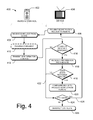
- FIG. 4 is a flow diagram of an illustrative process 400 for configuring a uniform universal remote and device in accordance with an embodiment of the disclosure.
- the process 400 includes elements associated with or preformed by either a remote control 402 or a device 404 , however, in some instances the elements may not be exclusive to either the remote control or device.
- the process 400 may begin at a block 406 where the device 404 transmits an identification request to the remote control 402 .
- the identification request may be transmitted by the ID detector 320 (e.g., a RFID scanner).
- the ID request is received by the remote control 402 .
- the remote control 402 may process the request received at the block 408 .
- the remote 402 may analyze the ID request via the controller 202 , which may access the memory 208 and/or the remote ID 210 .
- the remote control 402 may transmit ID information to the device 404 .
- the remote control 402 may include a RFID tag which may receive an ID request (at the block 408 ), and transmit ID information (at the block 412 ), such as a remote type and a remote ID code to the device.
- the process 400 further includes a decision block 414 to determine if the device 404 received a response to the request from the block 406 . If the process 400 determines that the device 404 received a response, the process continues to a block 416 to receive the ID information from the remote control 402 . In such an instance, the process 400 continues to a second decision block 418 where the process determines if the device 404 recognizes the remote control 402 . If the process 400 determines that the device 404 recognizes the remote control 402 , the process proceeds to a block 420 where the device is configured to process control signals from the remote control.
- the process 400 is directed along a route 422 to a decision block 424 .
- the decision block 424 determines if the process will ‘try again,’ or otherwise try to automatically configure the device 404 to communicate with the remote control 402 . If the process 400 attempts to configure the device again, the process proceeds along a route 426 back to the block 406 and the process begins again. Otherwise, the process 400 advances to a block 428 where the device 404 is manually configured. For example, the device may be manually configured by entering a remote control code into the device 404 though the user interface 314 .
- the device 404 may be in communication with a network, such as the Internet.
- the device 404 may submit a request or query to the network when configuring a remote, such as remote 402 , that is not recognized by the device.
- the request may occur in real-time or near real-time.
- the network may enable configuring the device 404 to operate with the remote 402 , such as by transmitting to the device 404 the information necessary to configure the remote 402 .
- the remote 402 may operate in a basic mode (e.g., default mode) when it is undetected by the device 404 .
- the remote 402 running in a basic mode may only operate basic remote control functions such as providing remote on/off and up/down controls (e.g., channel change for TV, scene skip for DVD, song skip for CD). Other basic operations are also contemplated.
- a customer may be offered selection of the basic mode as an option if automatic recognition fails.
- a user may locate the remote control 402 within a predetermined range from the device 404 , such that the device can communicate with the remote control.
- the range may be determined by the capabilities of the communication method, such that a first range may exist for transmitting Bluetooth® signals, a second range may exist for transmitting RFID signals, and so on.
- the device 404 may be activated to detect the remote control.
- the user may trigger the device 404 to detect the remote control 402 , such as by pressing a button on the device.
- the device 404 may continually transmit a communication signal to the remote control 402 at predetermined intervals, such that no action is necessary from the user to configure the remote control.
- FIG. 5 is a flow diagram of an illustrative operation 500 of a uniform universal remote and device showing configuration and control of the remote control and/or device.
- the process 500 includes a configuration process 502 and an operation process 504 , each described in turn.
- the configuration process 502 is similar to the configuration process shown in FIG. 4 , and therefore only additional features will be described.
- the remote control 402 determines the user and/or priority of the remote control.
- the remote control 402 may use the additional controls 118 , such as a finger scanner, to determine the identity of a user operating the remote control.
- the remote control may be assumed to belong to a specific user, such as a child in a family household.
- the remote 402 may also accept a personal identification number (PIN) which may be used to identify a user.
- PIN personal identification number
- the remote 402 may prompt the user to enter a PIN, such as by a display on the remote 402 or a display on the device 404 .
- the user information may impact the processing of control signals from the remote control 402 .
- the priority of the remote control 402 may allow the control signal of a first remote control to be implemented when a second control signal from a second remote control is received substantially simultaneously or within a specified time range, such as 10 seconds. Prioritization may reduce confusion or ‘dueling of remote controls,’ such as an instance that may occur between children competing over control of a television.
- the configuration process 502 may be stored in the storage medium 316 .
- the device 404 may attempt to locate a configured remote control 402 based on information stored in the storage medium 316 .
- the storage medium 316 may allow the device 404 to be configured with multiple remote controls, such as one for each family member or multiple universal remote controls for an entertainment system.
- the operation process 504 includes a block 508 where the remote control 402 transmits a control signal to the device 404 .
- the control signal may be a command to change the channel of a television.
- the device 404 receives the signal from the remote control 402 .
- the device identifies the remote control.
- the device 404 may identify the priority of the remote control signal and/or the user of the remote control.
- the device 404 determines whether to process the request from block 508 .
- the operation process 504 may determine to process the signal at a block 516 , such as if the determined user or prioritization is allowed by the operation process 504 .
- the operation process may not allow a user, who is identified as a child under age 18, to view movies with an R-rating.
- the second remote control's control signal may not be processed if the first remote control's signal was processed first. In such instances where the operation process 504 does not process the signal, the signal is rejected at a block 518 .
- the remote control 402 may transmit to the device 404 a packet of information along with the control signal.
- the packet of information may contain the remote identification number (e.g., serial number), such as “remote 123456,” the remote control's type, such as “Universal Remote Type-A,” and any other relevant information including without limitation the priority and privileges associated with the remote control.
- the information may be stored on the device 404 , such as on the storage medium 316 for association with the remote identification number or other unique identifiers.
- the remote control 402 may include multiple operating modes, such as a basic and a multifunction operational mode.
- the basic operational mode may allow a user to change volume, channels, and other basic operations while a multifunction operational mode may allow a user to conduct more sophisticated operations such as view menus, use soft keys, display information on a remote control display, and program the device 404 .
- the embodiments of the disclosure as described above may allow the device 404 to be selectively operated by the remote control using the basic and/or the multifunction operational modes, and may include standardized remote control operations and control signals.
- a standardized chip (memory, etc.) may be integrated in the device 404 for configuring the remote control 402 , and thus performing the functions described here.
Abstract
Description
Claims (7)
Priority Applications (1)
| Application Number | Priority Date | Filing Date | Title |
|---|---|---|---|
| US11/865,903 US9241114B1 (en) | 2007-10-02 | 2007-10-02 | Uniform universal remote configuration |
Applications Claiming Priority (1)
| Application Number | Priority Date | Filing Date | Title |
|---|---|---|---|
| US11/865,903 US9241114B1 (en) | 2007-10-02 | 2007-10-02 | Uniform universal remote configuration |
Publications (1)
| Publication Number | Publication Date |
|---|---|
| US9241114B1 true US9241114B1 (en) | 2016-01-19 |
Family
ID=55071523
Family Applications (1)
| Application Number | Title | Priority Date | Filing Date |
|---|---|---|---|
| US11/865,903 Expired - Fee Related US9241114B1 (en) | 2007-10-02 | 2007-10-02 | Uniform universal remote configuration |
Country Status (1)
| Country | Link |
|---|---|
| US (1) | US9241114B1 (en) |
Cited By (4)
| Publication number | Priority date | Publication date | Assignee | Title |
|---|---|---|---|---|
| US20150103249A1 (en) * | 2013-10-10 | 2015-04-16 | Samsung Electronics Co., Ltd. | Display apparatus and control method thereof |
| US20160142157A1 (en) * | 2013-06-18 | 2016-05-19 | Powervoice Co., Ltd. | Mobile device and method for outputting sound wave for control of external device, and external device |
| US20170264931A1 (en) * | 2013-11-04 | 2017-09-14 | Rovi Guides, Inc. | Systems and methods for recommending content |
| US20200021876A1 (en) * | 2009-09-29 | 2020-01-16 | Universal Electronics Inc. | System and method for reconfiguration of an entertainment system controlling device |
Citations (14)
| Publication number | Priority date | Publication date | Assignee | Title |
|---|---|---|---|---|
| US5386251A (en) * | 1993-06-03 | 1995-01-31 | Zilog, Inc. | Television receiver with learning remote control system capable of being controlled by a remote control device manufactured by different companies |
| US6538595B1 (en) * | 2000-01-26 | 2003-03-25 | Scientific-Atlanta, Inc. | System and method for using infrared remote control packet delivery in a wireless keyboard having a pointing device |
| US20050166240A1 (en) * | 2004-01-02 | 2005-07-28 | Lg Electronics Inc. | Display system and control method thereof |
| US20050202871A1 (en) * | 2004-01-26 | 2005-09-15 | Lippincott Louis A. | Multiple player game system, methods and apparatus |
| US20060129458A1 (en) * | 2000-10-12 | 2006-06-15 | Maggio Frank S | Method and system for interacting with on-demand video content |
| WO2007072314A1 (en) * | 2005-12-23 | 2007-06-28 | Koninklijke Philips Electronics N.V. | User interface with position awareness |
| US20070165555A1 (en) * | 2004-02-29 | 2007-07-19 | Netac Technology Co., Ltd. | Wireless control systems for digital household appliance |
| US20070296552A1 (en) * | 1998-07-23 | 2007-12-27 | Universal Electronics Inc. | System and method for setting up a universal remote control |
| US20080006696A1 (en) * | 2006-07-06 | 2008-01-10 | Ricoh Company, Ltd. | Programmatic control of RFID tags |
| US20080151126A1 (en) * | 2006-12-20 | 2008-06-26 | Amtran Technology Co., Ltd. | Remote control having audio-visual function |
| US20080157993A1 (en) * | 2006-12-27 | 2008-07-03 | General Instrument Corporation | Method and System for Pairing Electronic Devices |
| US7639115B2 (en) * | 2002-02-11 | 2009-12-29 | Somfy Sas | Method for matching bidirectional objects |
| US7719438B2 (en) * | 2006-10-10 | 2010-05-18 | Sony Corporation | System and method for universal remote control |
| US8823485B2 (en) * | 2007-01-22 | 2014-09-02 | Intel Mobile Communications GmbH | Programmable remote control unit and method |
-
2007
- 2007-10-02 US US11/865,903 patent/US9241114B1/en not_active Expired - Fee Related
Patent Citations (15)
| Publication number | Priority date | Publication date | Assignee | Title |
|---|---|---|---|---|
| US5386251A (en) * | 1993-06-03 | 1995-01-31 | Zilog, Inc. | Television receiver with learning remote control system capable of being controlled by a remote control device manufactured by different companies |
| US20070296552A1 (en) * | 1998-07-23 | 2007-12-27 | Universal Electronics Inc. | System and method for setting up a universal remote control |
| US6538595B1 (en) * | 2000-01-26 | 2003-03-25 | Scientific-Atlanta, Inc. | System and method for using infrared remote control packet delivery in a wireless keyboard having a pointing device |
| US20060129458A1 (en) * | 2000-10-12 | 2006-06-15 | Maggio Frank S | Method and system for interacting with on-demand video content |
| US7639115B2 (en) * | 2002-02-11 | 2009-12-29 | Somfy Sas | Method for matching bidirectional objects |
| US20050166240A1 (en) * | 2004-01-02 | 2005-07-28 | Lg Electronics Inc. | Display system and control method thereof |
| US20050202871A1 (en) * | 2004-01-26 | 2005-09-15 | Lippincott Louis A. | Multiple player game system, methods and apparatus |
| US20070165555A1 (en) * | 2004-02-29 | 2007-07-19 | Netac Technology Co., Ltd. | Wireless control systems for digital household appliance |
| US20090002981A1 (en) * | 2005-12-23 | 2009-01-01 | Koninklijke Philips Electronics N.V. | User Interface with Position Awareness |
| WO2007072314A1 (en) * | 2005-12-23 | 2007-06-28 | Koninklijke Philips Electronics N.V. | User interface with position awareness |
| US20080006696A1 (en) * | 2006-07-06 | 2008-01-10 | Ricoh Company, Ltd. | Programmatic control of RFID tags |
| US7719438B2 (en) * | 2006-10-10 | 2010-05-18 | Sony Corporation | System and method for universal remote control |
| US20080151126A1 (en) * | 2006-12-20 | 2008-06-26 | Amtran Technology Co., Ltd. | Remote control having audio-visual function |
| US20080157993A1 (en) * | 2006-12-27 | 2008-07-03 | General Instrument Corporation | Method and System for Pairing Electronic Devices |
| US8823485B2 (en) * | 2007-01-22 | 2014-09-02 | Intel Mobile Communications GmbH | Programmable remote control unit and method |
Cited By (12)
| Publication number | Priority date | Publication date | Assignee | Title |
|---|---|---|---|---|
| US20200021876A1 (en) * | 2009-09-29 | 2020-01-16 | Universal Electronics Inc. | System and method for reconfiguration of an entertainment system controlling device |
| US11076196B2 (en) * | 2009-09-29 | 2021-07-27 | Universal Electronics Inc. | System and method for reconfiguration of an entertainment system controlling device |
| US11252463B2 (en) * | 2009-09-29 | 2022-02-15 | Universal Electronics Inc. | System and method for reconfiguration of an entertainment system controlling device |
| US11533530B2 (en) | 2009-09-29 | 2022-12-20 | Universal Electronics Inc. | System and method for reconfiguration of an entertainment system controlling device |
| US11825147B2 (en) | 2009-09-29 | 2023-11-21 | Universal Electronics Inc. | System and method for reconfiguration of an entertainment system controlling device |
| US20160142157A1 (en) * | 2013-06-18 | 2016-05-19 | Powervoice Co., Ltd. | Mobile device and method for outputting sound wave for control of external device, and external device |
| US10243675B2 (en) * | 2013-06-18 | 2019-03-26 | Powervoice Co., Ltd. | Mobile device and method for outputting sound wave for control of external device, and external device |
| US20150103249A1 (en) * | 2013-10-10 | 2015-04-16 | Samsung Electronics Co., Ltd. | Display apparatus and control method thereof |
| CN105612759A (en) * | 2013-10-10 | 2016-05-25 | 三星电子株式会社 | Display apparatus and control method thereof |
| US9762946B2 (en) * | 2013-10-10 | 2017-09-12 | Samsung Electronics Co., Ltd. | Display apparatus and control method thereof |
| US20170264931A1 (en) * | 2013-11-04 | 2017-09-14 | Rovi Guides, Inc. | Systems and methods for recommending content |
| US10735790B2 (en) * | 2013-11-04 | 2020-08-04 | Rovi Guides, Inc. | Systems and methods for recommending content |
Similar Documents
| Publication | Publication Date | Title |
|---|---|---|
| US11410542B2 (en) | System and method for optimized appliance control | |
| US11700327B2 (en) | System and method for provision of appliance control functionality to a smart device | |
| US9252848B2 (en) | Apparatus, systems and methods for pairing a controlled device with an RF remote control using an RFID tag | |
| EP2731349B1 (en) | Display apparatus, voice acquiring apparatus and voice recognition method thereof | |
| US7769370B2 (en) | Method and system for pairing electronic devices | |
| US8299889B2 (en) | Home entertainment system providing presence and mobility via remote control authentication | |
| US7023498B2 (en) | Remote-controlled apparatus, a remote control system, and a remote-controlled image-processing apparatus | |
| US7436346B2 (en) | System, method and interface for controlling multiple electronic devices of a home entertainment system via a single control device | |
| US20140095174A1 (en) | Electronic device, server and control method thereof | |
| US20110077751A1 (en) | Systems and methods for controlling appliances via a network | |
| CN107635214B (en) | Response method, device, system and readable storage medium storing program for executing based on blue Tooth remote controller | |
| KR20120078071A (en) | Control device and method for control of broadcast reciever | |
| US9241114B1 (en) | Uniform universal remote configuration | |
| US20230394956A1 (en) | System and method for optimized appliance control | |
| KR20160138708A (en) | Auto pairing method and system between the IPTV set-top box and a Bluetooth remote controller | |
| KR101545904B1 (en) | Image display apparatus, and method for operating the same | |
| US8049593B2 (en) | Universal remote control apparatus and method based on service profiles | |
| US20150254503A1 (en) | Display apparatus and controlling method thereof | |
| US11830283B2 (en) | Apparatus and method for biometric control of a set top box | |
| US20180053402A1 (en) | Systems and methods for limiting remote-control device mode changes | |
| KR102654415B1 (en) | Display device and operating method thereof | |
| US20210218591A1 (en) | System and method for optimized appliance utilization | |
| JP2021092612A (en) | Command control device, control method and control program |
Legal Events
| Date | Code | Title | Description |
|---|---|---|---|
| AS | Assignment |
Owner name: AT&T BLS INTELLECTUAL PROPERTY, INC., DELAWARE Free format text: ASSIGNMENT OF ASSIGNORS INTEREST;ASSIGNOR:MCQUAIDE, JR., ARNOLD CHESTER;REEL/FRAME:019907/0677 Effective date: 20071002 |
|
| ZAAA | Notice of allowance and fees due |
Free format text: ORIGINAL CODE: NOA |
|
| ZAAB | Notice of allowance mailed |
Free format text: ORIGINAL CODE: MN/=. |
|
| AS | Assignment |
Owner name: AT&T INTELLECTUAL PROPERTY I, L.P., GEORGIA Free format text: ASSIGNMENT OF ASSIGNORS INTEREST;ASSIGNOR:AT&T DELAWARE INTELLECTUAL PROPERTY, INC.;REEL/FRAME:036618/0866 Effective date: 20130508 Owner name: AT&T DELAWARE INTELLECTUAL PROPERTY, INC., GEORGIA Free format text: CHANGE OF NAME;ASSIGNOR:AT&T BLS INTELLECTUAL PROPERTY, INC.;REEL/FRAME:036645/0036 Effective date: 20071101 |
|
| FEPP | Fee payment procedure |
Free format text: PAYOR NUMBER ASSIGNED (ORIGINAL EVENT CODE: ASPN); ENTITY STATUS OF PATENT OWNER: LARGE ENTITY |
|
| STCF | Information on status: patent grant |
Free format text: PATENTED CASE |
|
| MAFP | Maintenance fee payment |
Free format text: PAYMENT OF MAINTENANCE FEE, 4TH YEAR, LARGE ENTITY (ORIGINAL EVENT CODE: M1551); ENTITY STATUS OF PATENT OWNER: LARGE ENTITY Year of fee payment: 4 |
|
| FEPP | Fee payment procedure |
Free format text: MAINTENANCE FEE REMINDER MAILED (ORIGINAL EVENT CODE: REM.); ENTITY STATUS OF PATENT OWNER: LARGE ENTITY |
|
| LAPS | Lapse for failure to pay maintenance fees |
Free format text: PATENT EXPIRED FOR FAILURE TO PAY MAINTENANCE FEES (ORIGINAL EVENT CODE: EXP.); ENTITY STATUS OF PATENT OWNER: LARGE ENTITY |
|
| STCH | Information on status: patent discontinuation |
Free format text: PATENT EXPIRED DUE TO NONPAYMENT OF MAINTENANCE FEES UNDER 37 CFR 1.362 |
|
| FP | Lapsed due to failure to pay maintenance fee |
Effective date: 20240119 |