US9794720B1 - Acoustic position measurement - Google Patents
Acoustic position measurement Download PDFInfo
- Publication number
- US9794720B1 US9794720B1 US15/273,679 US201615273679A US9794720B1 US 9794720 B1 US9794720 B1 US 9794720B1 US 201615273679 A US201615273679 A US 201615273679A US 9794720 B1 US9794720 B1 US 9794720B1
- Authority
- US
- United States
- Prior art keywords
- microphone
- speaker
- equipped device
- playback
- playback system
- Prior art date
- Legal status (The legal status is an assumption and is not a legal conclusion. Google has not performed a legal analysis and makes no representation as to the accuracy of the status listed.)
- Active
Links
Images


Classifications
-
- H—ELECTRICITY
- H04—ELECTRIC COMMUNICATION TECHNIQUE
- H04S—STEREOPHONIC SYSTEMS
- H04S7/00—Indicating arrangements; Control arrangements, e.g. balance control
- H04S7/30—Control circuits for electronic adaptation of the sound field
- H04S7/301—Automatic calibration of stereophonic sound system, e.g. with test microphone
-
- H—ELECTRICITY
- H04—ELECTRIC COMMUNICATION TECHNIQUE
- H04R—LOUDSPEAKERS, MICROPHONES, GRAMOPHONE PICK-UPS OR LIKE ACOUSTIC ELECTROMECHANICAL TRANSDUCERS; DEAF-AID SETS; PUBLIC ADDRESS SYSTEMS
- H04R1/00—Details of transducers, loudspeakers or microphones
- H04R1/20—Arrangements for obtaining desired frequency or directional characteristics
- H04R1/32—Arrangements for obtaining desired frequency or directional characteristics for obtaining desired directional characteristic only
- H04R1/40—Arrangements for obtaining desired frequency or directional characteristics for obtaining desired directional characteristic only by combining a number of identical transducers
- H04R1/406—Arrangements for obtaining desired frequency or directional characteristics for obtaining desired directional characteristic only by combining a number of identical transducers microphones
-
- H—ELECTRICITY
- H04—ELECTRIC COMMUNICATION TECHNIQUE
- H04R—LOUDSPEAKERS, MICROPHONES, GRAMOPHONE PICK-UPS OR LIKE ACOUSTIC ELECTROMECHANICAL TRANSDUCERS; DEAF-AID SETS; PUBLIC ADDRESS SYSTEMS
- H04R27/00—Public address systems
-
- H—ELECTRICITY
- H04—ELECTRIC COMMUNICATION TECHNIQUE
- H04R—LOUDSPEAKERS, MICROPHONES, GRAMOPHONE PICK-UPS OR LIKE ACOUSTIC ELECTROMECHANICAL TRANSDUCERS; DEAF-AID SETS; PUBLIC ADDRESS SYSTEMS
- H04R3/00—Circuits for transducers, loudspeakers or microphones
- H04R3/005—Circuits for transducers, loudspeakers or microphones for combining the signals of two or more microphones
-
- H—ELECTRICITY
- H04—ELECTRIC COMMUNICATION TECHNIQUE
- H04R—LOUDSPEAKERS, MICROPHONES, GRAMOPHONE PICK-UPS OR LIKE ACOUSTIC ELECTROMECHANICAL TRANSDUCERS; DEAF-AID SETS; PUBLIC ADDRESS SYSTEMS
- H04R3/00—Circuits for transducers, loudspeakers or microphones
- H04R3/04—Circuits for transducers, loudspeakers or microphones for correcting frequency response
-
- H—ELECTRICITY
- H04—ELECTRIC COMMUNICATION TECHNIQUE
- H04R—LOUDSPEAKERS, MICROPHONES, GRAMOPHONE PICK-UPS OR LIKE ACOUSTIC ELECTROMECHANICAL TRANSDUCERS; DEAF-AID SETS; PUBLIC ADDRESS SYSTEMS
- H04R3/00—Circuits for transducers, loudspeakers or microphones
- H04R3/12—Circuits for transducers, loudspeakers or microphones for distributing signals to two or more loudspeakers
-
- H—ELECTRICITY
- H04—ELECTRIC COMMUNICATION TECHNIQUE
- H04R—LOUDSPEAKERS, MICROPHONES, GRAMOPHONE PICK-UPS OR LIKE ACOUSTIC ELECTROMECHANICAL TRANSDUCERS; DEAF-AID SETS; PUBLIC ADDRESS SYSTEMS
- H04R5/00—Stereophonic arrangements
- H04R5/02—Spatial or constructional arrangements of loudspeakers
-
- H—ELECTRICITY
- H04—ELECTRIC COMMUNICATION TECHNIQUE
- H04S—STEREOPHONIC SYSTEMS
- H04S7/00—Indicating arrangements; Control arrangements, e.g. balance control
- H04S7/30—Control circuits for electronic adaptation of the sound field
- H04S7/302—Electronic adaptation of stereophonic sound system to listener position or orientation
- H04S7/303—Tracking of listener position or orientation
-
- H—ELECTRICITY
- H04—ELECTRIC COMMUNICATION TECHNIQUE
- H04R—LOUDSPEAKERS, MICROPHONES, GRAMOPHONE PICK-UPS OR LIKE ACOUSTIC ELECTROMECHANICAL TRANSDUCERS; DEAF-AID SETS; PUBLIC ADDRESS SYSTEMS
- H04R2203/00—Details of circuits for transducers, loudspeakers or microphones covered by H04R3/00 but not provided for in any of its subgroups
- H04R2203/12—Beamforming aspects for stereophonic sound reproduction with loudspeaker arrays
-
- H—ELECTRICITY
- H04—ELECTRIC COMMUNICATION TECHNIQUE
- H04R—LOUDSPEAKERS, MICROPHONES, GRAMOPHONE PICK-UPS OR LIKE ACOUSTIC ELECTROMECHANICAL TRANSDUCERS; DEAF-AID SETS; PUBLIC ADDRESS SYSTEMS
- H04R2227/00—Details of public address [PA] systems covered by H04R27/00 but not provided for in any of its subgroups
- H04R2227/003—Digital PA systems using, e.g. LAN or internet
-
- H—ELECTRICITY
- H04—ELECTRIC COMMUNICATION TECHNIQUE
- H04R—LOUDSPEAKERS, MICROPHONES, GRAMOPHONE PICK-UPS OR LIKE ACOUSTIC ELECTROMECHANICAL TRANSDUCERS; DEAF-AID SETS; PUBLIC ADDRESS SYSTEMS
- H04R2227/00—Details of public address [PA] systems covered by H04R27/00 but not provided for in any of its subgroups
- H04R2227/005—Audio distribution systems for home, i.e. multi-room use
-
- H—ELECTRICITY
- H04—ELECTRIC COMMUNICATION TECHNIQUE
- H04R—LOUDSPEAKERS, MICROPHONES, GRAMOPHONE PICK-UPS OR LIKE ACOUSTIC ELECTROMECHANICAL TRANSDUCERS; DEAF-AID SETS; PUBLIC ADDRESS SYSTEMS
- H04R2420/00—Details of connection covered by H04R, not provided for in its groups
- H04R2420/07—Applications of wireless loudspeakers or wireless microphones
-
- H—ELECTRICITY
- H04—ELECTRIC COMMUNICATION TECHNIQUE
- H04S—STEREOPHONIC SYSTEMS
- H04S2400/00—Details of stereophonic systems covered by H04S but not provided for in its groups
- H04S2400/13—Aspects of volume control, not necessarily automatic, in stereophonic sound systems
Definitions
- This disclosure is related to consumer goods and, more particularly, to methods, systems, products, features, services, and other elements directed to media playback or some aspect thereof.
- the Sonos Wireless HiFi System enables people to experience music from many sources via one or more networked playback devices. Through a software control application installed on a smartphone, tablet, or computer, one can play what he or she wants in any room that has a networked playback device. Additionally, using the controller, for example, different songs can be streamed to each room with a playback device, rooms can be grouped together for synchronous playback, or the same song can be heard in all rooms synchronously.
- FIG. 1 shows an example media playback system configuration in which certain embodiments may be practiced
- FIG. 2 shows a functional block diagram of an example playback device
- FIG. 3 shows a functional block diagram of an example control device
- FIG. 4 shows an example controller interface
- FIG. 5 shows an example plurality of network devices
- FIG. 6 shows a functional block diagram of an example network microphone device
- FIG. 7A shows aspects of a system and method for determining a position of a speaker-equipped device relative to a plurality of microphone-equipped devices in an example media playback system.
- FIG. 7B shows another example illustration of determining a position of a speaker-equipped device relative to a microphone-equipped device of a media playback system based at least in part on a test sound(s) emitted from the speaker-equipped device.
- FIG. 7C shows an illustration of using the position information obtained in the procedures described with reference to FIGS. 7A and/or 7B to configure beamforming parameters for a microphone array of a networked microphone device.
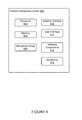
- FIG. 8 shows a method 800 that can be implemented within an operating environment including or involving, for example, the media playback system 100 of FIG. 1 , one or more playback devices 200 of FIG. 2 , one or more control devices 300 of FIG. 3 , the user interface of FIG. 4 , the configuration shown in FIG. 5 , the NMD shown in FIG. 6 , and/or the media playback system 700 shown in FIGS. 7A-C .
- An example speaker-equipped device may be a control device (e.g., a smartphone or tablet computer), a networked microphone device (NMD), or a playback device that plays audio.
- An example listening environment may be a home theater, living room, bedroom, or even the outdoor space of a home.
- An example NMD may be a SONOS® playback device, server, or system capable of receiving voice inputs via a microphone.
- an NMD may be a device other than a SONOS® playback device, server, or system (e.g., AMAZON® ECHO®, APPLE® IPHONE®) capable of receiving voice inputs via a microphone.
- SONOS® playback device server, or system
- AMAZON® ECHO®, APPLE® IPHONE® capable of receiving voice inputs via a microphone.
- U.S. application Ser. No. 15/098,867 entitled, “Default Playback Device Designation,” which is hereby incorporated by reference, provides examples of voice-enabled household architectures.
- Knowing the position of the playback devices in a listening environment may be useful in providing the best audio experience.
- placing a playback device too close or too far from a listener or orienting the direction of the playback device sub-optimally may impact quality of the audio sound heard by a listener.
- the audio may sound distorted, undesirably attenuated, or undesirably amplified based on the position of the listener relative to the playback device.
- the audio playback device can adjust the audio sound to optimize the audio experience.
- knowing the position of the playback devices a listener can readjust the position of the playback devices to optimize the audio experience.
- Determining the position of the playback devices may sometimes be referred to as spatial mapping.
- a control device may display a user interface to facilitate the calibration of a playback device or an NMD for spatial mapping.
- Some calibration procedures involve control devices detecting sound waves (e.g., one or more test sounds) emitted by one or more playback devices of the media playback system.
- some calibration procedures may include spectral and/or spatial calibration.
- a processing device such as a computing device that is communicatively coupled to the media playback system, may determine a first calibration that configures one or more playback devices to a given listening area spectrally. Such a calibration may generally help offset acoustic characteristics of the listening environment and may be applied during certain use cases, such as music playback.
- the processing device may also determine a second calibration that configures the one or more playback devices to a given listening area spatially (and perhaps also spectrally). Such a calibration may configure the one or more playback devices to one or more particular locations within the listening environment (e.g., one or more preferred listening positions, such as favorite seating location), perhaps by adjusting time-delay and/or loudness for those particular locations. This second calibration may be applied during other use cases, such as home theater.
- U.S. application Ser. No. 15/005,853 entitled, “Calibration with Particular Locations,” which is hereby incorporated by reference, provides example techniques to facilitate calibration of the media playback system.
- Example calibration procedures may involve a microphone-equipped device detecting sound waves (e.g., one or more test sounds) emitted by a speaker-equipped device (e.g., control device) of the media playback system.
- the microphone-equipped device (or any other device or system described herein) may analyze the detected sound waves to determine the position of the speaker-equipped device relative to one or more microphone-equipped devices.
- determining the position of the speaker-equipped device relative to the microphone-equipped device may involve determining an angle of the speaker-equipped device relative to the microphone-equipped device. Additionally or alternatively, determining the position of the speaker-equipped device relative to the microphone-equipped device may involve determining a distance between the speaker-equipped device and the microphone equipped device.
- the media playback system may adjust one or more audio configuration parameters to further optimize and improve audio experience. For example, based on the position of the control device relative to one or more microphone-equipped devices, audio configuration parameters such as equalization, gain, and attenuation, of one or more playback devices can be adjusted or calibrated through audio processing algorithms, filters, disabling playback devices, enabling playback devices, and the sort.
- the microphone-equipped device may (i) facilitate discovery of a particular location within the listening environment that provides the best audio experience, (ii) facilitate adjustment of the position of the speaker-equipped device (e.g., control device) during an audio calibration procedure to optimize the audio experience, and/or (iii) facilitate amplification of sound in the direction of a speaker-equipped device or a preferred location within a listening environment.
- FIG. 1 shows an example configuration of a media playback system 100 in which one or more embodiments disclosed herein may be practiced or implemented.
- the media playback system 100 as shown is associated with an example home environment having several rooms and spaces, such as for example, a master bedroom, an office, a dining room, and a living room.
- the media playback system 100 includes playback devices 102 - 124 , control devices 126 and 128 , and a wired or wireless network router 130 .
- FIG. 2 shows a functional block diagram of an example playback device 200 that may be configured to be one or more of the playback devices 102 - 124 of the media playback system 100 of FIG. 1 .
- the playback device 200 may include a processor 202 , software components 204 , memory 206 , audio processing components 208 , audio amplifier(s) 210 , speaker(s) 212 , a network interface 214 including wireless interface(s) 216 and wired interface(s) 218 , and microphone(s) 220 .
- the playback device 200 may not include the speaker(s) 212 , but rather a speaker interface for connecting the playback device 200 to external speakers.
- the playback device 200 may include neither the speaker(s) 212 nor the audio amplifier(s) 210 , but rather an audio interface for connecting the playback device 200 to an external audio amplifier or audio-visual receiver.
- the processor 202 may be a clock-driven computing component configured to process input data according to instructions stored in the memory 206 .
- the memory 206 may be a tangible computer-readable medium configured to store instructions executable by the processor 202 .
- the memory 206 may be data storage that can be loaded with one or more of the software components 204 executable by the processor 202 to achieve certain functions.
- the functions may involve the playback device 200 retrieving audio data from an audio source or another playback device.
- the functions may involve the playback device 200 sending audio data to another device or playback device on a network.
- the functions may involve pairing of the playback device 200 with one or more playback devices to create a multi-channel audio environment.
- Certain functions may involve the playback device 200 synchronizing playback of audio content with one or more other playback devices.
- a listener will preferably not be able to perceive time-delay differences between playback of the audio content by the playback device 200 and the one or more other playback devices.
- the memory 206 may further be configured to store data associated with the playback device 200 , such as one or more zones and/or zone groups the playback device 200 is a part of, audio sources accessible by the playback device 200 , or a playback queue that the playback device 200 (or some other playback device) may be associated with.
- the data may be stored as one or more state variables that are periodically updated and used to describe the state of the playback device 200 .
- the memory 206 may also include the data associated with the state of the other devices of the media system, and shared from time to time among the devices so that one or more of the devices have the most recent data associated with the system. Other embodiments are also possible.
- the audio processing components 208 may include one or more digital-to-analog converters (DAC), an audio preprocessing component, an audio enhancement component or a digital signal processor (DSP), and so on. In one embodiment, one or more of the audio processing components 208 may be a subcomponent of the processor 202 . In one example, audio content may be processed and/or intentionally altered by the audio processing components 208 to produce audio signals. The produced audio signals may then be provided to the audio amplifier(s) 210 for amplification and playback through speaker(s) 212 . Particularly, the audio amplifier(s) 210 may include devices configured to amplify audio signals to a level for driving one or more of the speakers 212 .
- DAC digital-to-analog converters
- DSP digital signal processor
- the speaker(s) 212 may include an individual transducer (e.g., a “driver”) or a complete speaker system involving an enclosure with one or more drivers.
- a particular driver of the speaker(s) 212 may include, for example, a subwoofer (e.g., for low frequencies), a mid-range driver (e.g., for middle frequencies), and/or a tweeter (e.g., for high frequencies).
- each transducer in the one or more speakers 212 may be driven by an individual corresponding audio amplifier of the audio amplifier(s) 210 .
- the audio processing components 208 may be configured to process audio content to be sent to one or more other playback devices for playback.
- Audio content to be processed and/or played back by the playback device 200 may be received from an external source, such as via an audio line-in input connection (e.g., an auto-detecting 3.5 mm audio line-in connection) or the network interface 214 .
- an audio line-in input connection e.g., an auto-detecting 3.5 mm audio line-in connection
- the network interface 214 e.g., the Internet
- the network interface 214 may be configured to facilitate a data flow between the playback device 200 and one or more other devices on a data network.
- the playback device 200 may be configured to receive audio content over the data network from one or more other playback devices in communication with the playback device 200 , network devices within a local area network, or audio content sources over a wide area network such as the Internet.
- the audio content and other signals transmitted and received by the playback device 200 may be transmitted in the form of digital packet data containing an Internet Protocol (IP)-based source address and IP-based destination addresses.
- IP Internet Protocol
- the network interface 214 may be configured to parse the digital packet data such that the data destined for the playback device 200 is properly received and processed by the playback device 200 .
- the network interface 214 may include wireless interface(s) 216 and wired interface(s) 218 .
- the wireless interface(s) 216 may provide network interface functions for the playback device 200 to wirelessly communicate with other devices (e.g., other playback device(s), speaker(s), receiver(s), network device(s), control device(s) within a data network the playback device 200 is associated with) in accordance with a communication protocol (e.g., any wireless standard including IEEE 802.11a, 802.11b, 802.11g, 802.11n, 802.11ac, 802.15, 4G mobile communication standard, and so on).
- a communication protocol e.g., any wireless standard including IEEE 802.11a, 802.11b, 802.11g, 802.11n, 802.11ac, 802.15, 4G mobile communication standard, and so on.
- the wired interface(s) 218 may provide network interface functions for the playback device 200 to communicate over a wired connection with other devices in accordance with a communication protocol (e.g., IEEE 802.3). While the network interface 214 shown in FIG. 2 includes both wireless interface(s) 216 and wired interface(s) 218 , the network interface 214 may in some embodiments include only wireless interface(s) or only wired interface(s).
- a communication protocol e.g., IEEE 802.3
- the microphone(s) 220 may be arranged to detect sound in the environment of the playback device 200 .
- the microphone(s) may be mounted on an exterior wall of a housing of the playback device.
- the microphone(s) may be any type of microphone now known or later developed such as a condenser microphone, electret condenser microphone, or a dynamic microphone.
- the microphone(s) may be sensitive to a portion of the frequency range of the speaker(s) 220 .
- the microphone(s) 220 may include an array of microphones, where one or more processors associated with the microphone (e.g., processor 202 or other processor(s)) are configured to implement beamforming capabilities with the array of microphones. Additionally, or alternatively, one or more of the speaker(s) 212 may operate in reverse as the microphone(s) 220 .
- the playback device 200 might not include the microphone(s) 220 .
- the playback device 200 and one other playback device may be paired to play two separate audio components of audio content.
- playback device 200 may be configured to play a left channel audio component, while the other playback device may be configured to play a right channel audio component, thereby producing or enhancing a stereo effect of the audio content.
- the paired playback devices (also referred to as “bonded playback devices”) may further play audio content in synchrony with other playback devices.
- the playback device 200 may be sonically consolidated with one or more other playback devices to form a single, consolidated playback device.
- a consolidated playback device may be configured to process and reproduce sound differently than an unconsolidated playback device or playback devices that are paired, because a consolidated playback device may have additional speaker drivers through which audio content may be rendered. For instance, if the playback device 200 is a playback device designed to render low frequency range audio content (e.g., a subwoofer), the playback device 200 may be consolidated with a playback device designed to render full frequency range audio content.
- low frequency range audio content e.g., a subwoofer
- the full frequency range playback device when consolidated with the low frequency playback device 200 , may be configured to render only the mid and high frequency components of audio content, while the low frequency range playback device 200 renders the low frequency component of the audio content.
- the consolidated playback device may further be paired with a single playback device or yet another consolidated playback device.
- a playback device is not limited to the example illustrated in FIG. 2 or to the SONOS product offerings.
- a playback device may include a wired or wireless headphone.
- a playback device may include or interact with a docking station for personal mobile media playback devices.
- a playback device may be integral to another device or component such as a television, a lighting fixture, or some other device for indoor or outdoor use.
- the environment may have one or more playback zones, each with one or more playback devices.
- the media playback system 100 may be established with one or more playback zones, after which one or more zones may be added, or removed to arrive at the example configuration shown in FIG. 1 .
- Each zone may be given a name according to a different room or space such as an office, bathroom, master bedroom, bedroom, kitchen, dining room, living room, and/or balcony.
- a single playback zone may include multiple rooms or spaces.
- a single room or space may include multiple playback zones.
- the balcony, dining room, kitchen, bathroom, office, and bedroom zones each have one playback device, while the living room and master bedroom zones each have multiple playback devices.
- playback devices 104 , 106 , 108 , and 110 may be configured to play audio content in synchrony as individual playback devices, as one or more bonded playback devices, as one or more consolidated playback devices, or any combination thereof.
- playback devices 122 and 124 may be configured to play audio content in synchrony as individual playback devices, as a bonded playback device, or as a consolidated playback device.
- one or more playback zones in the environment of FIG. 1 may each be playing different audio content.
- the user may be grilling in the balcony zone and listening to hip hop music being played by the playback device 102 while another user may be preparing food in the kitchen zone and listening to classical music being played by the playback device 114 .
- a playback zone may play the same audio content in synchrony with another playback zone.
- the user may be in the office zone where the playback device 118 is playing the same rock music that is being playing by playback device 102 in the balcony zone.
- playback devices 102 and 118 may be playing the rock music in synchrony such that the user may seamlessly (or at least substantially seamlessly) enjoy the audio content that is being played out-loud while moving between different playback zones. Synchronization among playback zones may be achieved in a manner similar to that of synchronization among playback devices, as described in previously referenced U.S. Pat. No. 8,234,395.
- the zone configurations of the media playback system 100 may be dynamically modified, and in some embodiments, the media playback system 100 supports numerous configurations. For instance, if a user physically moves one or more playback devices to or from a zone, the media playback system 100 may be reconfigured to accommodate the change(s). For instance, if the user physically moves the playback device 102 from the balcony zone to the office zone, the office zone may now include both the playback device 118 and the playback device 102 . The playback device 102 may be paired or grouped with the office zone and/or renamed if so desired via a control device such as the control devices 126 and 128 . On the other hand, if the one or more playback devices are moved to a particular area in the home environment that is not already a playback zone, a new playback zone may be created for the particular area.
- different playback zones of the media playback system 100 may be dynamically combined into zone groups or split up into individual playback zones.
- the dining room zone and the kitchen zone 114 may be combined into a zone group for a dinner party such that playback devices 112 and 114 may render audio content in synchrony.
- the living room zone may be split into a television zone including playback device 104 , and a listening zone including playback devices 106 , 108 , and 110 , if the user wishes to listen to music in the living room space while another user wishes to watch television.
- FIG. 3 shows a functional block diagram of an example control device 300 that may be configured to be one or both of the control devices 126 and 128 of the media playback system 100 .
- the control device 300 may include a processor 302 , memory 304 , a network interface 306 , a user interface 308 , microphone(s) 310 , and software components 312 .
- the control device 300 may be a dedicated controller for the media playback system 100 .
- the control device 300 may be a network device on which media playback system controller application software may be installed, such as for example, an iPhoneTM, iPadTM or any other smart phone, tablet or network device (e.g., a networked computer such as a PC or MacTM).
- the processor 302 may be configured to perform functions relevant to facilitating user access, control, and configuration of the media playback system 100 .
- the memory 304 may be data storage that can be loaded with one or more of the software components executable by the processor 302 to perform those functions.
- the memory 304 may also be configured to store the media playback system controller application software and other data associated with the media playback system 100 and the user.
- the network interface 306 may be based on an industry standard (e.g., infrared, radio, wired standards including IEEE 802.3, wireless standards including IEEE 802.11a, 802.11b, 802.11g, 802.11n, 802.11ac, 802.15, 4G mobile communication standard, and so on).
- the network interface 306 may provide a means for the control device 300 to communicate with other devices in the media playback system 100 .
- data and information (e.g., such as a state variable) may be communicated between control device 300 and other devices via the network interface 306 .
- playback zone and zone group configurations in the media playback system 100 may be received by the control device 300 from a playback device or another network device, or transmitted by the control device 300 to another playback device or network device via the network interface 306 .
- the other network device may be another control device.
- Playback device control commands such as volume control and audio playback control may also be communicated from the control device 300 to a playback device via the network interface 306 .
- changes to configurations of the media playback system 100 may also be performed by a user using the control device 300 .
- the configuration changes may include adding/removing one or more playback devices to/from a zone, adding/removing one or more zones to/from a zone group, forming a bonded or consolidated player, separating one or more playback devices from a bonded or consolidated player, among others.
- the control device 300 may sometimes be referred to as a controller, whether the control device 300 is a dedicated controller or a network device on which media playback system controller application software is installed.
- Control device 300 may include microphone(s) 310 .
- Microphone(s) 310 may be arranged to detect sound in the environment of the control device 300 .
- Microphone(s) 310 may be any type of microphone now known or later developed such as a condenser microphone, electret condenser microphone, or a dynamic microphone.
- the microphone(s) may be sensitive to a portion of a frequency range.
- Two or more microphones 310 may be arranged to capture location information of an audio source (e.g., voice, audible sound) and/or to assist in filtering background noise.
- an audio source e.g., voice, audible sound
- the user interface 308 of the control device 300 may be configured to facilitate user access and control of the media playback system 100 , by providing a controller interface such as the controller interface 400 shown in FIG. 4 .
- the controller interface 400 includes a playback control region 410 , a playback zone region 420 , a playback status region 430 , a playback queue region 440 , and an audio content sources region 450 .
- the user interface 400 as shown is just one example of a user interface that may be provided on a network device such as the control device 300 of FIG. 3 (and/or the control devices 126 and 128 of FIG. 1 ) and accessed by users to control a media playback system such as the media playback system 100 .
- Other user interfaces of varying formats, styles, and interactive sequences may alternatively be implemented on one or more network devices to provide comparable control access to a media playback system.
- the playback control region 410 may include selectable (e.g., by way of touch or by using a cursor) icons to cause playback devices in a selected playback zone or zone group to play or pause, fast forward, rewind, skip to next, skip to previous, enter/exit shuffle mode, enter/exit repeat mode, enter/exit cross fade mode.
- the playback control region 410 may also include selectable icons to modify equalization settings, and playback volume, among other possibilities.
- the playback zone region 420 may include representations of playback zones within the media playback system 100 .
- the graphical representations of playback zones may be selectable to bring up additional selectable icons to manage or configure the playback zones in the media playback system, such as a creation of bonded zones, creation of zone groups, separation of zone groups, and renaming of zone groups, among other possibilities.
- a “group” icon may be provided within each of the graphical representations of playback zones.
- the “group” icon provided within a graphical representation of a particular zone may be selectable to bring up options to select one or more other zones in the media playback system to be grouped with the particular zone.
- playback devices in the zones that have been grouped with the particular zone will be configured to play audio content in synchrony with the playback device(s) in the particular zone.
- a “group” icon may be provided within a graphical representation of a zone group. In this case, the “group” icon may be selectable to bring up options to deselect one or more zones in the zone group to be removed from the zone group.
- Other interactions and implementations for grouping and ungrouping zones via a user interface such as the user interface 400 are also possible.
- the representations of playback zones in the playback zone region 420 may be dynamically updated as playback zone or zone group configurations are modified.
- the playback status region 430 may include graphical representations of audio content that is presently being played, previously played, or scheduled to play next in the selected playback zone or zone group.
- the selected playback zone or zone group may be visually distinguished on the user interface, such as within the playback zone region 420 and/or the playback status region 430 .
- the graphical representations may include track title, artist name, album name, album year, track length, and other relevant information that may be useful for the user to know when controlling the media playback system via the user interface 400 .
- the playback queue region 440 may include graphical representations of audio content in a playback queue associated with the selected playback zone or zone group.
- each playback zone or zone group may be associated with a playback queue containing information corresponding to zero or more audio items for playback by the playback zone or zone group.
- each audio item in the playback queue may comprise a uniform resource identifier (URI), a uniform resource locator (URL) or some other identifier that may be used by a playback device in the playback zone or zone group to find and/or retrieve the audio item from a local audio content source or a networked audio content source, possibly for playback by the playback device.
- URI uniform resource identifier
- URL uniform resource locator
- a playlist may be added to a playback queue, in which case information corresponding to each audio item in the playlist may be added to the playback queue.
- audio items in a playback queue may be saved as a playlist.
- a playback queue may be empty, or populated but “not in use” when the playback zone or zone group is playing continuously streaming audio content, such as Internet radio that may continue to play until otherwise stopped, rather than discrete audio items that have playback durations.
- a playback queue can include Internet radio and/or other streaming audio content items and be “in use” when the playback zone or zone group is playing those items. Other examples are also possible.
- playback queues associated with the affected playback zones or zone groups may be cleared or re-associated. For example, if a first playback zone including a first playback queue is grouped with a second playback zone including a second playback queue, the established zone group may have an associated playback queue that is initially empty, that contains audio items from the first playback queue (such as if the second playback zone was added to the first playback zone), that contains audio items from the second playback queue (such as if the first playback zone was added to the second playback zone), or a combination of audio items from both the first and second playback queues.
- the resulting first playback zone may be re-associated with the previous first playback queue, or be associated with a new playback queue that is empty or contains audio items from the playback queue associated with the established zone group before the established zone group was ungrouped.
- the resulting second playback zone may be re-associated with the previous second playback queue, or be associated with a new playback queue that is empty, or contains audio items from the playback queue associated with the established zone group before the established zone group was ungrouped.
- Other examples are also possible.
- the graphical representations of audio content in the playback queue region 440 may include track titles, artist names, track lengths, and other relevant information associated with the audio content in the playback queue.
- graphical representations of audio content may be selectable to bring up additional selectable icons to manage and/or manipulate the playback queue and/or audio content represented in the playback queue. For instance, a represented audio content may be removed from the playback queue, moved to a different position within the playback queue, or selected to be played immediately, or after any currently playing audio content, among other possibilities.
- a playback queue associated with a playback zone or zone group may be stored in a memory on one or more playback devices in the playback zone or zone group, on a playback device that is not in the playback zone or zone group, and/or some other designated device.
- the audio content sources region 450 may include graphical representations of selectable audio content sources from which audio content may be retrieved and played by the selected playback zone or zone group. Discussions pertaining to audio content sources may be found in the following section.
- one or more playback devices in a zone or zone group may be configured to retrieve for playback audio content (e.g. according to a corresponding URI or URL for the audio content) from a variety of available audio content sources.
- audio content may be retrieved by a playback device directly from a corresponding audio content source (e.g., a line-in connection).
- audio content may be provided to a playback device over a network via one or more other playback devices or network devices.
- Example audio content sources may include a memory of one or more playback devices in a media playback system such as the media playback system 100 of FIG. 1 , local music libraries on one or more network devices (such as a control device, a network-enabled personal computer, or a networked-attached storage (NAS), for example), streaming audio services providing audio content via the Internet (e.g., the cloud), or audio sources connected to the media playback system via a line-in input connection on a playback device or network devise, among other possibilities.
- a media playback system such as the media playback system 100 of FIG. 1
- network devices such as a control device, a network-enabled personal computer, or a networked-attached storage (NAS), for example
- streaming audio services providing audio content via the Internet (e.g., the cloud)
- audio content sources may be regularly added or removed from a media playback system such as the media playback system 100 of FIG. 1 .
- an indexing of audio items may be performed whenever one or more audio content sources are added, removed or updated. Indexing of audio items may involve scanning for identifiable audio items in all folders/directory shared over a network accessible by playback devices in the media playback system, and generating or updating an audio content database containing metadata (e.g., title, artist, album, track length, among others) and other associated information, such as a URI or URL for each identifiable audio item found. Other examples for managing and maintaining audio content sources may also be possible.
- FIG. 5 shows an example plurality of devices 500 that may be configured to provide an audio playback experience based on voice control.
- the devices shown in FIG. 5 are for illustrative purposes only, and variations including different and/or additional devices may be possible.
- the plurality of devices 500 includes computing devices 504 , 506 , and 508 ; network microphone devices (NMDs) 512 , 514 , and 516 ; playback devices (PBDs) 532 , 534 , 536 , and 538 ; and a controller device (CR) 522 .
- NMDs network microphone devices
- PBDs playback devices
- CR controller device
- Each of the plurality of devices 500 may be network-capable devices that can establish communication with one or more other devices in the plurality of devices according to one or more network protocols, such as NFC, Bluetooth, Ethernet, and IEEE 802.11, among other examples, over one or more types of networks, such as wide area networks (WAN), local area networks (LAN), and personal area networks (PAN), among other possibilities.
- network protocols such as NFC, Bluetooth, Ethernet, and IEEE 802.11, among other examples, over one or more types of networks, such as wide area networks (WAN), local area networks (LAN), and personal area networks (PAN), among other possibilities.
- WAN wide area networks
- LAN local area networks
- PAN personal area networks
- the computing devices 504 , 506 , and 508 may be part of a cloud network 502 .
- the cloud network 502 may include additional computing devices.
- the computing devices 504 , 506 , and 508 may be different servers.
- two or more of the computing devices 504 , 506 , and 508 may be modules of a single server.
- each of the computing device 504 , 506 , and 508 may include one or more modules or servers.
- each of the computing devices 504 , 506 , and 508 may be configured to perform particular functions within the cloud network 502 .
- computing device 508 may be a source of audio content for a streaming music service.
- the computing device 504 may be configured to interface with NMDs 512 , 514 , and 516 via communication path 542 .
- NMDs 512 , 514 , and 516 may be components of one or more “Smart Home” systems.
- NMDs 512 , 514 , and 516 may be physically distributed throughout a household, similar to the distribution of devices shown in FIG. 1 .
- two or more of the NMDs 512 , 514 , and 516 may be physically positioned within relative close proximity of one another.
- Communication path 542 may comprise one or more types of networks, such as a WAN including the Internet, LAN, and/or PAN, among other possibilities.
- one or more of the NMDs 512 , 514 , and 516 may be devices configured primarily for audio detection. In another example, one or more of the NMDs 512 , 514 , and 516 may be components of devices having various primary utilities. For instance, as discussed above in connection to FIGS. 2 and 3 , one or more of NMDs 512 , 514 , and 516 may be the microphone(s) 220 of playback device 200 or the microphone(s) 310 of network device 300 . Further, in some cases, one or more of NMDs 512 , 514 , and 516 may be the playback device 200 or network device 300 . In an example, one or more of NMDs 512 , 514 , and/or 516 may include multiple microphones arranged in a microphone array.
- the computing device 506 may be configured to interface with CR 522 and PBDs 532 , 534 , 536 , and 538 via communication path 544 .
- CR 522 may be a network device such as the network device 200 of FIG. 2 .
- CR 522 may be configured to provide the controller interface 400 of FIG. 4 or a similar controller interface for controlling one or more of PBDs 532 , 534 , 536 , and 538 and/or NMDs 512 , 514 , and 516 .
- PBDs 532 , 534 , 536 , and 538 may be playback devices such as the playback device 300 of FIG. 3 .
- PBDs 532 , 534 , 536 , and 538 may be physically distributed throughout a household as shown in FIG. 1 .
- PBDs 536 and 538 may be part of a bonded zone 530
- PBDs 532 and 534 may be part of their own respective zones.
- the PBDs 532 , 534 , 536 , and 538 may be dynamically bonded, grouped, unbonded, and ungrouped.
- Communication path 544 may comprise one or more types of networks, such as a WAN including the Internet, LAN, and/or PAN, among other possibilities.
- CR 522 and PBDs 532 , 534 , 536 , and 538 may also be components of one or more “Smart Home” systems.
- PBDs 532 , 534 , 536 , and 538 may be distributed throughout the same household as the NMDs 512 , 514 , and 516 .
- one or more of PBDs 532 , 534 , 536 , and 538 may be one or more of NMDs 512 , 514 , and 516 (or vice versa).
- the NMDs 512 , 514 , and 516 may be part of a local area network, and the communication path 542 may include an access point that links the local area network of the NMDs 512 , 514 , and 516 to the computing device 504 over a WAN (communication path not shown). Likewise, each of the NMDs 512 , 514 , and 516 may communicate with each other via such an access point.
- CR 522 and PBDs 532 , 534 , 536 , and 538 may be part of a local area network and/or a local playback network as discussed in previous sections, and the communication path 544 may include an access point that links the local area network and/or local playback network of CR 522 and PBDs 532 , 534 , 536 , and 538 to the computing device 506 over a WAN. As such, each of the CR 522 and PBDs 532 , 534 , 536 , and 538 may also communicate with each over such an access point.
- a single access point may include communication paths 542 and 544 .
- each of the NMDs 512 , 514 , and 516 , CR 522 , and PBDs 532 , 534 , 536 , and 538 may access the cloud network 502 via the same access point for a household.
- each of the NMDs 512 , 514 , and 516 , CR 522 , and PBDs 532 , 534 , 536 , and 538 may also directly communicate with one or more of the other devices via communication means 546 .
- Communication means 546 as described herein may involve one or more forms of communication between the devices, according to one or more network protocols, over one or more types of networks, and/or may involve communication via one or more other network devices.
- communication means 546 may include one or more of for example, BluetoothTM (IEEE 802.15), NFC, Wireless direct, and/or Proprietary wireless, among other possibilities.
- CR 522 may communicate with NMD 512 over BluetoothTM, and communicate with PBD 534 over another local area network.
- NMD 514 may communicate with CR 522 over another local area network, and communicate with PBD 536 over Bluetooth.
- each of the PBDs 532 , 534 , 536 , and 538 may communicate with each other according to a spanning tree protocol over a local playback network (or other routing and/or communication protocol), while each communicating with CR 522 over a local area network, different from the local playback network. Other examples are also possible.
- communication means between the NMDs 512 , 514 , and 516 , CR 522 , and PBDs 532 , 534 , 536 , and 538 may change depending on types of communication between the devices, network conditions, and/or latency demands.
- communication means 546 may be used when NMD 516 is first introduced to the household with the PBDs 532 , 534 , 536 , and 538 .
- the NMD 516 may transmit identification information corresponding to the NMD 516 to PBD 538 via NFC, and PBD 538 may in response, transmit local area network information to NMD 516 via NFC (or some other form of communication).
- NMD 516 may change. For instance, NMD 516 may subsequently communicate with PBD 538 via communication path 542 , the cloud network 502 , and communication path 544 .
- the NMDs and PBDs may never communicate via local communications means 546 .
- the NMDs and PBDs may communicate primarily via local communications means 546 . Other examples are also possible.
- NMDs 512 , 514 , and 516 may be configured to receive voice inputs to control PBDs 532 , 534 , 536 , and 538 .
- the available control commands may include any media playback system controls previously discussed, such as playback volume control, playback transport controls, music source selection, and grouping, among other possibilities.
- NMD 512 may receive a voice input to control one or more of the PBDs 532 , 534 , 536 , and 538 .
- NMD 512 may transmit via communication path 542 , the voice input to computing device 504 for processing.
- the computing device 504 may convert the voice input to an equivalent text command, and parse the text command to identify a command. Computing device 504 may then subsequently transmit the text command to the computing device 506 . In another example, the computing device 504 may convert the voice input to an equivalent text command, and then subsequently transmit the text command to the computing device 506 . The computing device 506 may then parse the text command to identify one or more playback commands.
- the computing device 506 may identify (i) a URL for “Track 1” by “Artist 1” available from “Streaming Service 1,” and (ii) at least one playback device in “Zone 1.”
- the URL for “Track 1” by “Artist 1” from “Streaming Service 1” may be a URL pointing to computing device 508
- “Zone 1” may be the bonded zone 530 .
- the computing device 506 may transmit via communication path 544 to one or both of PBDs 536 and 538 , the identified URL for playback.
- One or both of PBDs 536 and 538 may responsively retrieve audio content from the computing device 508 according to the received URL, and begin playing “Track 1” by “Artist 1” from “Streaming Service 1.”
- operations performed by one or more of the plurality of devices 500 may be performed by one or more other devices in the plurality of device 500 .
- the conversion from voice input to the text command may be alternatively, partially, or wholly performed by another device or devices, such as NMD 512 , computing device 506 , PBD 536 , and/or PBD 538 .
- the identification of the URL may be alternatively, partially, or wholly performed by another device or devices, such as NMD 512 , computing device 504 , PBD 536 , and/or PBD 538 .
- FIG. 6 shows a function block diagram of an example network microphone device 600 that may be configured to be one or more of NMDs 512 , 514 , and 516 of FIG. 5 .
- the network microphone device 600 includes a processor 602 , memory 604 , a microphone array 606 , a network interface 608 , a user interface 610 , software components 612 , and speaker(s) 614 .
- a processor 602 includes a processor 602 , memory 604 , a microphone array 606 , a network interface 608 , a user interface 610 , software components 612 , and speaker(s) 614 .
- network microphone devices may alternatively exclude the speaker(s) 614 or have a single microphone instead of microphone array 606 .
- the processor 602 may include one or more processors and/or controllers, which may take the form of a general or special-purpose processor or controller.
- the processing unit 602 may include microprocessors, microcontrollers, application-specific integrated circuits, digital signal processors, and the like.
- the memory 604 may be data storage that can be loaded with one or more of the software components executable by the processor 602 to perform those functions.
- memory 604 may comprise one or more non-transitory computer-readable storage mediums, examples of which may include volatile storage mediums such as random access memory, registers, cache, etc. and non-volatile storage mediums such as read-only memory, a hard-disk drive, a solid-state drive, flash memory, and/or an optical-storage device, among other possibilities.
- the microphone array 606 may be a plurality of microphones arranged to detect sound in the environment of the network microphone device 600 .
- Microphone array 606 may include any type of microphone now known or later developed such as a condenser microphone, electret condenser microphone, or a dynamic microphone, among other possibilities.
- the microphone array may be arranged to detect audio from one or more directions relative to the network microphone device.
- the microphone array 606 may be sensitive to a portion of a frequency range. In one example, a first subset of the microphone array 606 may be sensitive to a first frequency range, while a second subset of the microphone array may be sensitive to a second frequency range.
- the microphone array 606 may further be arranged to capture location information of an audio source (e.g., voice, audible sound) and/or to assist in filtering background noise.
- an audio source e.g., voice, audible sound
- the microphone array may consist of only a single microphone, rather than a plurality of microphones.
- the network interface 608 may be configured to facilitate wireless and/or wired communication between various network devices, such as, in reference to FIG. 5 , CR 522 , PBDs 532 - 538 , computing device 504 - 508 in cloud network 502 , and other network microphone devices, among other possibilities.
- network interface 608 may take any suitable form for carrying out these functions, examples of which may include an Ethernet interface, a serial bus interface (e.g., FireWire, USB 2.0, etc.), a chipset and antenna adapted to facilitate wireless communication, and/or any other interface that provides for wired and/or wireless communication.
- the network interface 608 may be based on an industry standard (e.g., infrared, radio, wired standards including IEEE 802.3, wireless standards including IEEE 802.11a, 802.11b, 802.11g, 802.11n, 802.11ac, 802.15, 4G mobile communication standard, and so on).
- an industry standard e.g., infrared, radio, wired standards including IEEE 802.3, wireless standards including IEEE 802.11a, 802.11b, 802.11g, 802.11n, 802.11ac, 802.15, 4G mobile communication standard, and so on.
- the user interface 610 of the network microphone device 600 may be configured to facilitate user interactions with the network microphone device.
- the user interface 608 may include one or more of physical buttons, graphical interfaces provided on touch sensitive screen(s) and/or surface(s), among other possibilities, for a user to directly provide input to the network microphone device 600 .
- the user interface 610 may further include one or more of lights and the speaker(s) 614 to provide visual and/or audio feedback to a user.
- the network microphone device 600 may further be configured to playback audio content via the speaker(s) 614 .
- an individual microphone-equipped device may be any of the herein-disclosed components that include one or more microphones (e.g., any playback device, networked microphone device, or controller with one or more microphones) and an individual speaker-equipped device may be any of the herein-disclosed components that include one or more speakers (e.g., any playback device, networked microphone device, or controller with one or more speakers).
- microphones e.g., any playback device, networked microphone device, or controller with one or more microphones
- an individual speaker-equipped device may be any of the herein-disclosed components that include one or more speakers (e.g., any playback device, networked microphone device, or controller with one or more speakers).
- the speaker-equipped device might be a controller device, e.g., controller 522 shown and described with reference to FIG. 5
- the microphone-equipped device might be a playback device, e.g., any of PBDs 532 , 534 , 536 , or 538 , as shown an described with reference to FIG. 5
- the speaker-equipped device may be a first playback device, and the microphone-equipped device may be a second playback device.
- the speaker-equipped device may be a playback device and the microphone-equipped device may be a networked microphone device.
- the speaker-equipped device may be a networked microphone device and the microphone-equipped device may be a playback device.
- Other arrangements of one or more playback devices, networked microphone devices, and/or controllers as the speaker-equipped and microphone-equipped devices are possible as well.
- FIG. 7A shows aspects of a system and method for determining a position of a speaker-equipped device relative to a plurality of microphone-equipped devices in an example media playback system 700 .
- the example media playback system 700 in FIG. 7A includes a plurality of playback devices 702 - 710 , a controller CR 712 , and a networked microphone device (NMD) 714 .
- NMD networked microphone device
- Embodiments may include more, fewer, or different components than the ones shown in the example media playback system 700 .
- the playback devices 702 - 710 of media playback system 700 are components of a surround sound system, where playback device 702 is or at least includes a left front speaker(s), playback device 704 is or at least includes a right front speaker(s), playback device 706 is or at least includes a center channel speaker(s), playback device 708 is or at least includes a left rear speaker(s), and playback device 710 is or at least includes a right rear speaker(s).
- One or more of the playback devices 702 - 710 may be similar to or the same as any of playback devices disclosed and described herein, e.g., playback devices 102 - 124 ( FIG. 1 ), playback device 200 ( FIG.
- one or more of the playback devices 702 - 710 may be also equipped with one or more microphones, and thus, one or more of the playback devices 702 - 710 may be considered either (or both) a speaker-equipped device and/or microphone-equipped device within the context of the features and functions performed by the systems and methods described herein.
- the controller CR 712 may be similar to or the same as any of the controller devices disclosed and described herein, e.g., controllers 126 - 128 ( FIG. 1 ), controller 300 ( FIG. 3 ) or CR 522 ( FIG. 5 ). In operation, CR 712 may be configured to display a user interface similar to or the same as the user interface shown and described with reference to FIG. 4 .
- the controller CR 712 may also include one or more microphones and/or one or more speakers, and thus, the controller CR 712 may be considered either (or both) a speaker-equipped device and/or a microphone-equipped device within the context of the features and functions performed by systems and methods described herein.
- NMD 714 may be similar to or the same as any of the networked microphone devices disclosed and described herein, e.g., NMDs 512 - 514 ( FIG. 5 ) or networked microphone device 600 ( FIG. 6 ).
- NMD 714 may include one or more microphones and/or one or more speakers, and thus, the NMD 714 may be considered either (or both) a speaker-equipped device or microphone-equipped device within the context of the features and functions performed by the systems and methods described herein.
- the media playback system 700 (or at least one component of the media playback system 700 ) first determines that position information of a speaker-equipped device is required, or at least desired.
- the controller CR 712 is a speaker-equipped device and the playback devices 702 - 710 (or at least one of the playback devices 702 - 710 ) are microphone-equipped devices.
- determining a requirement for position information of the speaker-equipped device amounts to determining the position of the controller CR 712 relative to at least one of the playback devices 702 - 710 .
- the determination that position information for CR 712 is required (or at least desired) can be made in response to one or more commands to perform a function for which position information for controller CR 712 is required, or at least desired.
- determining a requirement for position information of the speaker-equipped device comprises receiving a command to configure surround sound processing parameters of the media playback system 700 based on a position of the controller CR 712 .
- the media playback system 700 determines that position information of the controller CR 712 is required, or at least desired.
- determining a requirement for position information of the speaker-equipped device in the media playback system comprises receiving a command for a first playback device to form a stereo pair with a second playback device of the media playback system.
- controller CR 712 may receive a command to form a stereo pair with left front 702 and right front 704 playback devices.
- the media playback system 700 (or at least one or more components thereof) may determine that position information of the controller CR 712 is required.
- the media playback system 700 determines a position of the speaker-equipped device relative to at least one microphone-equipped device of the media playback system based at least in part on one or more test sounds emitted from the speaker-equipped device.
- Some embodiments may also include messaging between the speaker-equipped device and the one or more microphone-equipped device(s) before the speaker-equipped device begins emitting the test sound(s), and/or perhaps while the speaker-equipped device emits the test sound(s).
- the speaker-equipped device sends one or more control messages to one or more microphone-equipped devices in the media playback system 700 to (i) inform the microphone-equipped devices that the speaker-equipped device is about to begin emitting test sound(s) for spatial measurements and/or (ii) command the one or more microphone-equipped devices to listen for the test sound(s) for the purpose of conducting a spatial measurement.
- one or more microphone-equipped devices of the media playback system 700 sends one or more control messages to the speaker-equipped device to (i) inform the speaker-equipped device that a spatial measurement is required, and/or (ii) command the speaker-equipped device to emit test sound(s) for the purpose of conducting the spatial measurement.
- the one or more control messages exchanged between the speaker-equipped device and the one or more microphone-equipped device(s) may further include a presentation timestamp to indicate a time when the speaker-equipped device will play (or has already played) the test sound(s) for detection by the one or more microphone-equipped devices.
- the media playback system 700 uses the presentation timestamp to perform time delay calculations associated with determining, for an individual microphone-equipped device, the angle to and distance from the speaker-equipped device.
- Some embodiments may further include the speaker-equipped device(s) and/or the microphone-equipped device(s) indicating to a user that a spatial measurement is about to begin and/or is in progress.
- the indication may be an audible indication (e.g., a notification played via a speaker on the speaker-equipped device(s) and/or the microphone-equipped device(s)) or a visible indication (e.g., a flashing and/or colored light on the speaker-equipped device(s) and/or the microphone-equipped device(s)), an indication within a user interface application running on a controller).
- the device to be located plays the test sounds(s) during the location determination procedure.
- the test sound(s) may be in the audible or inaudible frequency range.
- the frequency or frequencies used for the test sound should be within a frequency range capable of reproduction by one or more speakers of the speaker-equipped device(s) and a frequency range capable of detection by one or more microphones of the microphone-equipped device(s).
- test sounds emitted by each speaker-equipped device should be different in frequency and/or time, e.g., pulsating tones, different pulsing rates, tones played at different times, and so on, so that the microphone-equipped device(s) can distinguish between the test sounds emitted by the different speaker-equipped devices.
- the test sound may comprise music or other media played by one or more of the speaker-equipped devices.
- the test sound(s) emitted from the speaker-equipped device may take the form of, for example, a test signal, sound, test tone (e.g., ultrasonic tone), pulse, rhythm, frequency or frequencies, or audio pattern.
- the frequency range may include a range of frequencies that the playback device is capable of emitting (e.g., 15-30,000 Hz) and may be inclusive of frequencies that are considered to be in the range of human hearing (e.g., 20-20,000 Hz).
- the pulse may be a recording of a brief audio pulse that approximates an audio impulse signal. Some examples include recordings of an electric spark, a starter pistol shot, or the bursting of a balloon.
- the audio signal may include a signal that varies over frequency, such as a logarithmic chirp, a sine sweep, a pink noise signal, or a maximum length sequence.
- a signal that varies over frequency such as a logarithmic chirp, a sine sweep, a pink noise signal, or a maximum length sequence.
- Such signals may be chosen for relatively broader-range coverage of the frequency spectrum or for other reasons.
- the test sound may involve other types of audio signals as well.
- the test sound may have a particular waveform.
- the waveform may correspond to any of the example test sounds described above, such as, an electric spark, a starter pistol shot, or the bursting of a balloon.
- the speaker-equipped device may store the first audio signal as a recording and play it back during the position determination procedure.
- the recording may take a variety of audio file formats, such as a waveform audio file format (WAV) or an MPEG-2 audio layer III (MP3), among other examples.
- WAV waveform audio file format
- MP3 MPEG-2 audio layer III
- the speaker-equipped device may dynamically generate the audio signal. For instance, the speaker-equipped device may generate a signal that varies over frequency according to a mathematical equation. Other examples are possible as well.
- the microphone-equipped device should know the test sound(s) that the speaker-equipped device will use for the position determination process.
- the speaker-equipped device sends a data file comprising the test sound(s) to the microphone-equipped device(s) so that the microphone-equipped devices will know the test sound(s) they are listening for.
- some embodiments include one or more of the microphone-equipped devices sending a data file comprising the test sound(s) to the speaker-equipped device. And after receiving the data file comprising the test sound(s), the speaker-equipped device plays the test sound(s).
- both the speaker-equipped device and the microphone-equipped device(s) receive the test sound(s) that will be used for the position determination from another computing device, e.g., one or more of computing devices 504 - 508 ( FIG. 5 ).
- the speaker-equipped device and the microphone-equipped device(s) can each obtain the test sound(s) from a network location via a uniform resource identifier (URI), uniform resource locator (URL), and/or an index or path for a file stored at a location accessible by at least one of the speaker-equipped device and/or the microphone-equipped device(s).
- URI uniform resource identifier
- URL uniform resource locator
- the speaker-equipped device and the microphone-equipped device(s) may receive a set of test sound parameters for a tone generator (e.g., a software-based tone generator) located on at least the speaker-equipped device and possibly also the microphone-equipped device(s). After receiving the parameters for the tone generator, the speaker-equipped device then uses the received parameters to generate the test sound(s).
- a tone generator e.g., a software-based tone generator
- the speaker-equipped device sends a data file comprising the test sound parameters to the microphone-equipped device(s) so that the microphone-equipped device(s) will know the test sound(s) that the speaker-equipped device will generate.
- some embodiments include one or more of the microphone-equipped devices sending a data file comprising the test sound parameters to the speaker-equipped device. And after receiving the data file comprising the test sound parameters, the speaker-equipped device configures the tone generator with the test sound parameters, generates the test sound(s), and plays the test sound(s) via one or more speakers.
- both the speaker-equipped device and the microphone-equipped device(s) receive test sound parameters that will be used by a tone generator at the speaker-equipped device for the position determination from another computing device, e.g., one or more of computing devices 504 - 508 ( FIG. 5 ).
- the speaker-equipped device and the microphone-equipped device(s) can each obtain the test sound parameters from a network location via a uniform resource identifier (URI), uniform resource locator (URL), and/or an index or path for a file stored at a location accessible by at least one of the speaker-equipped device and/or the microphone-equipped device(s).
- URI uniform resource identifier
- URL uniform resource locator
- the speaker-equipped device plays the test sound(s) and the microphone-equipped device(s) detect the test sound(s) emitted from the speaker-equipped device.
- the controller CR 712 i.e., a speaker-equipped device
- plays the test sound(s) and one or more of the playback devices 702 - 710 i.e., microphone-equipped devices
- the microphone-equipped device(s) may also analyze the detected test sound(s) emitted from the speaker-equipped device to determine the position of the speaker-equipped device, but in other embodiments, the microphone-equipped device(s) may alternatively send the captured test sound(s) to one or more computing devices for analysis, e.g., computing devices 504 - 508 ( FIG. 5 ), or even the controller CR 712 .
- determining a position of the speaker-equipped device relative to a microphone-equipped device of the media playback system based at least in part on the test sound(s) emitted from the speaker-equipped device comprises determining (i) an angle of the speaker-equipped device relative to the microphone-equipped device and (ii) a distance between the speaker-equipped device and the microphone-equipped device.
- the media playback system 700 may determine the position of a speaker-equipped device relative to a microphone-equipped device while the media playback device is playing media. Alternatively, the media playback system 700 may stop playing media while determining the position of the speaker-equipped device relative to the microphone-equipped device to prevent (or at least reduce) acoustic interference with the position measurement.
- the left front 702 playback device determines the position of controller CR 712 based at least in part on a test sound(s) emitted from the controller CR 712 by determining (i) the angle 716 of the controller CR 712 relative to the left front 702 playback device and (ii) the distance 718 between the controller CR 712 and the left front 702 playback device.
- each of the other playback devices 706 - 710 may also determine its own relative angle to and distance from the controller CR 712 based at least in part on the test sound(s) emitted from the controller CR 712 .
- center 706 may determine angle 724 to and distance 726 from controller CR 712 ;
- right front 704 may determine angle 720 to and distance 722 from controller CR 712 ;
- left rear 708 may determine angle 728 to and distance 730 from controller CR 712 ;
- right rear 710 may determine angle 732 to and distance 734 from controller CR 712 .
- each playback device may record the test sound emitted by the controller CR 712 and send the recorded sound to one or more computing devices for analysis, e.g., computing devices 504 - 508 ( FIG. 5 ), or even the controller CR 712 .
- one of the playback devices (e.g., left front 702 ) is configured as a master playback device for the media playback system 700
- each of the other playback devices (e.g., 704 - 710 ) are configured as slave playback devices.
- the master e.g., 702
- the master may determine the angle (e.g., 716 ) to and distance (e.g., 718 ) from the controller CR 712
- each of the slave playback devices e.g., 704 - 710
- each of the slave playback devices may send a recording of the sound emitted by the controller CR 712 to the master playback device (e.g., 702 ) for analysis and determination of the relative angles (e.g., 720 , 724 , 728 , and 732 ) and distances (e.g., 722 , 726 , 730 , and 732 ) between the slave playback devices and the controller CR 712 .
- each microphone-equipped device has a microphone array comprising two or more microphones, and the microphone-equipped device uses the test sound(s) detected by the microphone array to determine the angle to and distance from a speaker-equipped device.
- each of the microphone-equipped device(s) knows the position of each microphone in its microphone array relative to the “front” and/or “center” of the microphone-equipped device.
- the program code for determining the position of the speaker-equipped device relative to the left front 702 playback device includes information about the position of the microphones of the microphone array of the left front 702 playback device, e.g., where those microphones are located on the left front 702 playback device relative to the front and/or center of the left front 702 playback device.
- the single microphone on each of the two microphone-equipped devices can be used as a microphone array for determining the position of the speaker-equipped device relative to a virtual line connecting the two microphone-equipped devices.
- the controller CR 712 is the speaker-equipped device and left front 702 and right front 704 playback devices each have only a single microphone
- the left front 702 and right front 704 playback devices can perform synchronized detection of the test sound(s) emitted by the controller CR 712 .
- the media playback system 700 (or one or more components thereof) determine the distance of the virtual line between the left front 702 playback device and the right front 704 playback device according to the methods described herein with reference to Equation 2, explained in more detail below.
- the media playback system 700 can determine the position of the controller CR 712 relative to the center of a virtual line joining the left front 702 and left right 704 playback devices.
- the media playback system 700 (or one or more components thereof) can use both (i) the position of the left front 702 and right front 704 playback devices relative to each other and (ii) the position of the controller CR 712 relative to the center of the virtual line joining the left front 702 and right front 704 playback devices to determine the angle to and distance from the controller CR 712 for both the left front 702 and right front 704 playback devices.
- each of the microphone-equipped device(s) whose individual microphones comprise the microphone array knows the position of its microphone relative to the “front” and/or “center” of the microphone-equipped device.
- the program code for determining the position of the speaker-equipped device relative to the left front 702 playback device includes information about the position of the microphone of the left front 702 playback device, e.g., where the microphone is located on the left front 702 playback device relative to the front and/or center of the left front 702 playback device.
- the program code for determining the position of the speaker-equipped device relative to the right front 704 playback device includes information about the position of the microphone of the right front 704 playback device, e.g., where the microphone is located on the right front 704 playback device relative to the front and/or center of the right front 704 playback device.
- device clocks of each of the microphone-equipped devices whose individual microphones comprise the microphone array ideally are synchronized (preferably to within a single sample accuracy) to improve the accuracy of the position measurements.
- both microphone-equipped devices are playback devices that are configured play back audio in synchrony with each other, each playback device can rely upon timing information derived from their synchronous playback protocol rather than timing information derived from synchronized device clocks.
- determining the angle of the speaker-equipped device relative to the microphone-equipped device comprises solving for Equation 1:
- Equation 1 ⁇ is the angle of the speaker-equipped device relative to the microphone-equipped device, t d is a measurement of delay between when a test sound is detected by a first microphone of the microphone-equipped device and when the test sound is detected by a second microphone of the microphone-equipped device, v s is a speed of sound constant, and d mm is the distance between the first and second microphones of the microphone-equipped device.
- determining the angle 716 of the controller CR 712 relative to the left front 702 playback device includes solving for Equation 1, where ⁇ is the angle 716 of the controller CR 712 relative to the left front 702 playback device, t d is a measurement of delay between when a test sound emitted from the controller CR 712 is detected by a first microphone of the left front 702 playback device and when the test sound emitted from the controller CR 712 is detected by a second microphone of the left front 702 playback device, v s is a speed of sound constant, and d mm is the distance between the first and second microphones of the left front 702 playback device.
- the media playback system 700 determines the difference between (i) when the first microphone detected the test sound(s) and (ii) when the second microphone detected the test sound(s).
- a microphone-equipped device can determine when a particular microphone detects a test sound via a number of methods.
- a microphone-equipped device can determine when a particular microphone (e.g., the first or second microphone) detects a test sound based on sound pressure level, by quantifying a point in time where sound pressure level corresponding to the test sound increases above some threshold level.
- a microphone-equipped device individually or in combination with other computing devices, may additionally or alternatively apply a Fast Fourier Transform (FFT) and/or an Inverse Fast Fourier Transform (IFFT) on a received sound signal to determine a time (e.g., with reference to a device clock) when a particular microphone detects a test sound.
- FFT Fast Fourier Transform
- IFFT Inverse Fast Fourier Transform
- controller CR 522 may emit one or more test sounds, and the microphone-equipped devices (or any other device described herein) may analyze the frequency, amplitude, and phase of the one or more test sounds.
- the microphone-equipped devices may analyze a frequency and/or time domain representation of the detected test sound in order to determine the start of when CR 522 emits the one or more test sounds. Other examples to determine the start of when CR 522 emits the one or more tests sounds are possible. If the speaker-equipped device emits a plurality of test sounds for the position determination, then the signals detected by each microphone can be analyzed to determine when (e.g., to within a particular device clock sample time) the test sound first appeared in each signal detected by each microphone of the microphone array.
- d is the distance between the speaker-equipped device and the microphone-equipped device
- v s is a speed of sound constant
- transmission delay is a measurement of delay between when a test sound is detected by the microphone-equipped device and when the test sound was played by the speaker-equipped device.
- determining the distance 718 between the controller CR 712 and the left front 702 playback device includes solving for Equation 2, where d is the distance 718 between the controller CR 712 and the left front 702 playback device, v s is a speed of sound constant, and transmission delay is a measurement of delay between (i) the time that a test sound emitted by the controller CR 712 is detected by the left front 702 playback device and (ii) the time the test sound was emitted by the controller CR 712 .
- the device clock of the controller CR 712 may be synchronized with the device clock of the front left 702 playback device to within a single-sample accuracy to improve the precision of (i) the t d measurement of Equation 1 and (ii) the transmission delay measurement of Equation 2.
- synchronization of device clocks between the speaker-equipped device and the microphone-equipped device may not be necessary.
- the speaker-equipped device and the microphone-equipped device are both playback devices in the media playback system 700 configured for synchronous media playback, the speaker-equipped device and the microphone-equipped device may rely upon timing information derived from their synchronous playback protocol to obtain an accurate measurement for t d in Equation 1 and transmission delay in Equation 2, even though the microphone-equipped device and speaker-equipped device in such embodiments are, or at least may be, independently clocked.
- the speaker-equipped device and the one or more microphone-equipped devices exchange one or more control messages that include a presentation timestamp to indicate a time when the speaker-equipped device will play (or has already played) the test sound(s) for detection by the one or more microphone-equipped devices.
- the speaker-equipped device plays the test sound(s) at the time indicated in the presentation timestamp.
- a microphone-equipped device detects the start of the test sound at a microphone of the microphone-equipped device according to any of the methods for detecting the start of a test sound described above.
- the microphone-equipped device (individually or perhaps in combination with one or more other computing devices) can then calculate the distance between the microphone-equipped device and an individual speaker-equipped device by (i) subtracting the presentation timestamp from the detection time, thereby yielding a transmission delay and (ii) calculating the distance from speaker-equipped device to the microphone-equipped device by multiplying the calculated transmission delay by the value of the speed of sound constant, v s .
- some embodiments further include configuring one or more audio configuration parameters of the media playback system 700 based on the position of the speaker-equipped device relative to the one or more microphone-equipped devices. For example, after front left 702 playback device determines the position of the controller CR 712 relative to front left 702 playback device, the front left 702 playback device may configure one or more sound processing parameters of the front left 702 playback device and perhaps other playback devices of the media playback system 700 .
- some of the parameters that may be configured based on the determined angles and distances include equalization, surround sound parameters, and/or stereo parameters.
- an application running on the controller CR 712 instructs a user to stand or sit in a preferred location where he or she typically watches movies, television, or other content with surround sound encoded media.
- the media playback system 700 performs the above-described procedure to determine the position of the controller CR 712 relative to one or more of the playback devices 702 - 710 .
- the media playback system 700 may then use the position information of the controller CR 712 at the preferred location to configure one or more audio configuration parameters the playback devices 702 - 710 so that the “acoustic center” of the media played by the playback devices 702 - 710 is aligned with the preferred location.
- the “acoustic center” means the location where the surround sound effect is focused, such that a user at that position will (or at least should) hear the optimal (or at least a very good) separation between the different surround sound channels.
- the “acoustic center” is the location where the user should hear very good (perhaps even optimal) separation between the five channels, i.e., left front, center, right front, left rear, and right rear.
- configuring one or more audio configuration parameters of the media playback system 700 based on the position of the speaker-equipped device (e.g., controller CR 712 ) relative to the microphone-equipped device(s) comprises configuring one or more of a volume and/or delay processing parameter for one or more speakers of one or more of the playback devices 702 - 710 in media playback system 700 such that the “acoustic center” of surround sound media played by the media playback system 700 is aligned with the position of the controller CR 712 when the media playback system 700 determined the position of the controller CR 712 .
- an application running on the controller CR 712 instructs a user to stand or sit in a preferred location where he or she typically listens to standard two-channel stereo music.
- the media playback system 700 performs the above-described procedure to determine the position of the controller CR 712 relative to the left front 702 playback device and the right front 704 playback device.
- the media playback system 700 may then use the position information of the controller CR 712 at the preferred location to configure one or more audio configuration parameters of the left front 702 and right front 704 playback devices so that the “acoustic center” of stereo music played by the media playback system 700 is aligned with the preferred location.
- the “acoustic center” means the location where the stereo sound effect is focused, such that a user at that position will (or at least should) hear the optimal (or at least a very good) separation between the stereo channels.
- the “acoustic center” is the location where the user should hear very good (perhaps even optimal) separation between left and right channels.
- configuring one or more audio configuration parameters of the media playback system 700 based on the position of the speaker-equipped device (e.g., controller CR 712 ) relative to the left front 702 and right front 704 playback devices comprises configuring one or more of a volume and/or delay processing parameter for one or more speakers of the left front 702 and right front 704 playback devices.
- the left front 702 and left rear 708 playback devices may be bonded together and configured to play left channel stereo content and the right front 704 and right rear 710 may be bonded together to play right channel stereo content.
- the “acoustic center” is the location where the user should hear very good (perhaps even optimal) separation between the four quadraphonic stereo channels, e.g., left front, right front, left rear, right rear, or perhaps other quadraphonic channels.
- configuring one or more audio configuration parameters of the media playback system 700 based on the position of the speaker-equipped device (e.g., controller CR 712 ) relative to the left front 702 , right front 704 , left rear 708 , and right rear 710 playback devices comprises configuring one or more of a volume and/or delay processing parameter for one or more speakers of the left front 702 , right front 704 , left rear 78 , and right rear 710 playback devices.
- the preferred location associated with the above-described surround sound configuration may be different than the preferred location associated with the above-described stereo configuration. But in some embodiments, the preferred location for surround sound and stereo might be the same, and in such embodiments, the media playback system 700 may use the same preferred location for configuring the audio configuration parameters for both surround sound and stereo operation.
- position information for the speaker-equipped device may also be used with spectral calibration procedures for measuring or otherwise characterizing the frequency response of a room in which the media playback system 700 is operating. Measuring or otherwise characterizing the frequency response of a room may be helpful in identifying which frequencies the room tends to attenuate and which frequencies the room tends to amplify or accentuate. Once the frequency response of the room is known, equalization and/or other audio playback parameters for one or more playback devices 702 - 710 of the media playback system 700 can be adjusted to compensate for the frequencies that the room tends to attenuate or amplify in order to improve the listening experience.
- the spectral calibration procedure may be the Sonos Trueplay calibration procedure. But other spectral calibration procedures could be used instead.
- the media playback system 700 (or at least one or more components thereof) first determines a requirement (or at least a desire) for position information of one or more speaker-equipped devices in connection with a spectral calibration procedure.
- determining a requirement for position information of the speaker-equipped device in the media playback system comprises receiving a command to initiate a spatial calibration procedure for the media playback system, wherein the spatial calibration procedure comprises the first playback device playing one or more audio calibration tones.
- multiple (or even all) of the playback devices 702 - 710 may play the one or more audio calibration tones.
- each playback device might play the same audio calibration tones. In other embodiments, each playback device might play different audio calibration tones.
- the media playback system 700 (or at least one or more playback devices 702 - 710 therein) tracks the position of the controller CR 712 during the Trueplay procedure (or other spectral calibration procedure). Tracking the position of the controller CR 712 during the Trueplay or other spectral calibration procedure may be helpful for instructing a user where to move the controller CR 712 during the procedure to help improve the diversity of acoustic measurements obtained during the Trueplay or other spectral calibration procedure, so as to obtain measurements from a sufficiently representative sample of locations throughout the room where the media playback system 700 is operating.
- one or more of the playback devices 702 - 710 of the media playback system 700 plays a set of spectral calibration tones (e.g., Trueplay calibration tones) while the controller CR 712 both (i) records the set of spectral calibration tones played by the one or more playback devices 702 - 710 and (ii) emits a test sound (i.e., one or more spatial calibration tones) that is different than the set of spectral calibration tones emitted by the playback devices 702 - 710 .
- spectral calibration tones e.g., Trueplay calibration tones
- one or more of the playback devices 702 - 710 are playing the set of spectral calibration tones, one or more of the playback devices 702 - 710 are also determining the position of the controller CR 712 relative to one or more of the playback devices 702 - 710 based at least in part on the spatial calibration tone(s) emitted by the controller CR 712 .
- determining the position of the controller CR 712 relative to one or more of the playback devices 702 - 710 based on the test sound(s) (sometimes referred to herein as spatial calibration tone(s)) during the spectral calibration procedure includes determining (i) an angle of the controller CR 712 (i.e., a speaker-equipped device) relative to one or more of the playback devices 702 - 710 (i.e., microphone-equipped devices) and (ii) a distance between the controller CR 712 and one or more of the playback devices 702 - 710 .
- determining the angle(s) and distance(s) during the spectral calibration procedure may be performed in the same or substantially the same manner as described above with reference to Equations 1 and 2.
- the media playback system 700 can track the position of the controller CR 712 during the spectral calibration procedure.
- tracking the position of the controller CR 712 during the spectral calibration procedure enables the media playback system 700 (or one or more components thereof) to measure the spectral response of the room at different locations in the room where the media playback device 700 is operating, thereby determining a spectral response as a function of position throughout the room where the media playback system 700 is operating.
- the media playback system 700 may use the position information obtained during the spectral calibration procedure to determine whether the controller device CR 712 has obtained sound measurements from a sufficiently diverse set of locations throughout the room.
- an application running on the controller device CR 712 may instruct the user to move to particular location within the room, and once in that particular location, indicate to the application when the user is at the particular location.
- the application may instruct the user to move to the right rear corner of the listening area, and once there, select and/or activate a corresponding icon displayed on the screen of the controller CR 712 running the application. After indicating the right rear corner of the room, the application may then instruct the user to walk along the rear of the room to the left rear corner of the room, and once in the left rear corner, select and/or activate a corresponding icon displayed on the screen of the controller CR 712 running the application. The application may instruct the user to move to other locations throughout the room and indicate those locations via the application in a similar fashion.
- the media playback system 700 (via at least one or more microphone-equipped devices thereof), can track the movement of the controller CR 712 (or any other speaker-equipped device) as the user moves the controller CR 712 through the room from location to location, thereby enabling the media playback system 700 to obtain a reasonably good spectral mapping of the room as a function of position.
- the media playback system 700 may then use the spectral mapping to configure one or more audio configuration parameters of one or more of the playback devices 702 - 710 (or at least one or more amplifiers, equalizers, and/or speaker drivers thereof) based on the spectral response measurements.
- a “preferred” location for listening to surround sound or stereo media can be selected from the set of positions determined while the media playback system 700 is tracking the movement of the controller CR 712 through the room. Additionally or alternatively, the application may instruct the user to move to one or more “preferred” position(s) for listening to surround sound and/or stereo media, and then use the frequency response of the room (as determined by the spectral calibration procedure) to (i) configure equalization, volume, gain, balance, fading, and/or delay processing of one or more amplifiers and/or speakers of one or more playback devices 702 - 710 of the media playback system 700 based on those particular “preferred” locations (similar to manner described above) and/or (ii) tune the equalization of one or more amplifiers and/or speakers of one or more playback devices 702 - 710 of the media playback system 700 to compensate for the frequencies that the room tends to accentuate or attenuate at those particular “preferred” locations.
- FIG. 7B shows another example illustration of determining a position of a speaker-equipped device relative to a microphone-equipped device of a media playback system based at least in part on one or more test sounds emitted from the speaker-equipped device.
- the speaker-equipped device is the networked microphone device (NMD) 714 and the microphone-equipped devices are one or more of the playback devices 702 - 710 .
- NMD networked microphone device
- the NMD 714 is configured to receive voice commands for controlling the media playback system 700 (and/or perhaps other systems)
- the media playback system 700 can also use the position of the NMD 714 relative to the position(s) of the one or more playback devices 702 - 710 in the media playback system 700 to configure Acoustic Echo Cancellation (AEC) parameters of the NMS 714 based at least in part on the positions of the playback devices 702 - 710 .
- AEC Acoustic Echo Cancellation
- determining a requirement for position information of the speaker-equipped device in the media playback system comprises receiving a command to configure a networked microphone device based at least in part on a location of one or more playback devices relative to the networked microphone device.
- the command could be a command received via controller CR 712 to configure a networked microphone device (NMD), such as NMD 714 .
- NMD networked microphone device
- the command could include a command to configure a beamforming microphone array of NMD 714 based at least in part on a location of one or more playback devices 702 - 710 relative to NMD 714 .
- determining the position of the NMD 714 can be performed in the same manner (or substantially the same manner) as determining the position of the controller CR 712 described above with reference to Equations 1 and 2.
- the NMD 714 emits a test sound(s), and each of the one or more playback devices 702 - 710 determine the position of the NMD 714 in the same way that the one or more playback devices 702 - 710 determined the position of the controller CR 712 described above with reference to FIG. 7A .
- NMD 714 emits one or more test sounds
- the left front 702 playback device determines the position of NMD 714 based at least in part on the test sound(s) emitted from the NMD 714 by determining (i) the angle 736 of the NMD 714 relative to the left front 702 playback device and (ii) the distance 738 between the NMD 714 and the left front 702 playback device.
- left front 702 playback device determines the angle 736 and distance 738 according to Equations 1 and 2, respectively, as described above.
- each of the other playback devices 706 - 710 may also determine its own relative angle to and distance from the NMD 714 based at least in part on the test sound emitted from the NMD 714 .
- center 706 playback device may determine angle 744 to and distance 746 from NMD 714 ;
- right front 704 playback device may determine angle 740 to and distance 742 from NMD 714 ;
- left rear 708 playback device may determine angle 748 to and distance 750 from NMD 714 ;
- right rear 710 playback device may determine angle 752 to and distance 754 from NMD 714 .
- each playback device may record the test sound emitted by the NMD 714 and send the recorded sound to one or more computing devices for analysis, e.g., computing devices 504 - 508 ( FIG. 5 ), or even the controller CR 712 or NMD 714 .
- one or more of the playback devices 702 - 710 function as the speaker-equipped device and the NMD 714 functions as the microphone-equipped device.
- an individual playback device e.g., front left 702
- the NMD 714 determines a position of the playback device relative to the NMD 714 based at least in part on a test sound(s) emitted from the playback device in the same manner in which the one or playback devices 702 - 710 determine the angle(s) to and distance(s) from the controller CR 712 described above with reference to Equations 1 and 2.
- the individual playback devices 702 - 710 each play the same test sound(s), but just at different times, so that NMD 714 can determine the angle to and distance from each playback device one by one in a serial fashion.
- each of the playback devices 702 - 710 play a different test sound (e.g., at a different frequency and/or with a different pulse rate), so that NMD 714 can determine the angle(s) to and distance(s) from each playback device at the same time (or at least at substantially the same time).
- any method of distinguishing the test sound(s) emitted from the playback devices 702 - 710 could be used, including but not limited to one or more of (i) each playback device playing its test sound at a different time, (ii) each playback device playing a different test sound (e.g., a different frequency), (iii) each playback device encoding an identifier into its test sound, (iv) each playback device emitting its test sound with a unique timing pattern, and/or (v) any other mechanism for distinguishing signals now known or later developed.
- the media playback system 700 can use the position information to configure beamforming parameters of a microphone array of the NMD 714 to attenuate sound originating from the directions of the individual playback devices 702 - 710 and/or configure other parameters of the beamforming microphone array of the NMD 714 .
- the NMD 714 can determine the position of the CR 712 at a “preferred” position relative to the NMD 714 in the same manner(s) described herein. For example, if the controller CR 712 functions as a speaker-equipped device and the NMD 714 functions as the microphone-equipped device, the NMD 714 can determine the angle to and/or distance from CR 712 in the same way, or at least substantially the same way, as described above.
- FIG. 7C shows an illustration of using the position information obtained in the procedures described with reference to FIGS. 7A and/or 7B to configure beamforming parameters for a microphone array of the NMD 714 .
- Polar diagram 760 in FIG. 7C shows how the NMD 714 is configured to generally attenuate sounds originating from the general directions of the playback devices but generally amplify sound originating from the direction of a “preferred” location, indicated by the position of controller CR 714 .
- polar diagram 760 shows that the beamforming microphone array of the NMD 714 generally (i) attenuates sound originating from approximately 30° in the direction 766 of right front 704 playback device, (ii) attenuates sound originating from approximately 150° in the direction 770 of right rear 710 playback device, (iii) attenuates sound originating from approximately 210° in the direction 772 of left rear 708 playback device, (iv) attenuates sound originating from approximately 330° in the direction 764 of center 706 playback device, and (v) amplifies sound originating from approximately 270° in the direction 762 of controller CR 712 .
- the media playback system 700 (or at least one or more components thereof) additionally or alternatively uses the determined relative position information for the media playback devices 702 - 710 and NMD 714 to identify a direction of sound originating from another set of one or more playback devices (not shown) in an adjacent room.
- FIG. 7C assumes the media playback system 700 (or at least NMD 714 ) has determined that sound originating from approximately 90° in the direction 768 was generated by a set of one or more other playback devices (not shown) in an adjacent room (not shown).
- media playback system 700 (or at least one or more components thereof) can determine the position of the set of one or more other playback devices (not shown) relative to the NMD 714 in the manner described herein.
- NMD 714 determines (i) the angle of the set of one or more other playback devices relative to NMD 714 according to Equation 1 and/or (ii) the distance between the set of one or more other playback devices and NMD 714 according to Equation 2.
- the microphone-equipped device may be a first playback device of the media playback system 700
- the speaker-equipped device may be a second playback device of the media playback system 700
- the speaker-equipped device may be left front 702 playback device and the microphone-equipped device may be right front 704 playback device.
- the media playback system (or one or more components thereof, including but not limited to right front 704 playback device) determines the position of the left front 702 playback device based on test sound(s) emitted from the left front playback device.
- the right front 704 playback device may determine the position of left front 702 playback device according to Equations 1 and 2, as described herein.
- each of the other playback devices 706 - 710 may also determine the position of left front 702 playback device based on the test sound(s) emitted from the left front playback back in the same or substantially the same way.
- FIG. 8 shows a method 800 that can be implemented within an operating environment including or involving, for example, the media playback system 100 of FIG. 1 , one or more playback devices 200 of FIG. 2 , one or more control devices 300 of FIG. 3 , the user interface of FIG. 4 , the configuration shown in FIG. 5 , the NMD shown in FIG. 6 , and/or the media playback system 700 shown in FIGS. 7A-C .
- Method 800 may include one or more operations, functions, or actions as illustrated by one or more of blocks 802 - 806 . Although the blocks are illustrated in sequential order, these blocks may also be performed in parallel, and/or in a different order than those described herein. Also, the various blocks may be combined into fewer blocks, divided into additional blocks, and/or removed based upon the desired implementation.
- each block may represent a module, a segment, or a portion of program code, which includes one or more instructions executable by one or more processors for implementing specific logical functions or steps in the process.
- the program code may be stored on any type of computer readable medium, for example, such as a storage device including a disk or hard drive.
- the computer readable medium may include non-transitory computer readable medium, for example, such as tangible, non-transitory computer-readable media that stores data for short periods of time like register memory, processor cache and Random Access Memory (RAM).
- the computer readable medium may also include non-transitory media, such as secondary or persistent long term storage, like read only memory (ROM), optical or magnetic disks, compact-disc read only memory (CD-ROM), for example.
- the computer readable media may also be any other volatile or non-volatile storage systems.
- the computer readable medium may be considered a computer readable storage medium, for example, or a tangible storage device.
- each block in FIG. 8 may represent circuitry that is wired to perform the specific logical functions in the process.
- Method 800 begins at block 802 , which includes determining a requirement for position information of a speaker-equipped device within a room in which a media playback system is located.
- block 802 may be performed by a microphone-equipped device.
- the speaker-equipped device is one of a playback device of the media playback system, a controller of the media playback system, or a networked microphone device
- the microphone-equipped device is one of a playback device of the media playback system, a controller of the media playback system, or a networked microphone device, as described herein with reference to FIGS. 7A-7C .
- determining a requirement for position information of the speaker-equipped device comprises receiving a command to configure surround sound processing parameters of the media playback system based on a position of the controller, as described herein with reference to FIGS. 7A-7C . In other embodiments, determining a requirement for position information of the speaker-equipped device in the media playback system comprises receiving a command for the first playback device to form a stereo pair with a second playback device of the media playback system, as described herein with reference to FIGS. 7A-7C .
- determining a requirement for position information of the speaker-equipped device in the media playback system comprises receiving a command to initiate a spatial calibration procedure for the media playback system, where the spatial calibration procedure comprises one or more playback devices playing one or more audio calibration sounds, as described herein with reference to FIGS. 7A-7C .
- determining a requirement for position information of the speaker-equipped device in the media playback system comprises receiving a command to configure a beamforming microphone array of a networked microphone device based at least in part on a location of one or more playback devices relative to the networked microphone device, as described herein with reference to FIGS. 7A-7C .
- method 800 advances to block 804 , which includes determining a position of the speaker-equipped device relative to one or more microphone-equipped devices based at least in part on a test sound emitted from the speaker-equipped device.
- the step of determining a position of the speaker-equipped device relative to the one or more microphone-equipped devices based at least in part on a test sound emitted from the speaker-equipped device is performed after the step of determining the requirement for position information of the speaker-equipped device in method block 802 .
- the step of determining a position of the speaker-equipped device relative to the one or more microphone-equipped devices based at least in part on a test sound emitted from the speaker-equipped device is performed in response to the step of determining the requirement for position information of the speaker-equipped device in method block 802 .
- determining a position of the speaker-equipped device relative to one or more microphone-equipped devices based at least in part on a test sound emitted from one or more of the microphone-equipped devices comprises determining at least one position of the controller relative to one or more of the one or more playback devices.
- the at least one position is a user's “preferred” position in a room where the user typically watches movies, television, or other media with surround sound encoded content, as described herein. Additionally or alternatively, the at least one position is a user's “preferred” position in a room where the user typically listens to stereo encoded media content, as described herein.
- the preferred position for surround sound listening might be the same as or different than the preferred position for stereo listening.
- determining a position of the speaker-equipped device relative to one or more microphone-equipped devices based at least in part on a test sound emitted from the microphone-equipped device comprises determining multiple positions of the controller relative to one or more of the one or more playback devices as the controller device is moved through a room in which the media playback system is located during a spatial calibration procedure, as described herein with reference to FIGS. 7A-7C .
- determining a position of the speaker-equipped device relative to one or more microphone-equipped devices comprises determining the position of the controller relative to one or more networked microphone devices, as described herein with reference to FIGS. 7A-7C .
- Such embodiments may additionally or alternatively include determining the position of one or more playback devices relative to at least one networked microphone device, as described herein with reference to FIGS. 7A-7C .
- determining a position of the speaker-equipped device relative to one or more microphone-equipped devices based at least in part on the test sound(s) emitted from the speaker-equipped device comprises determining (i) an angle of the speaker-equipped device relative to at least one microphone-equipped device and (ii) a distance between the speaker-equipped device and the at least one microphone-equipped device.
- the step of determining a position of the speaker-equipped device relative to one or more microphone-equipped devices based at least in part on the test sound(s) emitted from the speaker-equipped device in method block 804 may include determining (i) an angle of the speaker-equipped device relative to each individual playback device and (ii) a distance between the speaker-equipped device and each individual playback device.
- determining the angle of the speaker-equipped device relative to the microphone-equipped device comprises solving for Equation 1, as described herein. And in some embodiments, determining the distance between the speaker-equipped device and the microphone-equipped device comprises solving for Equation 2, as described herein.
- the device clocks of the speaker-equipped device and the one or more microphone-equipped devices are synchronized to a single-sample accuracy. Rather than synchronizing the device clocks, some embodiments may include deriving reference timing information from a synchronous media playback protocol implemented by two or more speaker-equipped devices, as disclosed herein.
- method 800 advances to block 806 , which includes configuring one or more audio configuration parameters of the media playback system based at least in part on the position of the speaker-equipped device relative to the one or more microphone-equipped devices.
- the step of configuring one or more audio configuration parameters of the media playback system based at least in part on the position of the speaker-equipped device relative to the one or more microphone-equipped devices of block 806 is performed after the step of determining the position of the speaker-equipped device relative to the one or more microphone-equipped devices of block 804 .
- the step of configuring one or more audio configuration parameters of the media playback system based at least in part on the position of the speaker-equipped device relative to the one or more microphone-equipped devices of block 806 is performed in response to completing the step of determining the position of the speaker-equipped device relative to the one or more microphone-equipped devices of block 804 .
- configuring one or more audio configuration parameters of the media playback system based on the position of the speaker-equipped device relative to the one or more microphone-equipped devices comprises configuring one or more of an equalization, volume, gain, surround sound delay processing parameter, stereo delay processing parameter, balance, fading, and/or other audio configuration parameter for one or more speakers and/or amplifiers of one or more of the playback devices of the media playback system.
- configuring one or more of an equalization, volume, gain, surround sound delay processing parameter, stereo delay processing parameter, balance, fading, and/or other audio configuration parameter for one or more speakers and/or amplifiers of one or more of the playback devices of the media playback system is based on one or more “preferred” listening locations indicated by a user of the media playback system.
- the equalization, volume, gain, surround sound delay processing parameter, stereo delay processing parameter, balance, fading, and/or other audio configuration parameters are configured based on one or both of a preferred surround sound and/or stereo listening location.
- the equalization, volume, gain, surround sound delay processing parameter, stereo delay processing parameter, balance, fading, and/or other audio configuration parameters could be configured based on other designed preferred listening locations as well.
- configuring one or more audio configuration parameters of the media playback system based on the position of the speaker-equipped device relative to one or more of the microphone-equipped devices in block 806 comprises configuring a beamforming microphone array of one or more microphone-equipped devices to (i) attenuate sound originating from one or more directions where speaker-equipped devices are emitting sound and/or (ii) amplify sound originating from one or more directions corresponding to one or more preferred locations, as described in detail herein with reference to FIGS. 7A-C .
- the relative positioning information of the devices in the media playback system can be used to configure a beamforming microphone array of a networked microphone device to (i) attenuate sound originating from locations where playback devices are located and (ii) amplify sound originating from “preferred” listening locations where users are likely to be sitting and listening to music or watching television or movies.
- the “preferred” listening locations are locations where users are also likely to be speaking voice commands to control the media playback system and/or perhaps other systems.
- the relative positioning information of the devices in the media playback system can be used to configure each beamforming microphone array of each playback device (or each playback device having a beamforming microphone array) to (i) attenuate sound originating from locations where the other playback devices are located and (ii) amplify sound originating from “preferred” listening locations where users are likely to be sitting and listening to music or watching television or movies.
- references herein to “embodiment” means that a particular feature, structure, or characteristic described in connection with the embodiment can be included in at least one example embodiment of an invention.
- the appearances of this phrase in various places in the specification are not necessarily all referring to the same embodiment, nor are separate or alternative embodiments mutually exclusive of other embodiments.
- the embodiments described herein, explicitly and implicitly understood by one skilled in the art can be combined with other embodiments.
- At least one of the elements in at least one example is hereby expressly defined to include a tangible, non-transitory medium such as a memory, DVD, CD, Blu-ray, and so on, storing the software and/or firmware.
Abstract
Description
In
d=v s*(transmission delay) Equation 2:
In
Claims (20)
d=v s*(transmission delay)
Priority Applications (2)
| Application Number | Priority Date | Filing Date | Title |
|---|---|---|---|
| US15/273,679 US9794720B1 (en) | 2016-09-22 | 2016-09-22 | Acoustic position measurement |
| US15/784,952 US10034116B2 (en) | 2016-09-22 | 2017-10-16 | Acoustic position measurement |
Applications Claiming Priority (1)
| Application Number | Priority Date | Filing Date | Title |
|---|---|---|---|
| US15/273,679 US9794720B1 (en) | 2016-09-22 | 2016-09-22 | Acoustic position measurement |
Related Child Applications (1)
| Application Number | Title | Priority Date | Filing Date |
|---|---|---|---|
| US15/784,952 Continuation US10034116B2 (en) | 2016-09-22 | 2017-10-16 | Acoustic position measurement |
Publications (1)
| Publication Number | Publication Date |
|---|---|
| US9794720B1 true US9794720B1 (en) | 2017-10-17 |
Family
ID=60022666
Family Applications (2)
| Application Number | Title | Priority Date | Filing Date |
|---|---|---|---|
| US15/273,679 Active US9794720B1 (en) | 2016-09-22 | 2016-09-22 | Acoustic position measurement |
| US15/784,952 Active US10034116B2 (en) | 2016-09-22 | 2017-10-16 | Acoustic position measurement |
Family Applications After (1)
| Application Number | Title | Priority Date | Filing Date |
|---|---|---|---|
| US15/784,952 Active US10034116B2 (en) | 2016-09-22 | 2017-10-16 | Acoustic position measurement |
Country Status (1)
| Country | Link |
|---|---|
| US (2) | US9794720B1 (en) |
Cited By (32)
| Publication number | Priority date | Publication date | Assignee | Title |
|---|---|---|---|---|
| US10299060B2 (en) * | 2016-12-30 | 2019-05-21 | Caavo Inc | Determining distances and angles between speakers and other home theater components |
| US20190379466A1 (en) * | 2014-12-15 | 2019-12-12 | Sony Corporation | Information processing apparatus, communication system, and information processing method |
| US20200058317A1 (en) * | 2018-08-14 | 2020-02-20 | Bose Corporation | Playback enhancement in audio systems |
| US20200104018A1 (en) * | 2017-05-16 | 2020-04-02 | Apple Inc. | Methods and interfaces for home media control |
| US10779085B1 (en) | 2019-05-31 | 2020-09-15 | Apple Inc. | User interfaces for managing controllable external devices |
| US10869128B2 (en) | 2018-08-07 | 2020-12-15 | Pangissimo Llc | Modular speaker system |
| US10928980B2 (en) | 2017-05-12 | 2021-02-23 | Apple Inc. | User interfaces for playing and managing audio items |
| CN112567763A (en) * | 2018-05-09 | 2021-03-26 | 诺基亚技术有限公司 | Apparatus, method and computer program for audio signal processing |
| US10996917B2 (en) | 2019-05-31 | 2021-05-04 | Apple Inc. | User interfaces for audio media control |
| US11037150B2 (en) | 2016-06-12 | 2021-06-15 | Apple Inc. | User interfaces for transactions |
| US11079913B1 (en) | 2020-05-11 | 2021-08-03 | Apple Inc. | User interface for status indicators |
| US11080004B2 (en) | 2019-05-31 | 2021-08-03 | Apple Inc. | Methods and user interfaces for sharing audio |
| US11126704B2 (en) | 2014-08-15 | 2021-09-21 | Apple Inc. | Authenticated device used to unlock another device |
| US11157143B2 (en) | 2014-09-02 | 2021-10-26 | Apple Inc. | Music user interface |
| US11172295B2 (en) * | 2017-06-21 | 2021-11-09 | Yamaha Corporation | Information processing device, information processing system, and information processing method |
| US11200309B2 (en) | 2011-09-29 | 2021-12-14 | Apple Inc. | Authentication with secondary approver |
| US11206309B2 (en) | 2016-05-19 | 2021-12-21 | Apple Inc. | User interface for remote authorization |
| US20210400415A1 (en) * | 2017-09-29 | 2021-12-23 | Apple Inc. | 3d audio rendering using volumetric audio rendering and scripted audio level-of-detail |
| US11283916B2 (en) | 2017-05-16 | 2022-03-22 | Apple Inc. | Methods and interfaces for configuring a device in accordance with an audio tone signal |
| US11281711B2 (en) | 2011-08-18 | 2022-03-22 | Apple Inc. | Management of local and remote media items |
| US11303689B2 (en) * | 2017-06-06 | 2022-04-12 | Nokia Technologies Oy | Method and apparatus for updating streamed content |
| US11316966B2 (en) | 2017-05-16 | 2022-04-26 | Apple Inc. | Methods and interfaces for detecting a proximity between devices and initiating playback of media |
| US11392291B2 (en) | 2020-09-25 | 2022-07-19 | Apple Inc. | Methods and interfaces for media control with dynamic feedback |
| US11431836B2 (en) | 2017-05-02 | 2022-08-30 | Apple Inc. | Methods and interfaces for initiating media playback |
| US11470432B2 (en) | 2018-11-06 | 2022-10-11 | Ford Global Technologies, Llc | Automotive interior acoustic testing and development environment |
| US11539831B2 (en) | 2013-03-15 | 2022-12-27 | Apple Inc. | Providing remote interactions with host device using a wireless device |
| US11567648B2 (en) | 2009-03-16 | 2023-01-31 | Apple Inc. | Device, method, and graphical user interface for moving a current position in content at a variable scrubbing rate |
| US11620103B2 (en) | 2019-05-31 | 2023-04-04 | Apple Inc. | User interfaces for audio media control |
| US11670293B2 (en) | 2020-09-02 | 2023-06-06 | Google Llc | Arbitrating between multiple potentially-responsive electronic devices |
| US11683408B2 (en) | 2017-05-16 | 2023-06-20 | Apple Inc. | Methods and interfaces for home media control |
| US11847378B2 (en) | 2021-06-06 | 2023-12-19 | Apple Inc. | User interfaces for audio routing |
| US11907013B2 (en) | 2014-05-30 | 2024-02-20 | Apple Inc. | Continuity of applications across devices |
Families Citing this family (20)
| Publication number | Priority date | Publication date | Assignee | Title |
|---|---|---|---|---|
| US9554207B2 (en) | 2015-04-30 | 2017-01-24 | Shure Acquisition Holdings, Inc. | Offset cartridge microphones |
| US9565493B2 (en) | 2015-04-30 | 2017-02-07 | Shure Acquisition Holdings, Inc. | Array microphone system and method of assembling the same |
| US10367948B2 (en) | 2017-01-13 | 2019-07-30 | Shure Acquisition Holdings, Inc. | Post-mixing acoustic echo cancellation systems and methods |
| US10334360B2 (en) * | 2017-06-12 | 2019-06-25 | Revolabs, Inc | Method for accurately calculating the direction of arrival of sound at a microphone array |
| US10766144B2 (en) * | 2018-01-08 | 2020-09-08 | Digital Dream Labs, Llc | Map related acoustic filtering by a mobile robot |
| US11128686B2 (en) * | 2018-05-07 | 2021-09-21 | Spotify Ab | Cloud-based preset for media content playback |
| EP3804356A1 (en) | 2018-06-01 | 2021-04-14 | Shure Acquisition Holdings, Inc. | Pattern-forming microphone array |
| US11297423B2 (en) | 2018-06-15 | 2022-04-05 | Shure Acquisition Holdings, Inc. | Endfire linear array microphone |
| CN112889296A (en) | 2018-09-20 | 2021-06-01 | 舒尔获得控股公司 | Adjustable lobe shape for array microphone |
| US11558693B2 (en) | 2019-03-21 | 2023-01-17 | Shure Acquisition Holdings, Inc. | Auto focus, auto focus within regions, and auto placement of beamformed microphone lobes with inhibition and voice activity detection functionality |
| WO2020191354A1 (en) | 2019-03-21 | 2020-09-24 | Shure Acquisition Holdings, Inc. | Housings and associated design features for ceiling array microphones |
| CN113841421A (en) | 2019-03-21 | 2021-12-24 | 舒尔获得控股公司 | Auto-focus, in-region auto-focus, and auto-configuration of beamforming microphone lobes with suppression |
| US11445294B2 (en) | 2019-05-23 | 2022-09-13 | Shure Acquisition Holdings, Inc. | Steerable speaker array, system, and method for the same |
| US11302347B2 (en) | 2019-05-31 | 2022-04-12 | Shure Acquisition Holdings, Inc. | Low latency automixer integrated with voice and noise activity detection |
| JP2022545113A (en) | 2019-08-23 | 2022-10-25 | シュアー アクイジッション ホールディングス インコーポレイテッド | One-dimensional array microphone with improved directivity |
| US11552611B2 (en) | 2020-02-07 | 2023-01-10 | Shure Acquisition Holdings, Inc. | System and method for automatic adjustment of reference gain |
| US11706562B2 (en) | 2020-05-29 | 2023-07-18 | Shure Acquisition Holdings, Inc. | Transducer steering and configuration systems and methods using a local positioning system |
| CN112312298A (en) * | 2020-11-19 | 2021-02-02 | 北京小米松果电子有限公司 | Audio playing method and device, electronic equipment and storage medium |
| JP2024505068A (en) | 2021-01-28 | 2024-02-02 | シュアー アクイジッション ホールディングス インコーポレイテッド | Hybrid audio beamforming system |
| US11589177B2 (en) * | 2021-06-16 | 2023-02-21 | Jae Whan Kim | Apparatus for monitoring a space by using acoustic web |
Citations (123)
| Publication number | Priority date | Publication date | Assignee | Title |
|---|---|---|---|---|
| US4941187A (en) | 1984-02-03 | 1990-07-10 | Slater Robert W | Intercom apparatus for integrating disparate audio sources for use in light aircraft or similar high noise environments |
| US5440644A (en) | 1991-01-09 | 1995-08-08 | Square D Company | Audio distribution system having programmable zoning features |
| US5740260A (en) | 1995-05-22 | 1998-04-14 | Presonus L.L.P. | Midi to analog sound processor interface |
| US5923902A (en) | 1996-02-20 | 1999-07-13 | Yamaha Corporation | System for synchronizing a plurality of nodes to concurrently generate output signals by adjusting relative timelags based on a maximum estimated timelag |
| US6032202A (en) | 1998-01-06 | 2000-02-29 | Sony Corporation Of Japan | Home audio/video network with two level device control |
| US6256554B1 (en) | 1999-04-14 | 2001-07-03 | Dilorenzo Mark | Multi-room entertainment system with in-room media player/dispenser |
| WO2001053994A2 (en) | 2000-01-24 | 2001-07-26 | Friskit, Inc. | Streaming media search and playback system |
| JP2001236093A (en) | 2000-02-24 | 2001-08-31 | Omron Corp | Electronic equipment controller and electronic equipment |
| US20010042107A1 (en) | 2000-01-06 | 2001-11-15 | Palm Stephen R. | Networked audio player transport protocol and architecture |
| US20020022453A1 (en) | 2000-03-31 | 2002-02-21 | Horia Balog | Dynamic protocol selection and routing of content to mobile devices |
| US20020026442A1 (en) | 2000-01-24 | 2002-02-28 | Lipscomb Kenneth O. | System and method for the distribution and sharing of media assets between media players devices |
| US20020034280A1 (en) | 1998-09-01 | 2002-03-21 | At&T Corp. | Method and apparatus for setting user communication parameters based on voice identification of users |
| US6404811B1 (en) | 1996-05-13 | 2002-06-11 | Tektronix, Inc. | Interactive multimedia system |
| US20020072816A1 (en) | 2000-12-07 | 2002-06-13 | Yoav Shdema | Audio system |
| US20020124097A1 (en) | 2000-12-29 | 2002-09-05 | Isely Larson J. | Methods, systems and computer program products for zone based distribution of audio signals |
| US6469633B1 (en) | 1997-01-06 | 2002-10-22 | Openglobe Inc. | Remote control of electronic devices |
| US6522886B1 (en) | 1999-11-22 | 2003-02-18 | Qwest Communications International Inc. | Method and system for simultaneously sharing wireless communications among multiple wireless handsets |
| US20030157951A1 (en) | 2002-02-20 | 2003-08-21 | Hasty William V. | System and method for routing 802.11 data traffic across channels to increase ad-hoc network capacity |
| US6611537B1 (en) | 1997-05-30 | 2003-08-26 | Centillium Communications, Inc. | Synchronous network for digital media streams |
| EP1349146A1 (en) | 2002-03-28 | 2003-10-01 | Fujitsu Limited | Method of and apparatus for controlling devices |
| US6631410B1 (en) | 2000-03-16 | 2003-10-07 | Sharp Laboratories Of America, Inc. | Multimedia wired/wireless content synchronization system and method |
| WO2003093950A2 (en) | 2002-05-06 | 2003-11-13 | David Goldberg | Localized audio networks and associated digital accessories |
| US20040024478A1 (en) | 2002-07-31 | 2004-02-05 | Hans Mathieu Claude | Operating a digital audio player in a collaborative audio session |
| EP1389853A1 (en) | 2002-08-14 | 2004-02-18 | Sony International (Europe) GmbH | Bandwidth oriented reconfiguration of wireless ad hoc networks |
| US6757517B2 (en) | 2001-05-10 | 2004-06-29 | Chin-Chi Chang | Apparatus and method for coordinated music playback in wireless ad-hoc networks |
| US6778869B2 (en) | 2000-12-11 | 2004-08-17 | Sony Corporation | System and method for request, delivery and use of multimedia files for audiovisual entertainment in the home environment |
| JP2004347943A (en) | 2003-05-23 | 2004-12-09 | Clarion Co Ltd | Data processor, musical piece reproducing apparatus, control program for data processor, and control program for musical piece reproducing apparatus |
| JP2004354721A (en) | 2003-05-29 | 2004-12-16 | Shimizu Corp | Controller by speech, speech control method, and speech control program |
| JP2005284492A (en) | 2004-03-29 | 2005-10-13 | Mitsubishi Electric Corp | Operating device using voice |
| US20060147058A1 (en) | 2005-01-03 | 2006-07-06 | Lite-On Technology Corporation | Electronic audio processing devices and volume control assistance methods |
| US7130608B2 (en) | 1999-12-03 | 2006-10-31 | Telefonaktiegolaget Lm Ericsson (Publ) | Method of using a communications device together with another communications device, a communications system, a communications device and an accessory device for use in connection with a communications device |
| US7130616B2 (en) | 2000-04-25 | 2006-10-31 | Simple Devices | System and method for providing content, management, and interactivity for client devices |
| US7143939B2 (en) | 2000-12-19 | 2006-12-05 | Intel Corporation | Wireless music device and method therefor |
| US20070019815A1 (en) * | 2005-07-20 | 2007-01-25 | Sony Corporation | Sound field measuring apparatus and sound field measuring method |
| US20070018844A1 (en) | 2005-07-19 | 2007-01-25 | Sehat Sutardja | Two way remote control |
| US7236773B2 (en) | 2000-05-31 | 2007-06-26 | Nokia Mobile Phones Limited | Conference call method and apparatus therefor |
| US7295548B2 (en) | 2002-11-27 | 2007-11-13 | Microsoft Corporation | Method and system for disaggregating audio/visual components |
| US20090005893A1 (en) | 2007-06-29 | 2009-01-01 | Yamaha Corporation | Contents distribution system and center unit |
| US7483538B2 (en) | 2004-03-02 | 2009-01-27 | Ksc Industries, Inc. | Wireless and wired speaker hub for a home theater system |
| US20090076821A1 (en) | 2005-08-19 | 2009-03-19 | Gracenote, Inc. | Method and apparatus to control operation of a playback device |
| US7571014B1 (en) | 2004-04-01 | 2009-08-04 | Sonos, Inc. | Method and apparatus for controlling multimedia players in a multi-zone system |
| US7630501B2 (en) | 2004-05-14 | 2009-12-08 | Microsoft Corporation | System and method for calibration of an acoustic system |
| US20090326949A1 (en) | 2006-04-04 | 2009-12-31 | Johnson Controls Technology Company | System and method for extraction of meta data from a digital media storage device for media selection in a vehicle |
| US7643894B2 (en) | 2002-05-09 | 2010-01-05 | Netstreams Llc | Audio network distribution system |
| US20100023638A1 (en) | 2008-07-22 | 2010-01-28 | Control4 Corporation | System and method for streaming audio |
| US7657910B1 (en) | 1999-07-26 | 2010-02-02 | E-Cast Inc. | Distributed electronic entertainment method and apparatus |
| JP2010141748A (en) | 2008-12-12 | 2010-06-24 | Yamaha Corp | Remote control device and system |
| US20100179874A1 (en) | 2009-01-13 | 2010-07-15 | Yahoo! Inc. | Media object metadata engine configured to determine relationships between persons and brands |
| US7853341B2 (en) | 2002-01-25 | 2010-12-14 | Ksc Industries, Inc. | Wired, wireless, infrared, and powerline audio entertainment systems |
| US7987294B2 (en) | 2006-10-17 | 2011-07-26 | Altec Lansing Australia Pty Limited | Unification of multimedia devices |
| US8014423B2 (en) | 2000-02-18 | 2011-09-06 | Smsc Holdings S.A.R.L. | Reference time distribution over a network |
| US8045952B2 (en) | 1998-01-22 | 2011-10-25 | Horsham Enterprises, Llc | Method and device for obtaining playlist content over a network |
| US20110280422A1 (en) | 2010-05-17 | 2011-11-17 | Audiotoniq, Inc. | Devices and Methods for Collecting Acoustic Data |
| US8073125B2 (en) | 2007-09-25 | 2011-12-06 | Microsoft Corporation | Spatial audio conferencing |
| US20110299706A1 (en) * | 2010-06-07 | 2011-12-08 | Kazuki Sakai | Audio signal processing apparatus and audio signal processing method |
| US8103009B2 (en) | 2002-01-25 | 2012-01-24 | Ksc Industries, Inc. | Wired, wireless, infrared, and powerline audio entertainment systems |
| US8234395B2 (en) | 2003-07-28 | 2012-07-31 | Sonos, Inc. | System and method for synchronizing operations among a plurality of independently clocked digital data processing devices |
| US8239206B1 (en) | 2010-08-06 | 2012-08-07 | Google Inc. | Routing queries based on carrier phrase registration |
| US20120297284A1 (en) | 2011-05-18 | 2012-11-22 | Microsoft Corporation | Media presentation playback annotation |
| JP2013037148A (en) | 2011-08-05 | 2013-02-21 | Brother Ind Ltd | Server device, association method and program for portable apparatus |
| US20130066453A1 (en) * | 2010-05-06 | 2013-03-14 | Dolby Laboratories Licensing Corporation | Audio system equalization for portable media playback devices |
| US8423893B2 (en) | 2008-01-07 | 2013-04-16 | Altec Lansing Australia Pty Limited | User interface for managing the operation of networked media playback devices |
| US8428758B2 (en) | 2009-02-16 | 2013-04-23 | Apple Inc. | Dynamic audio ducking |
| US20130148821A1 (en) * | 2011-12-08 | 2013-06-13 | Karsten Vandborg Sorensen | Processing audio signals |
| US8483853B1 (en) | 2006-09-12 | 2013-07-09 | Sonos, Inc. | Controlling and manipulating groupings in a multi-zone media system |
| US20130183944A1 (en) | 2012-01-12 | 2013-07-18 | Sensory, Incorporated | Information Access and Device Control Using Mobile Phones and Audio in the Home Environment |
| US20130191122A1 (en) | 2010-01-25 | 2013-07-25 | Justin Mason | Voice Electronic Listening Assistant |
| US20130317635A1 (en) | 2012-05-23 | 2013-11-28 | Sonos, Inc | Audio Content Auditioning |
| US20130329896A1 (en) | 2012-06-08 | 2013-12-12 | Apple Inc. | Systems and methods for determining the condition of multiple microphones |
| US20130343567A1 (en) | 2012-06-26 | 2013-12-26 | Mark Triplett | Systems and Methods for Networked Music Playback Including Remote Add to Queue |
| US20140006026A1 (en) | 2012-06-29 | 2014-01-02 | Mathew J. Lamb | Contextual audio ducking with situation aware devices |
| US20140075306A1 (en) | 2012-09-12 | 2014-03-13 | Randy Rega | Music search and retrieval system |
| US20140094151A1 (en) | 2012-09-28 | 2014-04-03 | United Video Properties, Inc. | Systems and methods for controlling audio playback on portable devices with vehicle equipment |
| JP2014071138A (en) | 2012-09-27 | 2014-04-21 | Xing Inc | Karaoke device |
| US20140167931A1 (en) | 2012-12-18 | 2014-06-19 | Samsung Electronics Co., Ltd. | Method and apparatus for controlling a home device remotely in a home network system |
| US20140195252A1 (en) | 2010-01-18 | 2014-07-10 | Apple Inc. | Systems and methods for hands-free notification summaries |
| JP2014137590A (en) | 2013-01-18 | 2014-07-28 | Yoji Fukinuki | Music content distribution method |
| US20140258292A1 (en) | 2013-03-05 | 2014-09-11 | Clip Interactive, Inc. | Apparatus, system, and method for integrating content and content services |
| US20140363022A1 (en) | 2013-06-05 | 2014-12-11 | Sonos, Inc. | Satellite volume control |
| US20150016642A1 (en) * | 2013-07-15 | 2015-01-15 | Dts, Inc. | Spatial calibration of surround sound systems including listener position estimation |
| US8938394B1 (en) | 2014-01-09 | 2015-01-20 | Google Inc. | Audio triggers based on context |
| US8983844B1 (en) | 2012-07-31 | 2015-03-17 | Amazon Technologies, Inc. | Transmission of noise parameters for improving automatic speech recognition |
| WO2015037396A1 (en) | 2013-09-11 | 2015-03-19 | 株式会社デンソー | Voice output control device, program, and recording medium |
| US9042556B2 (en) | 2011-07-19 | 2015-05-26 | Sonos, Inc | Shaping sound responsive to speaker orientation |
| US20150154976A1 (en) | 2013-12-02 | 2015-06-04 | Rawles Llc | Natural Language Control of Secondary Device |
| US20150280676A1 (en) | 2014-03-25 | 2015-10-01 | Apple Inc. | Metadata for ducking control |
| US20150302856A1 (en) | 2014-04-17 | 2015-10-22 | Qualcomm Incorporated | Method and apparatus for performing function by speech input |
| US20150341406A1 (en) | 2014-05-23 | 2015-11-26 | Radeeus, Inc. | Multimedia Digital Content Retrieval, Matching, and Syncing Systems and Methods of Using the Same |
| WO2015178950A1 (en) | 2014-05-19 | 2015-11-26 | Tiskerling Dynamics Llc | Directivity optimized sound reproduction |
| US9215545B2 (en) | 2013-05-31 | 2015-12-15 | Bose Corporation | Sound stage controller for a near-field speaker-based audio system |
| US20150363061A1 (en) | 2014-06-13 | 2015-12-17 | Autonomic Controls, Inc. | System and method for providing related digital content |
| US20150363401A1 (en) | 2014-06-13 | 2015-12-17 | Google Inc. | Ranking search results |
| US20160007116A1 (en) | 2013-03-07 | 2016-01-07 | Tiskerling Dynamics Llc | Room and program responsive loudspeaker system |
| US20160021458A1 (en) | 2013-03-11 | 2016-01-21 | Apple Inc. | Timbre constancy across a range of directivities for a loudspeaker |
| US20160029142A1 (en) | 2013-03-14 | 2016-01-28 | Apple Inc. | Adaptive room equalization using a speaker and a handheld listening device |
| US20160036962A1 (en) | 2013-04-04 | 2016-02-04 | James S. Rand | Unified communications system and method |
| US20160042748A1 (en) | 2014-08-11 | 2016-02-11 | Rawles Llc | Voice application architecture |
| US9288597B2 (en) | 2014-01-20 | 2016-03-15 | Sony Corporation | Distributed wireless speaker system with automatic configuration determination when new speakers are added |
| US9300266B2 (en) | 2013-02-12 | 2016-03-29 | Qualcomm Incorporated | Speaker equalization for mobile devices |
| US20160098393A1 (en) | 2014-10-01 | 2016-04-07 | Nuance Communications, Inc. | Natural language understanding (nlu) processing based on user-specified interests |
| US9319816B1 (en) | 2012-09-26 | 2016-04-19 | Amazon Technologies, Inc. | Characterizing environment using ultrasound pilot tones |
| US9318107B1 (en) | 2014-10-09 | 2016-04-19 | Google Inc. | Hotword detection on multiple devices |
| US20160173578A1 (en) | 2014-12-11 | 2016-06-16 | Vishal Sharma | Virtual assistant system to enable actionable messaging |
| US20160212538A1 (en) * | 2015-01-19 | 2016-07-21 | Scott Francis Fullam | Spatial audio with remote speakers |
| US20160239255A1 (en) | 2015-02-16 | 2016-08-18 | Harman International Industries, Inc. | Mobile interface for loudspeaker optimization |
| US9426567B2 (en) | 2012-10-22 | 2016-08-23 | Samsung Electronics Co., Ltd. | Electronic device for microphone operation |
| US9431021B1 (en) | 2014-03-27 | 2016-08-30 | Amazon Technologies, Inc. | Device grouping for audio based interactivity |
| US9443527B1 (en) | 2013-09-27 | 2016-09-13 | Amazon Technologies, Inc. | Speech recognition capability generation and control |
| US9472203B1 (en) | 2015-06-29 | 2016-10-18 | Amazon Technologies, Inc. | Clock synchronization for multichannel system |
| US9472201B1 (en) | 2013-05-22 | 2016-10-18 | Google Inc. | Speaker localization by means of tactile input |
| US20160314782A1 (en) | 2015-04-21 | 2016-10-27 | Google Inc. | Customizing speech-recognition dictionaries in a smart-home environment |
| US9489948B1 (en) | 2011-11-28 | 2016-11-08 | Amazon Technologies, Inc. | Sound source localization using multiple microphone arrays |
| US9494683B1 (en) | 2013-06-18 | 2016-11-15 | Amazon Technologies, Inc. | Audio-based gesture detection |
| US9509269B1 (en) | 2005-01-15 | 2016-11-29 | Google Inc. | Ambient sound responsive media player |
| US9536541B2 (en) | 2013-10-18 | 2017-01-03 | Apple Inc. | Content aware audio ducking |
| US9552816B2 (en) | 2014-12-19 | 2017-01-24 | Amazon Technologies, Inc. | Application focus in speech-based systems |
| US20170026769A1 (en) * | 2015-07-21 | 2017-01-26 | Disney Enterprises, Inc. | Systems and Methods for Delivery of Personalized Audio |
| US9560441B1 (en) | 2014-12-24 | 2017-01-31 | Amazon Technologies, Inc. | Determining speaker direction using a spherical microphone array |
| US20170076720A1 (en) | 2015-09-11 | 2017-03-16 | Amazon Technologies, Inc. | Arbitration between voice-enabled devices |
| US9601116B2 (en) | 2014-02-14 | 2017-03-21 | Google Inc. | Recognizing speech in the presence of additional audio |
| US20170092297A1 (en) | 2015-09-24 | 2017-03-30 | Google Inc. | Voice Activity Detection |
| US9615170B2 (en) | 2014-06-09 | 2017-04-04 | Harman International Industries, Inc. | Approach for partially preserving music in the presence of intelligible speech |
| US9615171B1 (en) | 2012-07-02 | 2017-04-04 | Amazon Technologies, Inc. | Transformation inversion to reduce the effect of room acoustics |
Family Cites Families (131)
| Publication number | Priority date | Publication date | Assignee | Title |
|---|---|---|---|---|
| US6311157B1 (en) | 1992-12-31 | 2001-10-30 | Apple Computer, Inc. | Assigning meanings to utterances in a speech recognition system |
| US6301603B1 (en) | 1998-02-17 | 2001-10-09 | Euphonics Incorporated | Scalable audio processing on a heterogeneous processor array |
| GB2352933A (en) | 1999-07-31 | 2001-02-07 | Ibm | Speech encoding in a client server system |
| US7725307B2 (en) | 1999-11-12 | 2010-05-25 | Phoenix Solutions, Inc. | Query engine for processing voice based queries including semantic decoding |
| US7661107B1 (en) | 2000-01-18 | 2010-02-09 | Advanced Micro Devices, Inc. | Method and apparatus for dynamic allocation of processing resources |
| US8645137B2 (en) | 2000-03-16 | 2014-02-04 | Apple Inc. | Fast, language-independent method for user authentication by voice |
| WO2003054686A2 (en) | 2001-12-17 | 2003-07-03 | Becomm Corporation | Method and system for synchronization of content rendering |
| US8290603B1 (en) | 2004-06-05 | 2012-10-16 | Sonos, Inc. | User interfaces for controlling and manipulating groupings in a multi-zone media system |
| US20090018828A1 (en) | 2003-11-12 | 2009-01-15 | Honda Motor Co., Ltd. | Automatic Speech Recognition System |
| US7415117B2 (en) | 2004-03-02 | 2008-08-19 | Microsoft Corporation | System and method for beamforming using a microphone array |
| US7006938B2 (en) | 2004-06-16 | 2006-02-28 | Ami Semiconductor, Inc. | Reactive sensor modules using Pade' Approximant based compensation and providing module-sourced excitation |
| US20060190968A1 (en) | 2005-01-31 | 2006-08-24 | Searete Llc, A Limited Corporation Of The State Of The State Of Delaware | Sharing between shared audio devices |
| US7720684B2 (en) | 2005-04-29 | 2010-05-18 | Nuance Communications, Inc. | Method, apparatus, and computer program product for one-step correction of voice interaction |
| JP4804052B2 (en) | 2005-07-08 | 2011-10-26 | アルパイン株式会社 | Voice recognition device, navigation device provided with voice recognition device, and voice recognition method of voice recognition device |
| CN1909625A (en) | 2005-08-05 | 2007-02-07 | 鸿富锦精密工业(深圳)有限公司 | Volume self-regulation television device and its control method |
| US20070140058A1 (en) | 2005-11-21 | 2007-06-21 | Motorola, Inc. | Method and system for correcting transducer non-linearities |
| JP2008079256A (en) | 2006-09-25 | 2008-04-03 | Toshiba Corp | Acoustic signal processing apparatus, acoustic signal processing method, and program |
| US7747293B2 (en) | 2006-10-17 | 2010-06-29 | Marvell Worl Trade Ltd. | Display control for cellular phone |
| JP2008158868A (en) | 2006-12-25 | 2008-07-10 | Toyota Motor Corp | Mobile body and control method |
| US20090228919A1 (en) | 2007-11-16 | 2009-09-10 | Zott Joseph A | Media playlist management and viewing remote control |
| US8977255B2 (en) | 2007-04-03 | 2015-03-10 | Apple Inc. | Method and system for operating a multi-function portable electronic device using voice-activation |
| US8041565B1 (en) | 2007-05-04 | 2011-10-18 | Foneweb, Inc. | Precision speech to text conversion |
| US8068925B2 (en) | 2007-06-28 | 2011-11-29 | Apple Inc. | Dynamic routing of audio among multiple audio devices |
| US8072905B2 (en) | 2008-02-04 | 2011-12-06 | Sony Ericsson Mobile Communications Ab | Intelligent interaction between devices in a local network |
| US8255224B2 (en) | 2008-03-07 | 2012-08-28 | Google Inc. | Voice recognition grammar selection based on context |
| US9113240B2 (en) | 2008-03-18 | 2015-08-18 | Qualcomm Incorporated | Speech enhancement using multiple microphones on multiple devices |
| US8364481B2 (en) | 2008-07-02 | 2013-01-29 | Google Inc. | Speech recognition with parallel recognition tasks |
| EP2146519B1 (en) * | 2008-07-16 | 2012-06-06 | Nuance Communications, Inc. | Beamforming pre-processing for speaker localization |
| KR20100034229A (en) | 2008-09-23 | 2010-04-01 | 삼성전자주식회사 | Potable device including earphone circuit and operation method using the same |
| US8676904B2 (en) | 2008-10-02 | 2014-03-18 | Apple Inc. | Electronic devices with voice command and contextual data processing capabilities |
| US9009053B2 (en) | 2008-11-10 | 2015-04-14 | Google Inc. | Multisensory speech detection |
| US8386261B2 (en) | 2008-11-14 | 2013-02-26 | Vocollect Healthcare Systems, Inc. | Training/coaching system for a voice-enabled work environment |
| KR101064976B1 (en) | 2009-04-06 | 2011-09-15 | 한국과학기술원 | System for identifying the acoustic source position in real time and robot which reacts to or communicates with the acoustic source properly and has the system |
| US8625775B2 (en) | 2009-08-06 | 2014-01-07 | Hti Ip, L.L.C. | Method and system for reducing echo and noise in a vehicle passenger compartment environment |
| JP5440053B2 (en) | 2009-09-14 | 2014-03-12 | ソニー株式会社 | Information processing apparatus, information processing method, and computer program |
| US20110091055A1 (en) * | 2009-10-19 | 2011-04-21 | Broadcom Corporation | Loudspeaker localization techniques |
| US20110145581A1 (en) | 2009-12-14 | 2011-06-16 | Verizon Patent And Licensing, Inc. | Media playback across devices |
| US8682667B2 (en) | 2010-02-25 | 2014-03-25 | Apple Inc. | User profiling for selecting user specific voice input processing information |
| EP2375779A3 (en) * | 2010-03-31 | 2012-01-18 | Fraunhofer-Gesellschaft zur Förderung der Angewandten Forschung e.V. | Apparatus and method for measuring a plurality of loudspeakers and microphone array |
| US8437339B2 (en) | 2010-04-28 | 2013-05-07 | Hewlett-Packard Development Company, L.P. | Techniques to provide integrated voice service management |
| US8831761B2 (en) | 2010-06-02 | 2014-09-09 | Sony Corporation | Method for determining a processed audio signal and a handheld device |
| US8359020B2 (en) | 2010-08-06 | 2013-01-22 | Google Inc. | Automatically monitoring for voice input based on context |
| US8799395B2 (en) | 2010-11-22 | 2014-08-05 | Deluxe Media Inc. | Methods and systems of dynamically managing content for use by a media playback device |
| US9241227B2 (en) | 2011-01-06 | 2016-01-19 | Bose Corporation | Transducer with integrated sensor |
| US9262612B2 (en) | 2011-03-21 | 2016-02-16 | Apple Inc. | Device access using voice authentication |
| US8731765B2 (en) | 2011-06-28 | 2014-05-20 | GM Global Technology Operations LLC | Method and apparatus for fault detection in a torque machine of a powertrain system |
| US20130024018A1 (en) | 2011-07-22 | 2013-01-24 | Htc Corporation | Multimedia control method and multimedia control system |
| US9094539B1 (en) | 2011-09-22 | 2015-07-28 | Amazon Technologies, Inc. | Dynamic device adjustments based on determined user sleep state |
| KR102022318B1 (en) | 2012-01-11 | 2019-09-18 | 삼성전자 주식회사 | Method and apparatus for performing user function by voice recognition |
| US9431980B2 (en) | 2012-01-30 | 2016-08-30 | Echostar Ukraine Llc | Apparatus, systems and methods for adjusting output audio volume based on user location |
| US8453058B1 (en) | 2012-02-20 | 2013-05-28 | Google Inc. | Crowd-sourced audio shortcuts |
| US9065895B2 (en) | 2012-02-22 | 2015-06-23 | Broadcom Corporation | Non-linear echo cancellation |
| US9633186B2 (en) | 2012-04-23 | 2017-04-25 | Apple Inc. | Systems and methods for controlling output of content based on human recognition data detection |
| US8886524B1 (en) | 2012-05-01 | 2014-11-11 | Amazon Technologies, Inc. | Signal processing based on audio context |
| US9584909B2 (en) | 2012-05-10 | 2017-02-28 | Google Inc. | Distributed beamforming based on message passing |
| US9633368B2 (en) | 2012-05-25 | 2017-04-25 | Apple Inc. | Content ranking and serving on a multi-user device or interface |
| US8903526B2 (en) | 2012-06-06 | 2014-12-02 | Sonos, Inc. | Device playback failure recovery and redistribution |
| US20140003635A1 (en) * | 2012-07-02 | 2014-01-02 | Qualcomm Incorporated | Audio signal processing device calibration |
| US9497544B2 (en) * | 2012-07-02 | 2016-11-15 | Qualcomm Incorporated | Systems and methods for surround sound echo reduction |
| US8831957B2 (en) | 2012-08-01 | 2014-09-09 | Google Inc. | Speech recognition models based on location indicia |
| US9532153B2 (en) | 2012-08-29 | 2016-12-27 | Bang & Olufsen A/S | Method and a system of providing information to a user |
| US8484025B1 (en) | 2012-10-04 | 2013-07-09 | Google Inc. | Mapping an audio utterance to an action using a classifier |
| CN102902253B (en) | 2012-10-09 | 2015-07-15 | 鸿富锦精密工业(深圳)有限公司 | Intelligent switch with voice control function and intelligent control system |
| ES2886325T3 (en) * | 2012-10-15 | 2021-12-17 | Msi Dfat Llc | Direct-field acoustic tests in a semi-reverberant room |
| WO2014064324A1 (en) | 2012-10-26 | 2014-05-01 | Nokia Corporation | Multi-device speech recognition |
| US9685171B1 (en) | 2012-11-20 | 2017-06-20 | Amazon Technologies, Inc. | Multiple-stage adaptive filtering of audio signals |
| US9195432B2 (en) | 2013-02-26 | 2015-11-24 | Sonos, Inc. | Pre-caching of audio content |
| US10032461B2 (en) | 2013-02-26 | 2018-07-24 | Koninklijke Philips N.V. | Method and apparatus for generating a speech signal |
| US9357306B2 (en) * | 2013-03-12 | 2016-05-31 | Nokia Technologies Oy | Multichannel audio calibration method and apparatus |
| US20140274185A1 (en) | 2013-03-14 | 2014-09-18 | Aliphcom | Intelligence device connection for wireless media ecosystem |
| EP3036657A4 (en) | 2013-03-15 | 2017-06-21 | Spotify AB | Systems, methods, and computer readable medium for generating playlists |
| WO2014197336A1 (en) | 2013-06-07 | 2014-12-11 | Apple Inc. | System and method for detecting errors in interactions with a voice-based digital assistant |
| US9640179B1 (en) | 2013-06-27 | 2017-05-02 | Amazon Technologies, Inc. | Tailoring beamforming techniques to environments |
| US9747899B2 (en) | 2013-06-27 | 2017-08-29 | Amazon Technologies, Inc. | Detecting self-generated wake expressions |
| US9668052B2 (en) | 2013-09-25 | 2017-05-30 | Google Technology Holdings LLC | Audio routing system for routing audio data to and from a mobile device |
| KR102114219B1 (en) | 2013-10-10 | 2020-05-25 | 삼성전자주식회사 | Audio system, Method for outputting audio, and Speaker apparatus thereof |
| US9633671B2 (en) | 2013-10-18 | 2017-04-25 | Apple Inc. | Voice quality enhancement techniques, speech recognition techniques, and related systems |
| US10229256B2 (en) | 2013-10-25 | 2019-03-12 | Intel Corporation | Techniques for preventing voice replay attacks |
| US9704478B1 (en) | 2013-12-02 | 2017-07-11 | Amazon Technologies, Inc. | Audio output masking for improved automatic speech recognition |
| US9721570B1 (en) | 2013-12-17 | 2017-08-01 | Amazon Technologies, Inc. | Outcome-oriented dialogs on a speech recognition platform |
| US9099974B2 (en) | 2013-12-20 | 2015-08-04 | Vmware, Inc. | Volume redirection |
| US9301077B2 (en) | 2014-01-02 | 2016-03-29 | Harman International Industries, Incorporated | Context-based audio tuning |
| US10162593B2 (en) | 2014-01-22 | 2018-12-25 | Apple Inc. | Coordinated hand-off of audio data transmission |
| US9652532B2 (en) | 2014-02-06 | 2017-05-16 | Sr Homedics, Llc | Methods for operating audio speaker systems |
| US9679054B2 (en) | 2014-03-05 | 2017-06-13 | Sonos, Inc. | Webpage media playback |
| US9226062B2 (en) | 2014-03-18 | 2015-12-29 | Cisco Technology, Inc. | Techniques to mitigate the effect of blocked sound at microphone arrays in a telepresence device |
| CN109949815A (en) | 2014-04-07 | 2019-06-28 | 三星电子株式会社 | Electronic device |
| DE102014005381B3 (en) | 2014-04-11 | 2014-12-11 | Wolfgang Klippel | Arrangement and method for the identification and compensation of non-linear partial vibrations of electromechanical converters |
| US9589556B2 (en) | 2014-06-19 | 2017-03-07 | Yang Gao | Energy adjustment of acoustic echo replica signal for speech enhancement |
| US9697828B1 (en) | 2014-06-20 | 2017-07-04 | Amazon Technologies, Inc. | Keyword detection modeling using contextual and environmental information |
| US9632748B2 (en) | 2014-06-24 | 2017-04-25 | Google Inc. | Device designation for audio input monitoring |
| US9691379B1 (en) | 2014-06-26 | 2017-06-27 | Amazon Technologies, Inc. | Selecting from multiple content sources |
| US9769552B2 (en) | 2014-08-19 | 2017-09-19 | Apple Inc. | Method and apparatus for estimating talker distance |
| DE112015003945T5 (en) | 2014-08-28 | 2017-05-11 | Knowles Electronics, Llc | Multi-source noise reduction |
| US9747011B2 (en) | 2014-09-16 | 2017-08-29 | Google Inc. | Continuation of playback of media content by different output devices |
| US9641919B1 (en) | 2014-09-30 | 2017-05-02 | Amazon Technologies, Inc. | Audio assemblies for electronic devices |
| US10127911B2 (en) | 2014-09-30 | 2018-11-13 | Apple Inc. | Speaker identification and unsupervised speaker adaptation techniques |
| US9992596B2 (en) | 2014-11-28 | 2018-06-05 | Audera Acoustics Inc. | High displacement acoustic transducer systems |
| GB201501791D0 (en) | 2015-02-03 | 2015-03-18 | Microsoft Technology Licensing Llc | Non-linear echo path detection |
| US20160232451A1 (en) | 2015-02-09 | 2016-08-11 | Velocee Ltd. | Systems and methods for managing audio content |
| US9721566B2 (en) | 2015-03-08 | 2017-08-01 | Apple Inc. | Competing devices responding to voice triggers |
| US9697826B2 (en) | 2015-03-27 | 2017-07-04 | Google Inc. | Processing multi-channel audio waveforms |
| EP3099047A1 (en) | 2015-05-28 | 2016-11-30 | Nxp B.V. | Echo controller |
| US9706320B2 (en) | 2015-05-29 | 2017-07-11 | Sound United, LLC | System and method for providing user location-based multi-zone media |
| US9734822B1 (en) | 2015-06-01 | 2017-08-15 | Amazon Technologies, Inc. | Feedback based beamformed signal selection |
| US9672821B2 (en) | 2015-06-05 | 2017-06-06 | Apple Inc. | Robust speech recognition in the presence of echo and noise using multiple signals for discrimination |
| US20180249267A1 (en) | 2015-08-31 | 2018-08-30 | Apple Inc. | Passive microphone array localizer |
| EP3142389B1 (en) | 2015-09-02 | 2020-07-08 | Harman International Industries, Inc. | Audio system with multi-screen application |
| KR102417682B1 (en) | 2015-09-09 | 2022-07-07 | 삼성전자주식회사 | Method and apparatus for managing nick name using a voice recognition |
| KR20170031392A (en) | 2015-09-11 | 2017-03-21 | 삼성전자주식회사 | Electronic apparatus, sound system and audio output method |
| KR102446392B1 (en) | 2015-09-23 | 2022-09-23 | 삼성전자주식회사 | Electronic device and method for recognizing voice of speech |
| US9996316B2 (en) | 2015-09-28 | 2018-06-12 | Amazon Technologies, Inc. | Mediation of wakeword response for multiple devices |
| US20170092278A1 (en) | 2015-09-30 | 2017-03-30 | Apple Inc. | Speaker recognition |
| KR102429260B1 (en) | 2015-10-12 | 2022-08-05 | 삼성전자주식회사 | Apparatus and method for processing control command based on voice agent, agent apparatus |
| US9747926B2 (en) | 2015-10-16 | 2017-08-29 | Google Inc. | Hotword recognition |
| KR102444061B1 (en) | 2015-11-02 | 2022-09-16 | 삼성전자주식회사 | Electronic device and method for recognizing voice of speech |
| US9691378B1 (en) | 2015-11-05 | 2017-06-27 | Amazon Technologies, Inc. | Methods and devices for selectively ignoring captured audio data |
| US9653075B1 (en) | 2015-11-06 | 2017-05-16 | Google Inc. | Voice commands across devices |
| US9484030B1 (en) | 2015-12-02 | 2016-11-01 | Amazon Technologies, Inc. | Audio triggered commands |
| US9747920B2 (en) | 2015-12-17 | 2017-08-29 | Amazon Technologies, Inc. | Adaptive beamforming to create reference channels |
| US10049666B2 (en) | 2016-01-06 | 2018-08-14 | Google Llc | Voice recognition system |
| KR20170086814A (en) | 2016-01-19 | 2017-07-27 | 삼성전자주식회사 | Electronic device for providing voice recognition and method thereof |
| US9659555B1 (en) | 2016-02-09 | 2017-05-23 | Amazon Technologies, Inc. | Multichannel acoustic echo cancellation |
| US9653060B1 (en) | 2016-02-09 | 2017-05-16 | Amazon Technologies, Inc. | Hybrid reference signal for acoustic echo cancellation |
| US9858927B2 (en) | 2016-02-12 | 2018-01-02 | Amazon Technologies, Inc | Processing spoken commands to control distributed audio outputs |
| US10743101B2 (en) | 2016-02-22 | 2020-08-11 | Sonos, Inc. | Content mixing |
| US10373612B2 (en) | 2016-03-21 | 2019-08-06 | Amazon Technologies, Inc. | Anchored speech detection and speech recognition |
| AU2017100581B4 (en) | 2016-06-08 | 2018-02-01 | Apple Inc. | Intelligent automated assistant for media exploration |
| US9754605B1 (en) | 2016-06-09 | 2017-09-05 | Amazon Technologies, Inc. | Step-size control for multi-channel acoustic echo canceller |
| AU2017100486C4 (en) | 2016-06-11 | 2019-09-05 | Apple Inc. | Intelligent device arbitration and control |
| US9728188B1 (en) | 2016-06-28 | 2017-08-08 | Amazon Technologies, Inc. | Methods and devices for ignoring similar audio being received by a system |
-
2016
- 2016-09-22 US US15/273,679 patent/US9794720B1/en active Active
-
2017
- 2017-10-16 US US15/784,952 patent/US10034116B2/en active Active
Patent Citations (126)
| Publication number | Priority date | Publication date | Assignee | Title |
|---|---|---|---|---|
| US4941187A (en) | 1984-02-03 | 1990-07-10 | Slater Robert W | Intercom apparatus for integrating disparate audio sources for use in light aircraft or similar high noise environments |
| US5440644A (en) | 1991-01-09 | 1995-08-08 | Square D Company | Audio distribution system having programmable zoning features |
| US5761320A (en) | 1991-01-09 | 1998-06-02 | Elan Home Systems, L.L.C. | Audio distribution system having programmable zoning features |
| US5740260A (en) | 1995-05-22 | 1998-04-14 | Presonus L.L.P. | Midi to analog sound processor interface |
| US5923902A (en) | 1996-02-20 | 1999-07-13 | Yamaha Corporation | System for synchronizing a plurality of nodes to concurrently generate output signals by adjusting relative timelags based on a maximum estimated timelag |
| US6404811B1 (en) | 1996-05-13 | 2002-06-11 | Tektronix, Inc. | Interactive multimedia system |
| US6469633B1 (en) | 1997-01-06 | 2002-10-22 | Openglobe Inc. | Remote control of electronic devices |
| US6611537B1 (en) | 1997-05-30 | 2003-08-26 | Centillium Communications, Inc. | Synchronous network for digital media streams |
| US6032202A (en) | 1998-01-06 | 2000-02-29 | Sony Corporation Of Japan | Home audio/video network with two level device control |
| US8045952B2 (en) | 1998-01-22 | 2011-10-25 | Horsham Enterprises, Llc | Method and device for obtaining playlist content over a network |
| US20020034280A1 (en) | 1998-09-01 | 2002-03-21 | At&T Corp. | Method and apparatus for setting user communication parameters based on voice identification of users |
| US6256554B1 (en) | 1999-04-14 | 2001-07-03 | Dilorenzo Mark | Multi-room entertainment system with in-room media player/dispenser |
| US7657910B1 (en) | 1999-07-26 | 2010-02-02 | E-Cast Inc. | Distributed electronic entertainment method and apparatus |
| US6522886B1 (en) | 1999-11-22 | 2003-02-18 | Qwest Communications International Inc. | Method and system for simultaneously sharing wireless communications among multiple wireless handsets |
| US7130608B2 (en) | 1999-12-03 | 2006-10-31 | Telefonaktiegolaget Lm Ericsson (Publ) | Method of using a communications device together with another communications device, a communications system, a communications device and an accessory device for use in connection with a communications device |
| US20010042107A1 (en) | 2000-01-06 | 2001-11-15 | Palm Stephen R. | Networked audio player transport protocol and architecture |
| US20020026442A1 (en) | 2000-01-24 | 2002-02-28 | Lipscomb Kenneth O. | System and method for the distribution and sharing of media assets between media players devices |
| WO2001053994A2 (en) | 2000-01-24 | 2001-07-26 | Friskit, Inc. | Streaming media search and playback system |
| US8014423B2 (en) | 2000-02-18 | 2011-09-06 | Smsc Holdings S.A.R.L. | Reference time distribution over a network |
| JP2001236093A (en) | 2000-02-24 | 2001-08-31 | Omron Corp | Electronic equipment controller and electronic equipment |
| US6631410B1 (en) | 2000-03-16 | 2003-10-07 | Sharp Laboratories Of America, Inc. | Multimedia wired/wireless content synchronization system and method |
| US20020022453A1 (en) | 2000-03-31 | 2002-02-21 | Horia Balog | Dynamic protocol selection and routing of content to mobile devices |
| US7130616B2 (en) | 2000-04-25 | 2006-10-31 | Simple Devices | System and method for providing content, management, and interactivity for client devices |
| US7236773B2 (en) | 2000-05-31 | 2007-06-26 | Nokia Mobile Phones Limited | Conference call method and apparatus therefor |
| US20020072816A1 (en) | 2000-12-07 | 2002-06-13 | Yoav Shdema | Audio system |
| US6778869B2 (en) | 2000-12-11 | 2004-08-17 | Sony Corporation | System and method for request, delivery and use of multimedia files for audiovisual entertainment in the home environment |
| US7143939B2 (en) | 2000-12-19 | 2006-12-05 | Intel Corporation | Wireless music device and method therefor |
| US20020124097A1 (en) | 2000-12-29 | 2002-09-05 | Isely Larson J. | Methods, systems and computer program products for zone based distribution of audio signals |
| US6757517B2 (en) | 2001-05-10 | 2004-06-29 | Chin-Chi Chang | Apparatus and method for coordinated music playback in wireless ad-hoc networks |
| US7853341B2 (en) | 2002-01-25 | 2010-12-14 | Ksc Industries, Inc. | Wired, wireless, infrared, and powerline audio entertainment systems |
| US8103009B2 (en) | 2002-01-25 | 2012-01-24 | Ksc Industries, Inc. | Wired, wireless, infrared, and powerline audio entertainment systems |
| US20030157951A1 (en) | 2002-02-20 | 2003-08-21 | Hasty William V. | System and method for routing 802.11 data traffic across channels to increase ad-hoc network capacity |
| EP1349146A1 (en) | 2002-03-28 | 2003-10-01 | Fujitsu Limited | Method of and apparatus for controlling devices |
| US20070142944A1 (en) | 2002-05-06 | 2007-06-21 | David Goldberg | Audio player device for synchronous playback of audio signals with a compatible device |
| WO2003093950A2 (en) | 2002-05-06 | 2003-11-13 | David Goldberg | Localized audio networks and associated digital accessories |
| US7643894B2 (en) | 2002-05-09 | 2010-01-05 | Netstreams Llc | Audio network distribution system |
| US20040024478A1 (en) | 2002-07-31 | 2004-02-05 | Hans Mathieu Claude | Operating a digital audio player in a collaborative audio session |
| EP1389853A1 (en) | 2002-08-14 | 2004-02-18 | Sony International (Europe) GmbH | Bandwidth oriented reconfiguration of wireless ad hoc networks |
| US7295548B2 (en) | 2002-11-27 | 2007-11-13 | Microsoft Corporation | Method and system for disaggregating audio/visual components |
| JP2004347943A (en) | 2003-05-23 | 2004-12-09 | Clarion Co Ltd | Data processor, musical piece reproducing apparatus, control program for data processor, and control program for musical piece reproducing apparatus |
| JP2004354721A (en) | 2003-05-29 | 2004-12-16 | Shimizu Corp | Controller by speech, speech control method, and speech control program |
| US8234395B2 (en) | 2003-07-28 | 2012-07-31 | Sonos, Inc. | System and method for synchronizing operations among a plurality of independently clocked digital data processing devices |
| US7483538B2 (en) | 2004-03-02 | 2009-01-27 | Ksc Industries, Inc. | Wireless and wired speaker hub for a home theater system |
| JP2005284492A (en) | 2004-03-29 | 2005-10-13 | Mitsubishi Electric Corp | Operating device using voice |
| US7571014B1 (en) | 2004-04-01 | 2009-08-04 | Sonos, Inc. | Method and apparatus for controlling multimedia players in a multi-zone system |
| US7630501B2 (en) | 2004-05-14 | 2009-12-08 | Microsoft Corporation | System and method for calibration of an acoustic system |
| US20060147058A1 (en) | 2005-01-03 | 2006-07-06 | Lite-On Technology Corporation | Electronic audio processing devices and volume control assistance methods |
| US9509269B1 (en) | 2005-01-15 | 2016-11-29 | Google Inc. | Ambient sound responsive media player |
| US20070018844A1 (en) | 2005-07-19 | 2007-01-25 | Sehat Sutardja | Two way remote control |
| US20070019815A1 (en) * | 2005-07-20 | 2007-01-25 | Sony Corporation | Sound field measuring apparatus and sound field measuring method |
| US20090076821A1 (en) | 2005-08-19 | 2009-03-19 | Gracenote, Inc. | Method and apparatus to control operation of a playback device |
| US20090326949A1 (en) | 2006-04-04 | 2009-12-31 | Johnson Controls Technology Company | System and method for extraction of meta data from a digital media storage device for media selection in a vehicle |
| US8483853B1 (en) | 2006-09-12 | 2013-07-09 | Sonos, Inc. | Controlling and manipulating groupings in a multi-zone media system |
| US7987294B2 (en) | 2006-10-17 | 2011-07-26 | Altec Lansing Australia Pty Limited | Unification of multimedia devices |
| US20090005893A1 (en) | 2007-06-29 | 2009-01-01 | Yamaha Corporation | Contents distribution system and center unit |
| US8073125B2 (en) | 2007-09-25 | 2011-12-06 | Microsoft Corporation | Spatial audio conferencing |
| US8423893B2 (en) | 2008-01-07 | 2013-04-16 | Altec Lansing Australia Pty Limited | User interface for managing the operation of networked media playback devices |
| US20100023638A1 (en) | 2008-07-22 | 2010-01-28 | Control4 Corporation | System and method for streaming audio |
| JP2010141748A (en) | 2008-12-12 | 2010-06-24 | Yamaha Corp | Remote control device and system |
| US20100179874A1 (en) | 2009-01-13 | 2010-07-15 | Yahoo! Inc. | Media object metadata engine configured to determine relationships between persons and brands |
| US8428758B2 (en) | 2009-02-16 | 2013-04-23 | Apple Inc. | Dynamic audio ducking |
| US20140195252A1 (en) | 2010-01-18 | 2014-07-10 | Apple Inc. | Systems and methods for hands-free notification summaries |
| US20130191122A1 (en) | 2010-01-25 | 2013-07-25 | Justin Mason | Voice Electronic Listening Assistant |
| US20130066453A1 (en) * | 2010-05-06 | 2013-03-14 | Dolby Laboratories Licensing Corporation | Audio system equalization for portable media playback devices |
| US20110280422A1 (en) | 2010-05-17 | 2011-11-17 | Audiotoniq, Inc. | Devices and Methods for Collecting Acoustic Data |
| US20110299706A1 (en) * | 2010-06-07 | 2011-12-08 | Kazuki Sakai | Audio signal processing apparatus and audio signal processing method |
| US8239206B1 (en) | 2010-08-06 | 2012-08-07 | Google Inc. | Routing queries based on carrier phrase registration |
| US20120297284A1 (en) | 2011-05-18 | 2012-11-22 | Microsoft Corporation | Media presentation playback annotation |
| US9042556B2 (en) | 2011-07-19 | 2015-05-26 | Sonos, Inc | Shaping sound responsive to speaker orientation |
| JP2013037148A (en) | 2011-08-05 | 2013-02-21 | Brother Ind Ltd | Server device, association method and program for portable apparatus |
| US9489948B1 (en) | 2011-11-28 | 2016-11-08 | Amazon Technologies, Inc. | Sound source localization using multiple microphone arrays |
| US20130148821A1 (en) * | 2011-12-08 | 2013-06-13 | Karsten Vandborg Sorensen | Processing audio signals |
| US20130183944A1 (en) | 2012-01-12 | 2013-07-18 | Sensory, Incorporated | Information Access and Device Control Using Mobile Phones and Audio in the Home Environment |
| US20130317635A1 (en) | 2012-05-23 | 2013-11-28 | Sonos, Inc | Audio Content Auditioning |
| US20130329896A1 (en) | 2012-06-08 | 2013-12-12 | Apple Inc. | Systems and methods for determining the condition of multiple microphones |
| US20130343567A1 (en) | 2012-06-26 | 2013-12-26 | Mark Triplett | Systems and Methods for Networked Music Playback Including Remote Add to Queue |
| US20140006026A1 (en) | 2012-06-29 | 2014-01-02 | Mathew J. Lamb | Contextual audio ducking with situation aware devices |
| US9615171B1 (en) | 2012-07-02 | 2017-04-04 | Amazon Technologies, Inc. | Transformation inversion to reduce the effect of room acoustics |
| US8983844B1 (en) | 2012-07-31 | 2015-03-17 | Amazon Technologies, Inc. | Transmission of noise parameters for improving automatic speech recognition |
| US20140075306A1 (en) | 2012-09-12 | 2014-03-13 | Randy Rega | Music search and retrieval system |
| US9319816B1 (en) | 2012-09-26 | 2016-04-19 | Amazon Technologies, Inc. | Characterizing environment using ultrasound pilot tones |
| JP2014071138A (en) | 2012-09-27 | 2014-04-21 | Xing Inc | Karaoke device |
| US20140094151A1 (en) | 2012-09-28 | 2014-04-03 | United Video Properties, Inc. | Systems and methods for controlling audio playback on portable devices with vehicle equipment |
| US9426567B2 (en) | 2012-10-22 | 2016-08-23 | Samsung Electronics Co., Ltd. | Electronic device for microphone operation |
| US20140167931A1 (en) | 2012-12-18 | 2014-06-19 | Samsung Electronics Co., Ltd. | Method and apparatus for controlling a home device remotely in a home network system |
| JP2014137590A (en) | 2013-01-18 | 2014-07-28 | Yoji Fukinuki | Music content distribution method |
| US9300266B2 (en) | 2013-02-12 | 2016-03-29 | Qualcomm Incorporated | Speaker equalization for mobile devices |
| US20140258292A1 (en) | 2013-03-05 | 2014-09-11 | Clip Interactive, Inc. | Apparatus, system, and method for integrating content and content services |
| US20160007116A1 (en) | 2013-03-07 | 2016-01-07 | Tiskerling Dynamics Llc | Room and program responsive loudspeaker system |
| US20160021458A1 (en) | 2013-03-11 | 2016-01-21 | Apple Inc. | Timbre constancy across a range of directivities for a loudspeaker |
| US20160029142A1 (en) | 2013-03-14 | 2016-01-28 | Apple Inc. | Adaptive room equalization using a speaker and a handheld listening device |
| US20160036962A1 (en) | 2013-04-04 | 2016-02-04 | James S. Rand | Unified communications system and method |
| US9472201B1 (en) | 2013-05-22 | 2016-10-18 | Google Inc. | Speaker localization by means of tactile input |
| US9215545B2 (en) | 2013-05-31 | 2015-12-15 | Bose Corporation | Sound stage controller for a near-field speaker-based audio system |
| US20140363022A1 (en) | 2013-06-05 | 2014-12-11 | Sonos, Inc. | Satellite volume control |
| US9494683B1 (en) | 2013-06-18 | 2016-11-15 | Amazon Technologies, Inc. | Audio-based gesture detection |
| US20150016642A1 (en) * | 2013-07-15 | 2015-01-15 | Dts, Inc. | Spatial calibration of surround sound systems including listener position estimation |
| WO2015037396A1 (en) | 2013-09-11 | 2015-03-19 | 株式会社デンソー | Voice output control device, program, and recording medium |
| US9443527B1 (en) | 2013-09-27 | 2016-09-13 | Amazon Technologies, Inc. | Speech recognition capability generation and control |
| US9536541B2 (en) | 2013-10-18 | 2017-01-03 | Apple Inc. | Content aware audio ducking |
| US20150154976A1 (en) | 2013-12-02 | 2015-06-04 | Rawles Llc | Natural Language Control of Secondary Device |
| US8938394B1 (en) | 2014-01-09 | 2015-01-20 | Google Inc. | Audio triggers based on context |
| US9288597B2 (en) | 2014-01-20 | 2016-03-15 | Sony Corporation | Distributed wireless speaker system with automatic configuration determination when new speakers are added |
| US9601116B2 (en) | 2014-02-14 | 2017-03-21 | Google Inc. | Recognizing speech in the presence of additional audio |
| US20150280676A1 (en) | 2014-03-25 | 2015-10-01 | Apple Inc. | Metadata for ducking control |
| US9431021B1 (en) | 2014-03-27 | 2016-08-30 | Amazon Technologies, Inc. | Device grouping for audio based interactivity |
| US20150302856A1 (en) | 2014-04-17 | 2015-10-22 | Qualcomm Incorporated | Method and apparatus for performing function by speech input |
| WO2015178950A1 (en) | 2014-05-19 | 2015-11-26 | Tiskerling Dynamics Llc | Directivity optimized sound reproduction |
| US20150341406A1 (en) | 2014-05-23 | 2015-11-26 | Radeeus, Inc. | Multimedia Digital Content Retrieval, Matching, and Syncing Systems and Methods of Using the Same |
| US9615170B2 (en) | 2014-06-09 | 2017-04-04 | Harman International Industries, Inc. | Approach for partially preserving music in the presence of intelligible speech |
| US20150363061A1 (en) | 2014-06-13 | 2015-12-17 | Autonomic Controls, Inc. | System and method for providing related digital content |
| US20150363401A1 (en) | 2014-06-13 | 2015-12-17 | Google Inc. | Ranking search results |
| US20160042748A1 (en) | 2014-08-11 | 2016-02-11 | Rawles Llc | Voice application architecture |
| US20160098393A1 (en) | 2014-10-01 | 2016-04-07 | Nuance Communications, Inc. | Natural language understanding (nlu) processing based on user-specified interests |
| US9514752B2 (en) | 2014-10-09 | 2016-12-06 | Google Inc. | Hotword detection on multiple devices |
| US9318107B1 (en) | 2014-10-09 | 2016-04-19 | Google Inc. | Hotword detection on multiple devices |
| US20160173578A1 (en) | 2014-12-11 | 2016-06-16 | Vishal Sharma | Virtual assistant system to enable actionable messaging |
| US9552816B2 (en) | 2014-12-19 | 2017-01-24 | Amazon Technologies, Inc. | Application focus in speech-based systems |
| US9560441B1 (en) | 2014-12-24 | 2017-01-31 | Amazon Technologies, Inc. | Determining speaker direction using a spherical microphone array |
| US20160212538A1 (en) * | 2015-01-19 | 2016-07-21 | Scott Francis Fullam | Spatial audio with remote speakers |
| US20160239255A1 (en) | 2015-02-16 | 2016-08-18 | Harman International Industries, Inc. | Mobile interface for loudspeaker optimization |
| US20160314782A1 (en) | 2015-04-21 | 2016-10-27 | Google Inc. | Customizing speech-recognition dictionaries in a smart-home environment |
| US9472203B1 (en) | 2015-06-29 | 2016-10-18 | Amazon Technologies, Inc. | Clock synchronization for multichannel system |
| US20170026769A1 (en) * | 2015-07-21 | 2017-01-26 | Disney Enterprises, Inc. | Systems and Methods for Delivery of Personalized Audio |
| US20170076720A1 (en) | 2015-09-11 | 2017-03-16 | Amazon Technologies, Inc. | Arbitration between voice-enabled devices |
| US20170092297A1 (en) | 2015-09-24 | 2017-03-30 | Google Inc. | Voice Activity Detection |
Non-Patent Citations (36)
| Title |
|---|
| "AudioTron Quick Start Guide, Version 1.0", Voyetra Turtle Beach, Inc., Mar. 2001, 24 pages. |
| "AudioTron Reference Manual, Version 3.0", Voyetra Turtle Beach, Inc., May 2002, 70 pages. |
| "AudioTron Setup Guide, Version 3.0", Voyetra Turtle Beach, Inc., May 2002, 38 pages. |
| "Denon 2003-2004 Product Catalog," Denon, 2003-2004, 44 pages. |
| Bluetooth. "Specification of the Bluetooth System: The ad hoc SCATTERNET for affordable and highly functional wireless connectivity," Core, Version 1.0 A, Jul. 26, 1999, 1068 pages. |
| Bluetooth. "Specification of the Bluetooth System: Wireless connections made easy," Core, Version 1.0 B, Dec. 1, 1999, 1076 pages. |
| Corrected Notice of Allowability dated Mar. 8, 2017, issued in connection with U.S. Appl. No. 15/229,855, filed Aug. 5, 2016, 6 pages. |
| Dell, Inc. "Dell Digital Audio Receiver: Reference Guide," Jun. 2000, 70 pages. |
| Dell, Inc. "Start Here," Jun. 2000, 2 pages. |
| Final Office Action dated Jun. 15, 2017, issued in connection with U.S. Appl. No. 15/098,718, filed Apr. 14, 2016, 15 pages. |
| International Searching Authority, International Search Report and Written Opinion dated May 23, 2017, issued in connection with International Application No. PCT/US2017/018739, Filed on Feb. 21, 2017, 10 pages. |
| International Searching Authority, International Search Report and Written Opinion dated May 30, 2017, issued in connection with International Application No. PCT/US2017/018728, Filed on Feb. 21, 2017, 11 pages. |
| Jo et al., "Synchronized One-to-many Media Streaming with Adaptive Playout Control," Proceedings of SPIE, 2002, pp. 71-82, vol. 4861. |
| Jones, Stephen, "Dell Digital Audio Receiver: Digital upgrade for your analog stereo," Analog Stereo, Jun. 24, 2000 retrieved Jun. 18, 2014, 2 pages. |
| Louderback, Jim, "Affordable Audio Receiver Furnishes Homes With MP3," TechTV Vault. Jun. 28, 2000 retrieved Jul. 10, 2014, 2 pages. |
| Non-Final Office Action dated Apr. 19, 2017, issued in connection with U.S. Appl. No. 15/131,776, filed Apr. 18, 2016, 12 pages. |
| Non-Final Office Action dated Dec. 12, 2016, issued in connection with U.S. Appl. No. 15/098,718, filed 14 Apr. 2016, 11 pages. |
| Non-Final Office Action dated Feb. 7, 2017, issued in connection with U.S. Appl. No. 15/131,244, filed Apr. 18, 2016, 12 pages. |
| Non-Final Office Action dated Feb. 8, 2017, issued in connection with U.S. Appl. No. 15/098,892, filed Apr. 14, 2016, 17 pages. |
| Non-Final Office Action dated Jan. 13, 2017, issued in connection with U.S. Appl. No. 15/098,805, filed Apr. 14, 2016, 11 pages. |
| Non-Final Office Action dated Jan. 26, 2017, issued in connection with U.S. Appl. No. 15/098,867, filed Apr. 14, 2016, 16 pages. |
| Non-Final Office Action dated Jun. 1, 2017, issued in connection with U.S. Appl. No. 15/223,218, filed Jul. 29, 2016, 7 pages. |
| Non-Final Office Action dated Jun. 30, 2017, issued in connection with U.S. Appl. No. 15/277,810, filed Sep. 27, 2016, 13 pages. |
| Non-Final Office Action dated Mar. 9, 2017, issued in connection with U.S. Appl. No. 15/098,760, filed Apr. 14, 2016, 13 pages. |
| Notice of Allowance dated Feb. 14, 2017, issued in connection with U.S. Appl. No. 15/229,855, filed Aug. 5, 2016, 11 pages. |
| Notice of Allowance dated Jul. 12, 2017, issued in connection with U.S. Appl. No. 15/098,805, filed Apr. 14, 2016, 8 pages. |
| Notice of Allowance dated Jun. 14, 2017, issued in connection with U.S. Appl. No. 15/282,554, filed Sep. 30, 2016, 11 pages. |
| Palm, Inc., "Handbook for the Palm VII Handheld," May 2000, 311 pages. |
| Presentations at WinHEC 2000, May 2000, 138 pages. |
| U.S. Appl. No. 60/490,768, filed Jul. 28, 2003, entitled "Method for synchronizing audio playback between multiple networked devices," 13 pages. |
| U.S. Appl. No. 60/825,407, filed Sep. 12, 2003, entitled "Controlling and manipulating groupings in a multi-zone music or media system," 82 pages. |
| UPnP; "Universal Plug and Play Device Architecture," Jun. 8, 2000; version 1.0; Microsoft Corporation; pp. 1-54. |
| US 9,299,346, 03/2016, Hart et al. (withdrawn) |
| Yamaha DME 64 Owner's Manual; copyright 2004, 80 pages. |
| Yamaha DME Designer 3.5 setup manual guide; copyright 2004, 16 pages. |
| Yamaha DME Designer 3.5 User Manual; Copyright 2004, 507 pages. |
Cited By (56)
| Publication number | Priority date | Publication date | Assignee | Title |
|---|---|---|---|---|
| US11907519B2 (en) | 2009-03-16 | 2024-02-20 | Apple Inc. | Device, method, and graphical user interface for moving a current position in content at a variable scrubbing rate |
| US11567648B2 (en) | 2009-03-16 | 2023-01-31 | Apple Inc. | Device, method, and graphical user interface for moving a current position in content at a variable scrubbing rate |
| US11893052B2 (en) | 2011-08-18 | 2024-02-06 | Apple Inc. | Management of local and remote media items |
| US11281711B2 (en) | 2011-08-18 | 2022-03-22 | Apple Inc. | Management of local and remote media items |
| US11755712B2 (en) | 2011-09-29 | 2023-09-12 | Apple Inc. | Authentication with secondary approver |
| US11200309B2 (en) | 2011-09-29 | 2021-12-14 | Apple Inc. | Authentication with secondary approver |
| US11539831B2 (en) | 2013-03-15 | 2022-12-27 | Apple Inc. | Providing remote interactions with host device using a wireless device |
| US11907013B2 (en) | 2014-05-30 | 2024-02-20 | Apple Inc. | Continuity of applications across devices |
| US11126704B2 (en) | 2014-08-15 | 2021-09-21 | Apple Inc. | Authenticated device used to unlock another device |
| US11157143B2 (en) | 2014-09-02 | 2021-10-26 | Apple Inc. | Music user interface |
| US10749617B2 (en) * | 2014-12-15 | 2020-08-18 | Sony Corporation | Wireless communication system and method for monitoring the quality of a wireless link and recommending a manual adjustment to improve the quality of the wireless link |
| US20190379466A1 (en) * | 2014-12-15 | 2019-12-12 | Sony Corporation | Information processing apparatus, communication system, and information processing method |
| US11206309B2 (en) | 2016-05-19 | 2021-12-21 | Apple Inc. | User interface for remote authorization |
| US11900372B2 (en) | 2016-06-12 | 2024-02-13 | Apple Inc. | User interfaces for transactions |
| US11037150B2 (en) | 2016-06-12 | 2021-06-15 | Apple Inc. | User interfaces for transactions |
| US10299060B2 (en) * | 2016-12-30 | 2019-05-21 | Caavo Inc | Determining distances and angles between speakers and other home theater components |
| US11431836B2 (en) | 2017-05-02 | 2022-08-30 | Apple Inc. | Methods and interfaces for initiating media playback |
| US10928980B2 (en) | 2017-05-12 | 2021-02-23 | Apple Inc. | User interfaces for playing and managing audio items |
| US11750734B2 (en) | 2017-05-16 | 2023-09-05 | Apple Inc. | Methods for initiating output of at least a component of a signal representative of media currently being played back by another device |
| US10992795B2 (en) | 2017-05-16 | 2021-04-27 | Apple Inc. | Methods and interfaces for home media control |
| US11412081B2 (en) | 2017-05-16 | 2022-08-09 | Apple Inc. | Methods and interfaces for configuring an electronic device to initiate playback of media |
| US11095766B2 (en) * | 2017-05-16 | 2021-08-17 | Apple Inc. | Methods and interfaces for adjusting an audible signal based on a spatial position of a voice command source |
| US11201961B2 (en) | 2017-05-16 | 2021-12-14 | Apple Inc. | Methods and interfaces for adjusting the volume of media |
| US11683408B2 (en) | 2017-05-16 | 2023-06-20 | Apple Inc. | Methods and interfaces for home media control |
| US11316966B2 (en) | 2017-05-16 | 2022-04-26 | Apple Inc. | Methods and interfaces for detecting a proximity between devices and initiating playback of media |
| US11283916B2 (en) | 2017-05-16 | 2022-03-22 | Apple Inc. | Methods and interfaces for configuring a device in accordance with an audio tone signal |
| US20200104018A1 (en) * | 2017-05-16 | 2020-04-02 | Apple Inc. | Methods and interfaces for home media control |
| US11303689B2 (en) * | 2017-06-06 | 2022-04-12 | Nokia Technologies Oy | Method and apparatus for updating streamed content |
| US11172295B2 (en) * | 2017-06-21 | 2021-11-09 | Yamaha Corporation | Information processing device, information processing system, and information processing method |
| US11950084B2 (en) * | 2017-09-29 | 2024-04-02 | Apple Inc. | 3D audio rendering using volumetric audio rendering and scripted audio level-of-detail |
| US20210400415A1 (en) * | 2017-09-29 | 2021-12-23 | Apple Inc. | 3d audio rendering using volumetric audio rendering and scripted audio level-of-detail |
| CN112567763A (en) * | 2018-05-09 | 2021-03-26 | 诺基亚技术有限公司 | Apparatus, method and computer program for audio signal processing |
| US11950063B2 (en) | 2018-05-09 | 2024-04-02 | Nokia Technologies Oy | Apparatus, method and computer program for audio signal processing |
| US11457310B2 (en) | 2018-05-09 | 2022-09-27 | Nokia Technologies Oy | Apparatus, method and computer program for audio signal processing |
| CN112567763B (en) * | 2018-05-09 | 2023-03-31 | 诺基亚技术有限公司 | Apparatus and method for audio signal processing |
| US10869128B2 (en) | 2018-08-07 | 2020-12-15 | Pangissimo Llc | Modular speaker system |
| US11335357B2 (en) * | 2018-08-14 | 2022-05-17 | Bose Corporation | Playback enhancement in audio systems |
| US20200058317A1 (en) * | 2018-08-14 | 2020-02-20 | Bose Corporation | Playback enhancement in audio systems |
| US11470432B2 (en) | 2018-11-06 | 2022-10-11 | Ford Global Technologies, Llc | Automotive interior acoustic testing and development environment |
| US11853646B2 (en) | 2019-05-31 | 2023-12-26 | Apple Inc. | User interfaces for audio media control |
| US10779085B1 (en) | 2019-05-31 | 2020-09-15 | Apple Inc. | User interfaces for managing controllable external devices |
| US11010121B2 (en) | 2019-05-31 | 2021-05-18 | Apple Inc. | User interfaces for audio media control |
| US11714597B2 (en) | 2019-05-31 | 2023-08-01 | Apple Inc. | Methods and user interfaces for sharing audio |
| US10996917B2 (en) | 2019-05-31 | 2021-05-04 | Apple Inc. | User interfaces for audio media control |
| US11620103B2 (en) | 2019-05-31 | 2023-04-04 | Apple Inc. | User interfaces for audio media control |
| US11755273B2 (en) | 2019-05-31 | 2023-09-12 | Apple Inc. | User interfaces for audio media control |
| US11157234B2 (en) | 2019-05-31 | 2021-10-26 | Apple Inc. | Methods and user interfaces for sharing audio |
| US11785387B2 (en) | 2019-05-31 | 2023-10-10 | Apple Inc. | User interfaces for managing controllable external devices |
| US11080004B2 (en) | 2019-05-31 | 2021-08-03 | Apple Inc. | Methods and user interfaces for sharing audio |
| US10904029B2 (en) | 2019-05-31 | 2021-01-26 | Apple Inc. | User interfaces for managing controllable external devices |
| US11079913B1 (en) | 2020-05-11 | 2021-08-03 | Apple Inc. | User interface for status indicators |
| US11513667B2 (en) | 2020-05-11 | 2022-11-29 | Apple Inc. | User interface for audio message |
| US11670293B2 (en) | 2020-09-02 | 2023-06-06 | Google Llc | Arbitrating between multiple potentially-responsive electronic devices |
| US11782598B2 (en) | 2020-09-25 | 2023-10-10 | Apple Inc. | Methods and interfaces for media control with dynamic feedback |
| US11392291B2 (en) | 2020-09-25 | 2022-07-19 | Apple Inc. | Methods and interfaces for media control with dynamic feedback |
| US11847378B2 (en) | 2021-06-06 | 2023-12-19 | Apple Inc. | User interfaces for audio routing |
Also Published As
| Publication number | Publication date |
|---|---|
| US10034116B2 (en) | 2018-07-24 |
| US20180084363A1 (en) | 2018-03-22 |
Similar Documents
| Publication | Publication Date | Title |
|---|---|---|
| US10034116B2 (en) | Acoustic position measurement | |
| US11698770B2 (en) | Calibration of a playback device based on an estimated frequency response | |
| US11818553B2 (en) | Calibration based on audio content | |
| US10674293B2 (en) | Concurrent multi-driver calibration | |
| US10448194B2 (en) | Spectral correction using spatial calibration | |
| US11337017B2 (en) | Spatial audio correction | |
| US10021503B2 (en) | Determining direction of networked microphone device relative to audio playback device |
Legal Events
| Date | Code | Title | Description |
|---|---|---|---|
| AS | Assignment |
Owner name: SONOS, INC., CALIFORNIA Free format text: ASSIGNMENT OF ASSIGNORS INTEREST;ASSIGNOR:KADRI, ROMI;REEL/FRAME:040594/0519 Effective date: 20161201 |
|
| STCF | Information on status: patent grant |
Free format text: PATENTED CASE |
|
| AS | Assignment |
Owner name: JPMORGAN CHASE BANK, N.A., CALIFORNIA Free format text: SECURITY INTEREST;ASSIGNOR:SONOS, INC.;REEL/FRAME:046991/0433 Effective date: 20180720 |
|
| MAFP | Maintenance fee payment |
Free format text: PAYMENT OF MAINTENANCE FEE, 4TH YEAR, LARGE ENTITY (ORIGINAL EVENT CODE: M1551); ENTITY STATUS OF PATENT OWNER: LARGE ENTITY Year of fee payment: 4 |
|
| AS | Assignment |
Owner name: JPMORGAN CHASE BANK, N.A., ILLINOIS Free format text: SECURITY AGREEMENT;ASSIGNOR:SONOS, INC.;REEL/FRAME:058123/0206 Effective date: 20211013 |
|
| AS | Assignment |
Owner name: SONOS, INC., CALIFORNIA Free format text: RELEASE BY SECURED PARTY;ASSIGNOR:JPMORGAN CHASE BANK, N.A.;REEL/FRAME:058213/0597 Effective date: 20211013 |