WO2010140403A1 - プログラム、制御方法、並びに制御装置 - Google Patents
プログラム、制御方法、並びに制御装置 Download PDFInfo
- Publication number
- WO2010140403A1 WO2010140403A1 PCT/JP2010/053627 JP2010053627W WO2010140403A1 WO 2010140403 A1 WO2010140403 A1 WO 2010140403A1 JP 2010053627 W JP2010053627 W JP 2010053627W WO 2010140403 A1 WO2010140403 A1 WO 2010140403A1
- Authority
- WO
- WIPO (PCT)
- Prior art keywords
- page
- software
- descriptor
- level
- memory
- Prior art date
Links
Images


Classifications
-
- G—PHYSICS
- G06—COMPUTING; CALCULATING OR COUNTING
- G06F—ELECTRIC DIGITAL DATA PROCESSING
- G06F9/00—Arrangements for program control, e.g. control units
- G06F9/06—Arrangements for program control, e.g. control units using stored programs, i.e. using an internal store of processing equipment to receive or retain programs
- G06F9/44—Arrangements for executing specific programs
- G06F9/4401—Bootstrapping
- G06F9/4418—Suspend and resume; Hibernate and awake
-
- G—PHYSICS
- G06—COMPUTING; CALCULATING OR COUNTING
- G06F—ELECTRIC DIGITAL DATA PROCESSING
- G06F9/00—Arrangements for program control, e.g. control units
- G06F9/06—Arrangements for program control, e.g. control units using stored programs, i.e. using an internal store of processing equipment to receive or retain programs
- G06F9/44—Arrangements for executing specific programs
- G06F9/445—Program loading or initiating
Definitions
- the present invention relates to a program, a control method, and a control device, and more particularly, to a program, a control method, and a control device that are suitable for controlling activation of software.
- Patent Document 1 describes that a CPU (central processing unit), I / O (input / output) register, and RAM (Random access memory) image after startup are stored in a hard disk drive (HDD) or flash memory. Has been. It is described that the stored RAM image is restored at the next startup, and then the CPU and I / O registers are reset. Patent Document 1 proposes to speed up the startup of the OS by starting up in this way. A technique called hibernation based on such a proposal has already been applied to personal computers.
- HDD hard disk drive
- the hibernation technique is also applied to embedded computers, for example, computers incorporated in electronic devices such as television receivers and hard disk recorders.
- the OS When comparing the case where the OS is activated by applying hibernation and the case where the OS is activated normally, the OS can be activated more quickly by applying hibernation.
- the RAM capacity increases, the size of the RAM image to be stored also increases, and the development time of the RAM image also increases at startup. As a result, high-speed startup becomes difficult as the capacity of the RAM increases.
- Patent Document 2 proposes a method for starting execution of the OS before completing the transfer of all the hibernation images.
- this method has a problem in that special hardware is installed and a page to be transferred in advance needs to be specified in advance, so that the cost is increased by the amount of the special hardware.
- the present invention has been made in view of such a situation, and makes it possible to shorten the startup time.
- a program according to an aspect of the present invention rewrites a page table entry in a control device having a function of managing a memory so that a page fault occurs in all pages with respect to pages necessary for operation of predetermined software.
- the software is activated, a page fault occurs in the page table entry, and the page in which the page fault has occurred is sequentially read.
- the page table entry can be rewritten, and the data, program code, table, page fault handler, interrupt vector, and register at the time of activation can be stored in the memory. .
- the page table entry to be rewritten can be stored in a RAM, and the sequentially read pages can be stored in a nonvolatile memory.
- a control method for a control device having a function of managing a memory having a function of managing a memory.
- a page table is configured so that a page fault occurs in all pages with respect to a page necessary for a predetermined software operation.
- a control device rewrites a page table entry in a control device having a function of managing a memory so that a page fault occurs in all pages with respect to a page necessary for a predetermined software operation.
- the rewriting means includes a page fault in the page table entry, and reading means for sequentially reading out the pages in which the page fault has occurred.
- the program, the control method, and the control device are such that a page table entry is rewritten so that a page fault occurs in all pages with respect to a page necessary for operation of predetermined software, and the software is started Sometimes a page fault occurs in a page table entry, and the pages with the page fault are read sequentially.
- the present invention is a technique for starting up software such as an OS (Operating System) or an application operating on a CPU (Central Processing Unit) equipped with a Memory Management Unit (hereinafter abbreviated as MMU) at high speed.
- OS Operating System
- CPU Central Processing Unit
- MMU Memory Management Unit
- the software that is the target of high-speed startup is started once in the usual way, and the RAM (Random Access Memory) image in that state is stored in a nonvolatile memory or the like.
- the RAM image is stored in a nonvolatile memory or the like
- the MMU table is rewritten so that a page fault occurs in all pages.
- the target software has a page fault handler. When a page fault occurs, only the page where the page fault has occurred is loaded from the nonvolatile memory.
- FIG. 1 is a diagram showing a configuration of an embodiment of an information processing apparatus to which the present invention is applied.
- the information processing apparatus to which the present invention is applied can be applied not only to a personal computer (PC) but also to an apparatus having an embedded computer.
- an apparatus including an embedded computer there are electronic devices such as a television receiver and a hard disk recorder.
- a case where the present invention is applied to a hard disk recorder will be described as an example.
- FIG. 1 is a diagram showing a configuration of a hard disk recorder as an information processing apparatus to which the present invention is applied.
- the hard disk recorder 100 shown in the figure includes a CPU 101, a RAM 102, a ROM (Read Only Memory) 103, a non-volatile memory 104, an MPEG (Moving Picture Picture Experts Group) encoding / decoding unit 105, a tuner 106, an HDD interface 107, an HDD 108, and an I / O. Unit 109 and activation mode switching unit 110.
- MMU Memory Management Unit
- This CPU 101 controls each part of hard disk recorder 100.
- This CPU 101 is equipped with a Memory Management Unit (hereinafter referred to as MMU), and has a mechanism that allows the RAM 102 to be subdivided and managed in small units (pages).
- MMU Memory Management Unit
- the description will be continued assuming that the MMU 131 is included in the CPU 101, but the MMU 131 may not be included in the CPU 101 but may be provided outside.
- an access permission / prohibition attribute can be set for each page, and a page fault exception can be generated when an access-prohibited page is accessed.
- the MMU 131 of the CPU 101 continues the description on the assumption that 4 kilobytes (hereinafter referred to as 4 KB) are managed as one page.
- the RAM 102 can be configured by SRAM (Static Random Access Memory), DRAM (Dynamic Random Access Memory), or the like.
- SRAM Static Random Access Memory
- DRAM Dynamic Random Access Memory
- the RAM 102 functions as a main storage device used by the CPU 101. If the RAM 102 has such a function, it can be used as the RAM 102.
- ROM 103 is a read-only memory such as FLASH ROM or Mask ROM.
- the ROM 103 stores an OS and application software, and any type of ROM may be used in the present invention as long as such storage can be performed.
- the non-volatile memory 104 is a memory that retains the stored contents even when the hard disk recorder 100 is turned off.
- it can be composed of a FLASH ROM, SRAM with a backup function, DRAM, or the like.
- the non-volatile memory 104 stores a memory image of software stored in the RAM 102 after software described later is started. Therefore, it is preferable that the capacity of the nonvolatile memory 104 is larger than the capacity of the RAM 102. However, when the data is reduced by data compression or the like, the capacity of the nonvolatile memory 104 may be equal to or less than the capacity of the RAM 102.
- the nonvolatile memory 104 can also be used as the HDD 108 (the HDD 108 can be used as the nonvolatile memory 108).
- the MPEG encoding / decoding unit 105 compresses and decompresses moving images.
- the moving image is supplied via the tuner 106.
- the tuner 106 selects one moving image from a plurality of programs (moving images) based on a user instruction, and supplies the selected moving image to the MPEG encoding / decoding unit 105.
- the MPEG encoding / decoding unit 105 supplies data from the tuner 106 to the HDD 108 via the HDD interface 107 and receives data from the HDD 108 via the HDD interface 107 as necessary. At that time, encoding or decoding processing is executed as necessary.
- the I / O unit 109 is provided for the CPU 101 to read the state of the activation mode switching unit 110.
- the software described below has a normal startup mode for acquiring a high-speed startup image and a high-speed startup mode as a startup mode after the high-speed startup image is acquired.
- the I / O 109 and the activation mode switching unit 110 are used for switching between these activation modes.
- the startup mode switching unit 110 can be configured with a switch.
- the startup mode switching unit 110 can be configured to be switched by a command from a boot loader or the like.
- the normal startup mode can be made unnecessary. Therefore, only the fast startup mode is implemented, and switching between the normal startup mode and the fast startup mode is unnecessary. .
- the I / O unit 109 and the startup mode switching unit 110 may be omitted.
- FIG. 2 is a diagram illustrating a model of the MMU 131 that the CPU 101 is equipped with.
- the MMU 131 shown in FIG. 2 is a model equipped with a CPU 101 of 32 bit class or higher.
- the configuration of the MMU 131, the physical address, the virtual address, the number of bits used for each table index, the number of table stages, and the like depend on the manufacturer of the CPU 101, but do not depend on the architecture of the manufacturer.
- a specific number such as 32 bits will be described as an example, but the numerical value does not indicate the limitation of the scope of application of the present invention.
- the MMU 131 implements a function corresponding to access permission or access permission in the attribute of the entry in the table indicating the final physical page, and a function capable of generating an exception process corresponding to a page fault or page fault when accessed in the case of disapproval At least.
- the MMU register 200 is a register provided in the MMU 131.
- the leading address of the level 1 descriptor table 201 is assigned to this register.
- the level 1 descriptor table 201 is a level 1 memory table placed on the memory.
- the virtual address 202 indicates 31 bits to 20 bits of a virtual address used as an index of the level 1 memory table.
- VA means Virtual Address (virtual address).
- the level 1 descriptor 203 is a descriptor composed of a pointer and an attribute indicating the head address of the level 2 descriptor table 204.
- the level 2 descriptor 206 is accessed by using 19 bits to 12 bits of the virtual address from the head address of the level 2 descriptor table 204 as an index.
- Level 2 disk descriptor 206 Start address of level 2 descriptor table 204 + Virtual address 205 (VA [19:12]) x 4
- the level 2 descriptor 206 is a descriptor composed of pointers and attributes indicating a 4 KB physical page 207.
- the physical page 207 is one page of physical memory that is finally converted from a virtual address to a physical address.
- the address within 4 KB of the physical page 207 is designated by a virtual address 208 (VA [11: 0]).
- FIG. 3 shows an example of the level 1 descriptor 203 and the level 2 descriptor 206.
- the descriptor in FIG. 3 is merely an example, and the present invention does not indicate that it depends on the specific CPU 101 or architecture shown in such an example.
- the base address 301 is a pointer that points to the start address of the next table or physical page.
- Attributes 302 to 304 are attribute bits indicating attributes such as executable / impossible, privileged mode / user mode, respectively.
- the access permission bit 305 is a bit indicating whether or not access to the physical page indicated by this descriptor is permitted. When there is an access to a physical page that is set to prohibit access with this access permission bit 305, an exception process called a page fault, that is, an interrupt process is generally executed, and such a mechanism is necessary. It is. Therefore, although it does not depend on the architecture of the CPU 101, the CPU 101 needs to be equipped with a page fault or a function corresponding to the page fault.
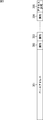
- FIG. 4 schematically shows a state in which the physical pages 207 are arranged on the RAM 102 (FIG. 1).
- the RAM 102 In the RAM 102, one page of physical pages 207 is arranged in order from the physical page 207-0 to the physical pages 207-n.
- one physical page 207 is often configured to be managed as one page in units of 4 KB to 64 KB in this way.
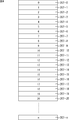
- FIG. 5 is a diagram for explaining a usage state of a physical page when the software is in a predetermined operation state.
- pages in which numbers are described are used pages, and pages in which numbers are not described indicate pages that are not used.
- the program code and data used by the software may be used as shown in FIG. 5 when the software state is viewed in a certain unit time even if all areas are used. Many. That is, there are pages that are used and pages that are not used, and not all pages are used.
- the recovery operation starts after the sequential reading from the physical page 207-0 to the physical page 207-n is performed. It is set to the operating state.
- the software in order for the software to be in a predetermined operation state, it is only necessary to read a plurality of predetermined physical pages 207 as shown in FIG. Therefore, in the present invention, by controlling reading as described later, only the required physical page 207 is read as shown in FIG.
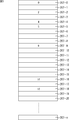
- FIG. 6 is a diagram showing a physical memory map of software. Note that the processing described below depends on the CPU 101 and the OS, and as long as these functions are implemented, there is no limitation on the configuration and memory arrangement, and the present invention is applied only to the following description. It is not shown.
- the nonvolatile memory 104 is a memory that retains stored contents even when the power is turned off.
- a FLASH ROM is imagined as the nonvolatile memory 104.
- the nonvolatile memory 104 is mapped on the main memory, but the contents are retained even when the power is turned off, and the nonvolatile memory 104 has a capacity larger than that of the RAM 102.
- the nonvolatile memory 104 to which the present invention can be applied does not necessarily have to be mapped on a memory map, such as access via I / O, and there is no limitation on its architecture.
- Data 401 is a readable / writable data area used by the program code 402.
- the data 401 is stored as a physical page 207 divided into a specific size. Since the data 401 needs to be readable and writable, it is preferably placed on the RAM 102.
- the program code 402 indicates a desired program to be activated / executed.
- an OS such as Windows (registered trademark) or Linux
- the program includes the OS and the software.
- the program code 402 is divided as a physical page 207 and stored. This program code 402 is placed on the RAM 102 or the ROM 103.
- the MMU table 403 indicates the level 1 descriptor table 201 and the level 2 descriptor table 204 shown in FIG.
- the page fault handler 404 is an access-prohibited attribute of the level 2 descriptor 206 of the MMU 131, and is a program for performing exception processing via an interrupt vector when a page fault occurs.
- the page fault handler 404 is described separately from the program code 402, but it may be included in the program code 402.
- the interrupt vector 405 is an interrupt vector possessed by a general CPU.
- the program code jumps to the page fault in this interrupt vector, and as a result, the page fault handler 404 is called.
- the physical addresses for the logical addresses of the data 401, the program code 402, the MMU table 403, and the interrupt vector 405 can be mapped to arbitrary addresses.
- the image storage program 406 is a program for storing a memory image in the nonvolatile memory 104 in a desired state after a desired program is started.
- the logical address and physical address of the image storage program 406 need to be mapped to the same address.
- the image restoration program 407 reads the physical memory image saved by the processing of the image saving program 406 in units of physical pages as necessary, and reads the data 401 and the program code 402 from the nonvolatile memory 104 into the corresponding physical page. It is a program for returning.
- the logical address and physical address of the image restoration program 407 need to be mapped to the same address.
- the boot loader 408 is a boot loader that is activated first after power-on or reset.
- the boot loader 408 mainly initializes the minimum I / O necessary for starting.
- the software has such a configuration.
- the software includes an OS and the like.
- predetermined software is operated on hardware including a RAM having a capacity of 4 GB. It is assumed that the total capacity of the predetermined software program and data is 4 GB.
- the software has various modes and functions, and it is very unlikely that the full capacity of 4 GB is used only by a predetermined single function.
- the software waits for key input from the user in a specific state after startup.
- the boot loader is activated, and this software is started up and waits for a key input from the user.
- this software is activated at high speed by applying hibernation, which is a known technology, the CPU and I / O registers are stored in a state waiting for key input from the user in preparation for creating a memory image.
- a total of 4 GB of code and data is stored in some nonvolatile memory.
- the reverse is true, the normal startup process does not pass, the 4 GB memory is expanded, the CPU and I / O registers are restored, and the process returns to the key input process.
- (A) The OS or desired software is activated in the normal activation mode, and the software is in a desired state.
- the image storage program is activated, and all page tables of the MMU 131 are activated by the activated image storage program. After the predetermined information is rewritten to the information indicating the access prohibition, the memory image in the state (A) is stored in the register and the process is terminated.
- (C) After the next time , It is started in the desired state of (A) by entering the fast startup mode
- MMU 131 Memory Management Unit of the CPU is used in the present embodiment.
- the OS may use the MMU 131, but before the OS uses, the software to which the present invention is applied is restored, and the OS knows that the software to which the present invention is applied has operated the MMU 131. do not do.
- the software to which the present invention is applied also has a function of giving a mark indicating that access to the page is prohibited.
- a page fault handler 404 for processing a page fault calculates a page from the address where the page fault occurs, and the software to which the present invention is applied checks the marked mark, and the page is read from the nonvolatile memory 104 to the main memory. (For example, the RAM 102), and the MMU 131 table is written back as it was before rewriting.
- A Normal startup
- the startup mode switching unit 110 is set to the normal startup mode, and the OS and a desired program are started by a normal method.
- A-2 After a desired program is started, the software is operated to bring the software into a desired state. It is started in this state at high speed startup.
- (B) Saving state (B-1)
- the image saving program 406 is activated by any key or command. There are no particular restrictions on the activation method for this activation.
- (B-2) The image storage program 406 stores the memory image and the register in a state where it is desired to start at high speed from the next time. Specifically, the image storage program 406 sets all the tables of the MMU 131 to the access prohibited state, and the data 401, the program code 402, the MMU table 403, the page fault handler 404, the interrupt vector 405, and the register at that time Are stored in the nonvolatile memory 104.
- C Fast startup
- the startup mode switching unit 110 is set to the fast startup mode.
- the boot loader 408 determines the start mode, and when it is in the high speed start mode, calls the image restoration program 407.
- the image restoration program 407 restores the MMU table 403, page fault handler 404, and interrupt vector 405 saved by the image saving program 406.
- C-2 Return to the address after the image storage program 406 is activated in the process of B-1, that is, jump. Since all the MMUs 131 are set to the access prohibited state, a page fault occurs at the corresponding address each time the program code 402 or data 401 is accessed, and the page fault handler 404 is called.
- the page fault handler 404 reads one page of the corresponding physical page 207 from the nonvolatile memory 104 and restores the MMU 131 to its original state.
- C-4 Necessary page faults continue to occur until page faults occur one after another and the state becomes A-2.
- C-5) The physical page 207 is read until the state A-2 is reached.
- the physical page 207 read in this process depends on the software to be executed and its state, but is very small. Compared to reading all the physical pages 207 as in the conventional hibernation technique. Thus, the startup time can be significantly shortened.
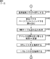
- step S101 the hard disk recorder 100 (FIG. 1) is powered on or reset to start the system.
- step S102 the boot loader 408 (FIG. 6) is activated.
- the boot loader 408 activated in step S102 initializes the minimum hardware for operating the OS and desired software, and transfers software stored in the ROM 103 and HDD 108 to the RAM 102 as necessary. Any boot loader that can execute such processing is assumed.
- the boot loader 408 depends on the system and is not essential. Therefore, depending on the system, step S102 may be omitted.
- step S103 the state of the start mode switching unit 110 is checked, and the transition between the normal start mode and the high speed start mode is switched (it is determined whether or not the normal start switch is ON).
- step S104 the process proceeds to step S161 (FIG. 9).
- step S103 If it is determined in step S103 that the normal activation switch is ON, the normal activation flag is set to ON in order to activate in the normal activation mode.
- the process proceeds to step S105, and the OS is activated if the system is equipped with the OS.
- the MMU 131 In the case of a general system, the MMU 131 is initialized when the OS is started, and the table of the MMU 131 in FIG. 2 is created. In the present invention, the installation of the OS is not essential, but the MMU 131 needs to be initialized if the system does not include the OS. Further, even if the OS is installed, there is no limitation on the type of OS.
- step S106 desired software to be started at high speed is started.
- step S107 the activated software operates.
- This process corresponds to the process A-2 described above.
- the software transitions to the same state that was started by fast startup. For example, assuming that there are a plurality of modes in the desired software, and if it is desired to start at a high speed in a specific mode, the software is operated and the mode is changed to that mode. For example, in the case of the hard disk recorder 100, there are a reservation mode, a playback mode, a setting mode, and the like, but when the user frequently uses the playback mode, the mode is changed to the playback mode.
- step S108 it is determined whether or not the processing of the image storage program 406 (FIG. 6) has been started.
- This process corresponds to the above-described process B-1. Processing by the image storage program 406 is started by a command, key operation, switch, or the like. There is no limitation on the execution means of the image storage program 406. If it is determined in step S108 that the processing of the image storage program 406 (FIG. 6) has not been started, the processing is returned to step S107, and the subsequent processing is repeated. That is, in this case, the software operation is continued.
- step S107 if it is determined in step S107 that the processing of the image storage program 406 (FIG. 6) has started, in other words, if it is determined that the operation of the software has ended, the processing proceeds to step S109.
- the following processes in steps S109 to S116 correspond to the above-described process B-2. Further, the processes in steps S109 to S116 are processes executed by the image storage program 406.
- step S109 the register of the I / O unit 109 shown in FIG. 1 is saved. Basically, the set value is acquired and saved. With respect to I / O, it is not always possible to read all registers, and in this case, it is necessary to deal with them individually. Note that the type and specification of I / O are arbitrary, and there are no particular restrictions on the application of the present invention.
- step S110 the CPU 101 register is saved. Basically, all registers of the CPU 101 are saved.
- the types of the CPU 101 and the register are arbitrary, and there are no particular restrictions on the application of the present invention.
- step S111 the address space is switched.
- the CPU 101 normally operates in the virtual address mode. This mode is changed from the virtual address mode to the physical address mode. Since the transition method from the virtual address mode to the physical address mode depends on the architecture of the MMU 131, the transition method for applying the present invention is not limited. Further, when the transition is made from the virtual address mode to the physical address mode, the address space changes. Therefore, in the processing in step S111, it is necessary to map the logical address and the physical address to the same address space.
- step S112 a cache flush is executed.
- TLB Translation Look-aside Buffer
- a primary cache a primary cache
- a secondary cache a secondary cache
- the cache flush process in step S112 is performed as necessary, and may be omitted in some cases.
- step S113 the MMU table 403 of the MMU 131 is rewritten with information that prohibits access to all physical pages 207.
- the MMU table rewriting process in step S113 will be described later with reference to the flowchart of FIG.
- step S113 when the MMU table 403 of the MMU 131 is rewritten, the process proceeds to step S114.
- step S114 a cache flush is executed. If the CPU 101 is equipped with a TLB, primary cache, and secondary cache and they are valid, the TLB and cache need to be flushed. This is to ensure that the contents of the MMU table 403 of the MMU 131 rewritten by the processing in the previous step S113 are reflected in the RAM 102.
- the cache flush process in step S114 is performed as necessary, and may be omitted in some cases.
- step S115 the entire contents of the RAM 102 are stored in the nonvolatile memory 104.
- the relative address position of the nonvolatile memory 104 with respect to the address of the RAM 102 needs to match. For example, it is assumed that the physical address of the RAM 102 is mapped from 0x10000000 to 0x1ffffff. In this case, for example, for the non-volatile memory 104, it is necessary to read data with addresses from 0x40000000 to 0x4ffffffff.
- the offset of the nonvolatile memory 104 with respect to the address of the RAM 102 is 0x30000000, even the address with respect to the RAM 102 can be converted into the address in the nonvolatile memory 104 only by adding the offset of 0x30000000.
- the nonvolatile memory 104 does not necessarily need to be mapped on the memory map. It suffices if reading can be performed using the address to which the offset is added as a key.
- the storage method for the nonvolatile memory 104 depends on the architecture, but the storage method is not limited in applying the present invention.
- step S116 the processing in the image storage program 406 is terminated.
- the power can be turned off or reset (RESET).
- step S113 there remains a detailed description of the processing when it is determined in step S103 that the normal activation switch is not ON and the MMU table rewriting processing in step S113.
- the MMU table rewriting process in step S113 will be described in detail with reference to the flowchart of FIG.
- the process based on the flowchart shown in FIG. 8 is a process in which the MMU table 403 of the MMU 131 has the configuration shown in FIG.
- step S131 when rewriting of the MMU table 403 of the MMU 131 is started, first, the head address of the level 1 descriptor table 201 is assigned to the variable level 1 descriptor pointer. In step S132, the level 1 descriptor 203 is acquired from the address pointed to by the variable level 1 descriptor pointer.
- step S133 it is determined whether or not a pointer to the level 2 descriptor table 204 exists in the level 1 descriptor 203 acquired in the process of step S132. If it is determined in step S133 that a pointer to the level 2 descriptor table 204 exists in the level 1 descriptor 203, the process proceeds to step S136, and a pointer to the level 2 descriptor table 204 exists in the level 1 descriptor 203. If it is determined not to proceed, the process proceeds to step S134.
- step S134 the variable level 1 descriptor pointer is moved to the address of the next level 1 descriptor pointer. Then, the process proceeds to step S135 to determine whether or not the level 1 descriptor pointer has finally reached.
- step S135 Until it is determined in step S135 that the level 1 descriptor pointer has finally reached, the process is returned to step S134, and the process in which the variable level 1 descriptor pointer is moved to the address of the next level 1 descriptor pointer is repeated. . If it is determined in step S135 that the level 1 descriptor pointer has finally reached, the process proceeds to step S114 (FIG. 7). That is, it is determined that the rewriting of the MMU table has been completed, and the processing is returned to the processing of the flowchart shown in FIG.
- step S133 if it is determined in step S133 that a pointer to the level 2 descriptor table 204 exists in the level 1 descriptor 203, the process proceeds to step S136.
- step S136 the head address of the level 2 descriptor table 204 is substituted for the variable level 2 descriptor pointer.
- step 137 the level 2 descriptor 206 is acquired from the address indicated by the variable level 2 descriptor pointer.
- step S138 it is determined whether or not the physical page 207 exists in the level 2 descriptor 206 acquired in the process of step S137. If it is determined in step S138 that the physical page 207 exists in the acquired level 2 descriptor 206, the process proceeds to step S139, and it is determined that there is no physical page 207 in the acquired level 2 descriptor 206. If YES, the process proceeds to step S143.
- step S139 it is determined whether or not the physical page 207 in the level 2 descriptor 206 acquired in step S137 is within the address range in the RAM 102 to be saved in step S115 (FIG. 7). Is done. If it is determined in step S139 that the physical page 207 in the level 2 descriptor 206 is within the address range in the RAM 102 to be stored, the process proceeds to step S140, and the process is advanced to the storage target RAM 102. If it is determined that it is not within the address range, the process proceeds to step S143.
- step S140 the access permission bit (access permission bit 305 in FIG. 3) of the level 2 descriptor 206 acquired in step S137 is checked to determine whether or not the physical page 207 is permitted to access. If it is determined in step S140 that access to the physical page 207 is permitted, the process proceeds to step S141. If it is determined that access to the physical page 207 is not permitted, the process proceeds to step S143. Is advanced.
- step S141 the access permission bit 305 of the level 2 descriptor 206 acquired in the process of step S137 is rewritten to a bit indicating access prohibition.
- step S142 marking is performed on the rewritten level 2 descriptor 206. In this process, whether the access permission bit 305 of the level 2 descriptor 206 acquired in the process of step S137 is rewritten by software to which the present invention is applied, or rewritten by the operation of other software, for example, the original OS or the like. This is done to store (mark) information for identifying whether the event has occurred.
- the marking method in step S142 depends on the architecture, and there is no restriction in applying the present invention. For example, if there is an empty bit that is not used in the level 2 descriptor 206, the empty bit can be used as a bit for embedding marking information. Further, a place where a table is separately provided and a place where marking is not performed may be managed. In any case, if the system is equipped with an OS or the like and the OS uses these bits, the present invention can be implemented by adopting a coexistence mechanism.
- step S143 the variable level 2 descriptor pointer is moved to the address of the pointer of the next level 2 descriptor 206.
- step S138 when it is determined in step S138 that the physical page 207 does not exist in the level 2 descriptor 206, or when it is determined in step S139 that the level 2 descriptor 206 does not point to the RAM 102. Alternatively, it comes when it is determined in step S140 that access to the physical page 207 is not permitted.
- step S144 it is determined whether or not the level 2 descriptor pointer has finally reached.
- step S144 the process returns to step S137 until it is determined that the level 2 descriptor pointer has finally reached, and the subsequent processes are repeated. On the other hand, if it is determined in step S144 that the level 2 descriptor pointer has finally reached, the process proceeds to step S134. Since the processing after step S134 has already been described, the description thereof is omitted.
- the fast startup is executed when it is determined in step S103 that the normal startup switch is not turned on, that is, when it is determined that the switch has been switched to the fast startup.
- the flowchart of FIG. 9 is a flowchart in which the process proceeds when it is determined in step S103 that the normal activation switch is not turned on, and is a flowchart for explaining the process at the time of high-speed activation.
- step S161 the normal start flag is set to OFF (the fast start flag is ON) in order to start in the high speed start mode.
- step S162 as necessary, the interrupt vector 405, the page fault handler 404, and the MMU table 403 are read into the same address of the RAM 102 as when the image was saved.
- step S163 the MMU table of the MMU 131 is read.
- the MMU table reading process executed in step S163 will be described later with reference to the flowchart of FIG.
- step S164 the address space of the CPU 101 is changed from the physical address mode to the virtual address mode.
- the address space changes. Therefore, in the processing in step S164, the logical address and the physical address are mapped to the same address space.
- step S165 the value of the register of the CPU 101 saved in step S110 (FIG. 7) is read from the nonvolatile memory 104 and returned to the CPU 101.
- the type of the CPU 101 and the register is arbitrary, and there is no limitation in applying the present invention.
- step S166 the I / O register value saved in step S109 (FIG. 7) is read from the nonvolatile memory 104 and returned to the I / O unit 109.
- the type and specification of I / O are arbitrary, and there are no restrictions on the application of the present invention.
- step S107 the software operates.
- the processing of steps S104 to S106 is not executed, and the software starts operation in step S107. Therefore, at least the time required for the software to start operating can be shortened by the amount of processing in steps S104 to S106.
- the time required for starting the OS and initializing the MMU in step S105 and the time required for starting the software in step S106 can be eliminated, a significant reduction in time can be expected.
- step S181 when reading of the MMU table 403 is started, the level 1 descriptor table 201 is first read.
- the contents of the RAM 102 are stored in the nonvolatile memory 104 in the process of step S115 (FIG. 7). From the contents stored in the nonvolatile memory 104, only the level 1 descriptor table 201 is stored. Read out.
- step S182 the leading address of the level 1 descriptor table 201 is assigned to the variable level 1 descriptor pointer.
- step S183 the level 1 descriptor 203 is acquired from the address indicated by the variable level 1 descriptor pointer.
- step S184 it is determined whether or not a pointer to the level 2 descriptor table 204 exists in the level 1 descriptor 203 acquired in the process of step S183.
- step 184 If it is determined in step 184 that a pointer to the level 2 descriptor table 204 exists in the acquired level 1 descriptor 203, the process proceeds to step S187, and the level 2 descriptor table is stored in the acquired level 1 descriptor 203. If it is determined that there is no pointer to 204, the process proceeds to step S185.
- step S185 the variable level 1 descriptor pointer is moved to the address of the next level 1 descriptor pointer. Then, in step S186, it is determined whether or not the level 1 descriptor pointer has finally reached. If it is determined in step S186 that the level 1 descriptor pointer has reached the end, the process proceeds to step S164 (FIG. 9). That is, in this case, since the reading of the MMU table 403 is completed, the process proceeds to the next process.
- step S186 determines whether the level 1 descriptor pointer 203 has been reached the final value. If it is determined in step S186 that the level 1 descriptor pointer 203 has not reached the final value, the processing is returned to step S183, and the subsequent processing is repeated. Steps S183 to S186 are repeated, and if it is determined in step S184 that a pointer to the level 2 descriptor table 204 exists in the acquired level 1 descriptor 203, the process proceeds to step S187.
- step S187 it is determined whether or not the pointer to the level 2 descriptor table 204 in the level 1 descriptor 203 acquired in step S183 points to the RAM 102. If it is determined in step S187 that the pointer to the level 2 descriptor table 204 points to the RAM 102, the process proceeds to step S188, and it is determined that the pointer to the level 2 descriptor table 204 does not point to the RAM 102. If so, the process proceeds to step S185, and the subsequent processes are repeated.
- step S188 the level 2 descriptor table is read.
- the level 2 descriptor table 204 is stored as the contents of the RAM 102 in the nonvolatile memory 104 in the process of step S115 (FIG. 7), and only the level 2 descriptor table 204 is read from the contents stored in the nonvolatile memory 104. . Thereafter, the process proceeds to step S185, and the subsequent processes are repeated.
- step S201 the process jumps to the interrupt vector 405. That is, a jump from the interrupt vector 405 to the interrupt handler that performs the actual page fault process is executed.
- the general CPU 101 jumps to a specific interrupt vector as an interrupt process and processes it as an interrupt handler.
- the flowchart relating to the processing when a page fault occurs shown in FIG. 11 assumes an interrupt handler that processes a page fault interrupt, but these depend on the architecture of the CPU 101.
- the application of the present invention is not limited by the manufacturer or model number of the CPU 101.
- step S202 it is determined whether or not the normal activation flag is ON.
- the normal activation flag is set to ON in the process of step S104 (FIG. 7).
- step S202 if it is determined that the normal activation flag is ON, in other words, if it is determined that the normal activation flag is normal, the process proceeds to step S207.
- step S203 if it is determined in step S202 that the normal activation flag is not ON, in other words, if it is determined that high-speed activation is performed, the process proceeds to step S203.
- step S203 it is determined whether the target physical page 207, that is, the physical page 207 corresponding to the address where the page fault has occurred is the marked physical page 207.
- the marking is a marking executed in the process of step S142 (FIG. 8). That is, the marked physical page 207 is a physical page 207 that has been rewritten to prohibit access by software to which the present invention is applied.
- Physical page address / page size (for example, 4KB in the above example) As shown in this equation, the physical page is obtained by dividing the address by the page size.
- step S203 if it is determined that the physical page 207 corresponding to the address where the page fault has occurred is a marked physical page 207, the process proceeds to step S204, and the physical page 207 is not marked. If it is determined, the process proceeds to step S207.
- step S204 the target physical page 207, that is, the physical page 207 corresponding to the address where the page fault has occurred is read out by 4 KB from the image stored in the nonvolatile memory 104 in the process of step S115 (FIG. 7).
- step S205 the access permission bit 305 of the level 2 descriptor 206 of the target physical page 207, that is, the physical page 207 corresponding to the address where the page fault has occurred is rewritten to access permission.
- step S206 the identification information marked in step S142 (FIG. 8) is canceled.
- step S207 standard page fault processing is executed. That is, during normal startup, or when software (such as an OS) other than the software to which the present invention is applied has been set to disallow access, normal startup or access disapproval processing is executed.
- step S207 depends on the system such as the OS and is not an essential process, and can be omitted in the present embodiment.
- Digital home appliances such as television receivers and hard disk recorders include models equipped with an OS (predetermined software).
- OS predetermined software
- the startup time may be long, but by applying the present invention, the startup time in these digital home appliances can be shortened.
- the battery life can be extended.
- a conventional method for realizing high-speed startup there has been a method of shifting a CPU or a memory to a power saving mode. In this method, although it is a power saving mode, power is required, and power consumption cannot be ignored for a battery-powered device.
- the present invention it is possible to save a startup image in a nonvolatile memory, and it is not necessary to use so-called suspend (corresponding to a conventional power saving mode) in which power is stopped while being supplied to a RAM. As a result, the battery life can be significantly extended.
- the start-up time can be shortened by applying the present invention, the start-up time can be started with a start time shorter than or equal to the start-up time required in the “fast start-up mode”. Therefore, it is not necessary to provide a “fast start-up mode”. Accordingly, it is possible to eliminate the state where the power must be constantly turned on in the “fast start-up mode”, and as a result, energy saving can be realized.
- the program executed by the computer described above may be a program that is processed in time series in the order described in this specification, or in parallel or at a necessary timing such as when a call is made. It may be a program for processing. It can also be configured with dedicated hardware. Further, in this specification, the system represents the entire apparatus constituted by a plurality of apparatuses.
Abstract
本発明は、起動時間を短縮することができるプログラム、制御方法、並びに制御装置に関する。 Memory Management Unit(MMU)を搭載したコンピュータシステム上で、MMUのテーブルに対し、ソフトウェアの動作に必要なページに対して、全てのページにてページフォルトが発生するようにページテーブルエントリが書き換えられる。起動時は、アクセスするRAMに対して発生したページフォルトに対し、保存したメモリイメージのページ単位の読み込みが実行される。このような読み込みが行われことで、不要なページの読み込みが行われず、その分の起動時間を短縮することが可能となる。本発明は、パーソナルコンピュータや組み込み型のコンピュータを備える電子機器に適用できる。
Description
本発明はプログラム、制御方法、並びに制御装置に関し、特に、ソフトウェアの起動を制御するときに好適なプログラム、制御方法、並びに制御装置に関する。
パーソナルコンピュータにおいて、OS(Operating System)を起動させ、所望のソフトウェアを動作させるまでには数分単位の起動時間が必要であった。これを高速に起動させる手法として、ハイバネーション(hibernation)と呼ばれる手法が存在する(例えば、特許文献1参照)。
特許文献1には、起動後のCPU(central processing unit)やI/O(input/output)レジスタ、RAM(Random Access Memory)イメージが、ハードディスクドライブ(HDD)やフラッシュメモリに格納されることが記載されている。そして、次に起動されるときに、格納されているRAMイメージが復帰され、その後、CPUやI/Oレジスタが再設定されることが記載されている。このように起動することで、OSの起動を高速化させることが、特許文献1では提案されている。このような提案に基づくハイバネーションと称される手法は、既にパーソナルコンピュータで適用されている。
また、組み込み型のコンピュータ、例えば、テレビジョン受像器、ハードディスクレコーダといった電子機器に組み込まれているコンピュータにおいても、ハイバネーションの手法が応用されている。
ハイバネーションを適用し、OSを起動させる場合とOSを通常通りに起動させる場合とを比較した場合、ハイバネーションを適用してOSを起動させる方が、より高速に起動させることができる。しかしながら、RAMの容量増加に伴って保存すべきRAMイメージのサイズも増加してしまい、起動時に、そのRAMイメージの展開時間も増加してしまう。結果として、RAMの大容量化に伴い高速起動が困難になってしまう。
また、パーソナルコンピュータは、CPUの性能も比較的高いため、仮にRAMイメージのサイズが増加してしまっても、そのRAMイメージを処理する性能が確保される。しかしながら、組み込み型のコンピュータの場合、CPUの性能が比較的低いものが使われることが多い。そのため、組み込み型のコンピュータの場合、RAMイメージが増加すれば、ハイバネーションの手法を適用しても、起動時の速度は低下してしまう。すなわち、組み込み型のコンピュータの場合、RAMイメージの増加による速度の低下は、より顕著に表れてしまう。
また、RAMイメージを圧縮することで、RAMイメージのサイズを小さくすることも提案されているが、起動時に伸張する処理が必要となる。この伸張処理にかかるCPUへの負荷や、伸張処理にかかる時間を考慮すると、起動の高速化という点では効果的な方法ではない。
このようなことを考慮し、特許文献2では、ハイバネーションのイメージの全ての転送を完了する前に、OSの実行を開始する手法が提案されている。しかしながら、この手法では、特別なハードウエアを搭載し、先行転送するページを予め特定しておく必要があるため、その特別なハードウエアの分だけコストが高くなるなどの問題点があった。
本発明は、このような状況に鑑みてなされたものであり、起動時間を短縮することができるようにするものである。
本発明の一側面のプログラムは、メモリを管理する機能を有する制御装置に、所定のソフトウェアの動作に必要なページに対して、全てのページでページフォルトが発生するようにページテーブルエントリを書き換え、前記ソフトウェアが起動時に、前記ページテーブルエントリで、ページフォルトが発生し、そのページフォルトが発生したページを順次読み出すステップを含む。
前記所定のソフトウェアが起動された後、前記ページテーブルエントリを書き換え、その起動時のデータ、プログラムコード、テーブル、ページフォルトハンドラ、割り込みベクタ、およびレジスタを、前記メモリに記憶させるようにすることができる。
前記メモリのうち、書き換えの対象となる前記ページテーブルエントリを記憶しているのはRAMであり、順次読み出される前記ページを記憶しているのは不揮発メモリであるようにすることができる。
組み込み型のコンピュータが読み込むようにすることができる。
本発明の一側面の制御方法は、メモリを管理する機能を有する制御装置の制御方法において、所定のソフトウェアの動作に必要なページに対して、全てのページでページフォルトが発生するようにページテーブルエントリを書き換え、前記ソフトウェアが起動時に、前記ページテーブルエントリで、ページフォルトが発生し、そのページフォルトが発生したページを順次読み出すステップを含む。
本発明の一側面の制御装置は、メモリを管理する機能を有する制御装置において、所定のソフトウェアの動作に必要なページに対して、全てのページでページフォルトが発生するようにページテーブルエントリを書き換える書き換え手段と、前記ソフトウェアが起動時に、前記ページテーブルエントリで、ページフォルトが発生し、そのページフォルトが発生したページを順次読み出す読み出し手段とを備える。
本発明の一側面のプログラム、制御方法、並びに制御装置は、所定のソフトウェアの動作に必要なページに対して、全てのページでページフォルトが発生するようにページテーブルエントリが書き換えられ、ソフトウェアが起動時に、ページテーブルエントリで、ページフォルトが発生し、そのページフォルトが発生したページが順次読みだされる。
本発明の一側面によれば、OSの起動時間を短縮することが可能となる。
以下に、本発明の実施の形態について図面を参照して説明する。
まず、本発明の概略を説明する。本発明は、Memory Management Unit(以下、MMUと略記する)を搭載したCPU(central processing unit)上で動作するOS(Operating System)やアプリケーション等のソフトウェアを高速に起動させるための手法である。
高速起動の対象となるソフトウェアが、一度、通常通りの方法で起動され、その状態のRAM(Random Access Memory)イメージが不揮発メモリ等に保存される。RAMイメージが、不揮発メモリ等に保存されるとき、MMUのテーブルが書き換えられ、全てのページでページフォルトが発生するように変更される。対象とされるソフトウェアには、ページフォルトハンドラが用意されており、ページフォルトが発生した場合、そのページフォルトが発生したページのみが、不揮発メモリからロードされる。
任意のソフトウェアが起動され、プログラムコードが実行されたり、そのソフトウェアが動作に必要なデータを読み出すために、RAMにアクセスしたりした場合、毎回ページフォルトが発生し、必要なページが不揮発メモリからRAMに逐次ロードされることになる。これにより、従来のハイバネーション起動とは異なり、全てのRAMイメージを不揮発メモリからメインRAMに予めロードする必要が無くなり、動作に必要な必要最小限のRAMイメージのみをロードすることが可能になる。よって、高速に所望のソフトウェアを起動・動作させることが可能となる。
本発明を使用することで、従来は数十秒~数分を要していたOSやソフトウエア(以下、単にソフトウェアとする)の起動時間を数秒程度に短縮することが可能となることが、本出願人により確認されている。以下に、具体的に説明する。
[情報処理装置の構成について]
図1は、本発明を適用した情報処理装置の一実施の形態の構成を示す図である。本発明を適用した情報処理装置は、パーソナルコンピュータ(PC)に適用できることは勿論のこと、組み込み型のコンピュータを有する装置にも適用できる。組み込み型のコンピュータを含む装置としては、テレビジョン受像器、ハードディスクレコーダといった電子機器がある。ここでは、ハードディスクレコーダに対して本発明を適用したときを例にあげて説明する。
図1は、本発明を適用した情報処理装置の一実施の形態の構成を示す図である。本発明を適用した情報処理装置は、パーソナルコンピュータ(PC)に適用できることは勿論のこと、組み込み型のコンピュータを有する装置にも適用できる。組み込み型のコンピュータを含む装置としては、テレビジョン受像器、ハードディスクレコーダといった電子機器がある。ここでは、ハードディスクレコーダに対して本発明を適用したときを例にあげて説明する。
図1は、本発明を適用した情報処理装置としてのハードディスクレコーダの構成を示す図である。図に示したハードディスクレコーダ100は、CPU101、RAM102、ROM(Read Only Memory)103、不揮発メモリ104、MPEG(Moving Picture Experts Group)エンコード・デコード部105、チューナ106、HDDインターフェース107、HDD108、I/O部109、起動モード切替部110を備える。
CPU101は、ハードディスクレコーダ100の各部を制御する。このCPU101は、Memory Management Unit(以下、MMUと記述する)を搭載し、RAM102を小分割して小単位(ページ)で管理できる仕組みを有している。なお、ここでは、MMU131がCPU101に含まれるとして説明を続けるが、MMU131が、CPU101に含まれず、外部に備えられている構成とすることも可能である。また、MMU131の形式には特に制限はないが、ページ単位にアクセスの許可・禁止の属性が設定可能で、アクセス禁止のページにアクセスした場合は、ページフォルトの例外が発生できる構成とされている。また、CPU101のMMU131は、4キロバイト(以下、4KBと記述する)を1ページとして管理するとして説明を続ける。
RAM102は、SRAM(Static Random Access Memory)やDRAM(Dynamic Random Access Memory)などで構成することが可能である。RAM102は、CPU101が使用する主記憶装置として機能し、そのような機能を有していれば、RAM102として用いることが可能である。
ROM103は、FLASH ROMやMask ROMなどの読み込み専用のメモリである。ROM103は、OSやアプリケーションソフトウェアが格納され、そのような格納が行えれば、どのような種類のROMが用いられても本発明においては良い。
不揮発メモリ104は、ハードディスクレコーダ100の電源が切られても、記憶している内容が保持されるメモリである。例えば、FLASH ROMや、バックアップ機能付きのSRAM、DRAMなどで構成することが可能である。
不揮発メモリ104には、後述するソフトウェアが起動した後に、RAM102に格納されたソフトウェアのメモリイメージが格納される。そのため、不揮発メモリ104の容量は、RAM102の容量以上の容量とされることが好ましい。ただし、データ圧縮等によりデータを縮小するようにした場合、不揮発メモリ104の容量は、RAM102の容量以下の容量でも良い。また、不揮発メモリ104は、HDD108と兼用することも可能である(HDD108を不揮発メモリ108として利用することも可能である)。
MPEGエンコード・デコード部105は、動画の圧縮・伸張を行う。動画は、チューナ106を介して供給される。チューナ106は、ユーザの指示に基づき、複数の番組(動画)から、1つの動画を選択し、MPEGエンコード・デコード部105に供給する。MPEGエンコード・デコード部105は、必要に応じ、HDDインターフェース107を介して、HDD108にチューナ106からのデータを供給したり、HDD108からのデータをHDDインターフェース107を介して、受信したりする。また、その際、必要に応じ、エンコードまたはデコードの処理を実行する。
I/O部109は、起動モード切替部110の状態をCPU101が読みとるために設けられている。以下に説明するソフトウェアは、高速起動イメージを取得するための通常起動モードと、高速起動イメージが取得された後の起動モードとしての高速起動モードを有する。I/O109と起動モード切替部110は、これらの起動モードの切り替えに用いられる。通常起動モードと高速起動モードの切り換えのために、起動モード切替部110をスイッチで構成することが可能である。また、通常起動モードと高速起動モードの切り換えのために、起動モード切替部110を、ブートローダ等からコマンドで切り替える構成とすることも可能である。
また、一度高速起動のイメージが作成されれば、通常起動モードを不要とすることができるため、高速起動モードのみが実装され、通常起動モードと高速起動モードの切り換えを不要とする構成としても良い。そのような構成とした場合、I/O部109と起動モード切替部110を省略した構成とすることも可能である。
[MMUについて]
図2は、CPU101が装備するMMU131のモデルを示す図である。図2に示したMMU131は、32bitクラス以上のCPU101が装備するモデルである。MMU131の構成や、物理アドレス、仮想アドレス、各テーブルのインデックスに使用するbit数、テーブルの段数等は、CPU101のメーカに依存するものであるが、特にメーカのアーキテクチャに依存はしない。ここでは説明の都合上、32bit等の具体的な数字を例にあげて説明するが、その数値は、本発明の適用範囲の限定を示すものではない。
図2は、CPU101が装備するMMU131のモデルを示す図である。図2に示したMMU131は、32bitクラス以上のCPU101が装備するモデルである。MMU131の構成や、物理アドレス、仮想アドレス、各テーブルのインデックスに使用するbit数、テーブルの段数等は、CPU101のメーカに依存するものであるが、特にメーカのアーキテクチャに依存はしない。ここでは説明の都合上、32bit等の具体的な数字を例にあげて説明するが、その数値は、本発明の適用範囲の限定を示すものではない。
MMU131は、最終的な物理ページを指し示すテーブル内エントリの属性にアクセス許可もしくはアクセス許可相当の機能を実装し、不許可の場合にアクセスしたときには、ページフォルトもしくはページフォルト相当の例外処理が発生できる機能を少なくとも有する。
MMUレジスタ200は、MMU131に装備されるレジスタである。このレジスタにレベル1ディスクリプタテーブル201の先頭アドレスが代入される。レベル1ディスクリプタテーブル201は、メモリ上に置かれたレベル1メモリテーブルである。物理アドレス空間が32bitの場合、1つのアドレスを指し示すのに32bit、即ち4バイトが使用されるため、レベル1ディスクリプタテーブル201のサイズは、12bit空間=4KB空間×4バイトで16KBのサイズとなる。
仮想アドレス202は、レベル1メモリテーブルのインデックスとして使われる仮想アドレスの31bitから20bitを示す。VAはVirtual Address(仮想アドレス)を意味する。所定の仮想アドレスにアクセスがあった場合、レベル1ディスクリプタテーブル201の先頭アドレスから仮想アドレスの31bitから20bitがインデックスとされ、レベル1ディスクリプタ203にアクセスがされる。
物理アドレス空間が32bitのCPU101である場合、1つのアドレスを示すのに32bit、即ち4バイトが使用されるため、レベル1ディスクディスクリプタのアドレスは以下のような式になる。
レベル1ディスクリプタ203のアドレス
= レベル1ディスクリプタテーブル201の先頭アドレス
+ 仮想アドレス202(VA[31:20]) ×4
レベル1ディスクリプタ203のアドレス
= レベル1ディスクリプタテーブル201の先頭アドレス
+ 仮想アドレス202(VA[31:20]) ×4
レベル1ディスクリプタ203は、レベル2ディスクリプタテーブル204の先頭アドレスを指し示すポインタや属性から構成されるディスクリプタである。レベル2ディスクリプタテーブル204の先頭アドレスから仮想アドレスの19bitから12bitがインデックスとされ、レベル2ディスクリプタ206にアクセスされる。
物理アドレス空間が32bitのCPU101である場合、1つのアドレスを示すのに32bit、即ち4バイトが使用されるため、レベル2ディスクディスクリプタのアドレスは以下のような式になる。
レベル2ディスクリプタ206のアドレス
= レベル2ディスクリプタテーブル204の先頭アドレス
+ 仮想アドレス205(VA[19:12]) ×4
レベル2ディスクリプタ206のアドレス
= レベル2ディスクリプタテーブル204の先頭アドレス
+ 仮想アドレス205(VA[19:12]) ×4
レベル2ディスクリプタ206は、4KBの物理ページ207を示すポインタや属性から構成されるディスクリプタである。物理ページ207は、最終的に仮想アドレスから物理アドレスに変換された1ページの物理メモリである。物理ページ207の4KB内のアドレスは、仮想アドレス208(VA[11:0])で指定される。
図3は、レベル1ディスクリプタ203やレベル2ディスクリプタ206の一例である。図3におけるディスクリプタはあくまでも一例であり、本発明は、このような一例で示した特定のCPU101やアーキテクチャに依存することを示すものではない。
ベースアドレス301は、次のテーブルや物理ページの先頭アドレスを指すポインタである。属性302乃至304は、それぞれ、実行可・不可、特権モード・ユーザモードといった属性を示す属性bitである。アクセス許可bit305は、このディスクリプタが示す物理ページに対してのアクセスが許可されているか否かを示すbitである。このアクセス許可bit305で、アクセスを禁止するように設定されている物理ページにアクセスがあった場合、一般的には、ページフォルトと呼ばれる例外処理、即ち割込み処理が実行され、そのような機構が必要である。よって、CPU101のアーキテクチャに依存はしないが、ページフォルト、もしくはページフォルト相当の機能は、CPU101に装備されている必要がある。
[物理ページについて]
図4は、物理ページ207が、RAM102(図1)上に並んでいる状態を擬似的に示している。RAM102には、1ページ分の物理ページ207が、物理ページ207-0から順に、物理ページ207-nまで配列されている。MMU131搭載のCPU101上でソフトウェアが動作される場合、1ページの物理ページ207は、このように4KB乃至64KB単位で1ページとして管理されるように構成されていることが多い。
図4は、物理ページ207が、RAM102(図1)上に並んでいる状態を擬似的に示している。RAM102には、1ページ分の物理ページ207が、物理ページ207-0から順に、物理ページ207-nまで配列されている。MMU131搭載のCPU101上でソフトウェアが動作される場合、1ページの物理ページ207は、このように4KB乃至64KB単位で1ページとして管理されるように構成されていることが多い。
図5は、ソフトウェアが所定の動作状態であるときの物理ページの使用状況について説明するための図である。図5中、数字が記載されているページが使用されているページであり、数字が記載されていないページは使用されていないページを示す。ソフトウェアが使うプログラムコードやデータが、図4に示したように、全ての領域を使っていたとしても、ソフトウェアの状態をある単位時間でみた場合、図5で示すように使われていることが多い。すなわち、使用されているページと使用されていないページとがあり、全てのページが使用されているわけではない。
このソフトウェアが、所定の動作状態のときには、物理ページ207-0、物理ページ207-2、物理ページ207-4、物理ページ207-5、物理ページ207-9、物理ページ207-16、および物理ページ207-18が使用される。すなわち、図4に示したように、RAM102には、1ページ分の物理ページ207が、物理ページ207-0から順に、物理ページ207-nまで配列されているが、そのうち所定のソフトウェアが、所定の動作状態のときには、全てのページが使われるわけではなく、図5に示したように、複数のページのみが使用される。
従来のハイバネーション起動による起動の場合、ソフトウェアが動作する前に、図4に示したように、物理ページ207-0から物理ページ207-nまで、順次読み出しが行われてから復帰動作が始まり、所定の動作状態にされる。しかしながら実際に、そのソフトウェアが所定の動作状態になるためには、図5に示したように、所定の複数の物理ページ207が読み出されるだけでよい。そこで、本発明においては、後述するように読み出しを制御することで、図5に示したように、必要とされる物理ページ207のみが読み出されるようにする。
従来のハイバネーション起動による起動の場合、図4に示したように物理ページ207-0から順次読み出しが行われるため、換言すれば、必要のない物理ページ207も読み出されるため、読み出しに時間がかかり、結果として、所定のソフトウェア(OSなども含む)の起動が遅くなるということがあった。しかしながら、本発明によれば、図5に示したように、必要とされる物理ページ207のみが読み出されるため、読み出しにかかる時間を短縮することができ、所定のソフトウェア(OSなども含む)の起動を早くすることが可能となる。
図6は、ソフトウェアの物理メモリマップを示す図である。なお、以下に説明する処理は、CPU101やOSに依存するもので、これらの機能が実装されていれば構成やメモリ配置に制限はなく、以下の説明だけに、本発明が適用されることを示すものではない。
不揮発メモリ104は、電源を切っても記憶内容が保持されるメモリである。図6に示した例では、不揮発メモリ104としてFLASH ROMをイメージしている。不揮発メモリ104は、メインメモリ上にマッピングされているが、電源を切っても内容が保持され、且つ、RAM102以上の容量を装備している。しかしながら、本発明を適用できる不揮発メモリ104は、I/O経由でのアクセス等、必ずしもメモリマップ上にマッピングされている必要はなく、そのアーキテクチャに制限はない。
データ401は、プログラムコード402が使用する読み書きができるデータ領域である。データ401は物理ページ207として、ある特定の大きさに分割されて格納される。データ401は、読み書きできる必要があるのでRAM102上に置かれることが好ましい。
プログラムコード402は、起動・実行させる所望のプログラムを示す。一般的なパーソナルコンピュータでWindows(登録商標)やLinuxと言ったOSが搭載され、その上で動作するソフトウェアである場合、プログラムとは、そのOSとソフトウェアを含む。プログラムコード402は、物理ページ207として、ある特定の大きさに分割されて格納される。このプログラムコード402は、RAM102またはROM103上に置かれる。
MMUテーブル403は、図2に示したレベル1ディスクリプタテーブル201およびレベル2ディスクリプタテーブル204を示している。ページフォルトハンドラ404は、MMU131のレベル2ディスクリプタ206がアクセス禁止の属性であり、ページフォルトが発生したとき、割込ベクタ経由で例外処理を行うためのプログラムである。ここではプログラムコード402と分けて、ページフォルトハンドラ404を記述しているが、プログラムコード402に含まれる場合もある。
割込ベクタ405は、一般的なCPUが持つ割込ベクタである。ページフォルトが発生した場合、この割込ベクタ内のページフォルトにプログラムコードがジャンプし、結果的にページフォルトハンドラ404が呼び出される。
データ401、プログラムコード402、MMUテーブル403、および割込ベクタ405の論理アドレスに対する物理アドレスは、任意のアドレスにマッピングできる。
イメージ保存プログラム406は、所望のプログラムが起動された後、所望の状態でメモリイメージが不揮発メモリ104に保存されるようにするためのプログラムである。イメージ保存プログラム406の論理アドレスと物理アドレスは、同一アドレスにマッピングされる必要がある。
イメージ復帰プログラム407は、イメージ保存プログラム406の処理により保存された物理メモリイメージを、必要に応じて物理ページ単位に、データ401やプログラムコード402を、対応する物理ページに、不揮発メモリ104から読み込み、復帰させるためのプログラムである。イメージ復帰プログラム407の論理アドレスと物理アドレスは、同一アドレスにマッピングされる必要がある。
ブートローダ408は、電源投入もしくはリセット後に最初に起動されるブートローダである。主にブートローダ408は、起動に必要な最低限のI/Oの初期化を行う。このような構成をソフトウェアは有する。
[ソフトウェアの動作について]
次に、本発明を適用したソフトウェアの動作について説明する。まず、概要を説明し、その後詳細を説明する。本発明によれば、ソフトウェアの局所性を利用し、ソフトウェアを高速に起動することができる。ソフトウェアにはOS等も含まれる。例えば、容量4GBのRAMを備えるハードウエア上で、所定のソフトウェアを動作させると仮定する。その所定のソフトウェアのプログラムおよびデータの容量の合計が、仮に4GBであったとする。一般的にソフトウェアは、様々なモードや機能を有し、所定の単一の機能だけで、全容量の4GBを使う可能性は極めて低い。
次に、本発明を適用したソフトウェアの動作について説明する。まず、概要を説明し、その後詳細を説明する。本発明によれば、ソフトウェアの局所性を利用し、ソフトウェアを高速に起動することができる。ソフトウェアにはOS等も含まれる。例えば、容量4GBのRAMを備えるハードウエア上で、所定のソフトウェアを動作させると仮定する。その所定のソフトウェアのプログラムおよびデータの容量の合計が、仮に4GBであったとする。一般的にソフトウェアは、様々なモードや機能を有し、所定の単一の機能だけで、全容量の4GBを使う可能性は極めて低い。
例えばソフトウェアが、起動後、特定の状態でユーザからのキー入力を待つとする。一般的にはハードウエアのリセット後、ブートローダが起動され、このソフトウェアが立ち上がってユーザからのキー入力待ちの状態とされる。このソフトウェアを既知の技術であるハイバネーションを適用して高速に起動させた場合、メモリイメージを作成する準備として、ユーザからのキー入力待ちの状態でCPUや各I/Oのレジスタが保存され、プログラムコードやデータの合計4GBが、何らかの不揮発メモリに格納されることになる。起動時はこの逆で、通常の起動プロセスは通らず、4GBのメモリが展開され、CPUやI/Oのレジスタが復帰され、キー入力の処理に戻ることになる。
上記ソフトウェアにおいて、「ユーザからの入力を待つ」という状態を考える。この状態では、キー入力の処理が繰り返されており、このようなキー入力に係わる処理に係わるプログラムコードやデータは比較的小さい。本発明は、この原理を利用して高速起動を実現する。動作は大きく分けると以下のようになる。
(A) 通常起動モードでOSや所望のソフトウェアが起動され、そのソフトウェアが所望の状態にされる
(B) イメージ保存プログラムが起動され、その起動されたイメージ保存プログラムにより、MMU131の全てのページテーブルに対してのアクセスを禁止するために、アクセス禁止を示す情報に所定の情報が書き換えられた後、上記(A)の状態のメモリイメージがレジスタに保存されて終了される
(C) 次回以降は、高速起動モードにされることで、(A)の所望の状態で起動される
(B) イメージ保存プログラムが起動され、その起動されたイメージ保存プログラムにより、MMU131の全てのページテーブルに対してのアクセスを禁止するために、アクセス禁止を示す情報に所定の情報が書き換えられた後、上記(A)の状態のメモリイメージがレジスタに保存されて終了される
(C) 次回以降は、高速起動モードにされることで、(A)の所望の状態で起動される
このような高速起動を実現するにあたり、基本的な準備として、通常通りにソフトウェアが起動され、そのソフトウェアが所望の状態にされ、その後、メモリイメージやレジスタが保存される。高速起動時は、ハイバネーション起動とは異なり、全てのメモリイメージがメインメモリに展開されるのではなく、実際に使われるメモリ、即ちプログラムコードやデータが、必要に応じて一部分のみ小刻みに展開される。
小刻みにプログラムコードやメモリが、メインメモリに展開される方法として、本実施の形態としてはCPUが持つMemory Management Unit(MMU131)が利用される例をあげて説明している。OSが、MMU131を使用する場合もあるが、OSが利用する前に、本発明が適用されたソフトウェアが元に戻し、OSは、本発明が適用されたソフトウェアがMMU131を操作したことには関知しない。
具体的には、メモリイメージが保存される前に、MMU131のテーブルの内容が書き換えられ、全てのページがアクセス禁止に設定される。また、本発明が適用されたソフトウェアは、前記ページをアクセス禁止にしたというマークを付与する機能も有する。
仮に、所望のソフトウェアがOS上で動作し、そのOSがMMU131を使用する場合も同じである。高速起動時は、MMU131のテーブルおよびCPUのレジスタのみ先行で復帰される。そして、メモリイメージが作成された後のアドレスに戻される。MMU131のテーブルは、全てアクセス禁止に設定されているので、戻りアドレスにジャンプした時にページフォルトが発生する。データアクセス時も同じである。ページフォルトを処理するページフォルトハンドラ404は、ページフォルトが発生したアドレスからページを計算し、且つ、本発明が適用されたソフトウェアが、マークしたマークをチェックし、そのページを不揮発メモリ104からメインメモリ(例えば、RAM102)へ読み込み、MMU131のテーブルを書き換え前の元の通りに書き戻す。
このような処理が繰り返されることで、大容量のメモリイメージであっても、所望の状態に復帰させるには最低限のメモリイメージの読み込みだけで済み、高速に起動することが可能となる。
[動作の詳細について]
上記してきたように、本発明によれば、所望のソフトウェアをある状態まで通常の起動と比較して高速に起動することが可能である。その高速起動を行う手順を大きく分けると、簡便に上記したが、(A)、(B)、(C)の3つに分類される。さらに(A)、(B)、(C)を、フローチャートを参照した説明の前に、さらに説明を加える。(A)、(B)の一連の流れは、一度実行されれば、毎回行う必要がない処理である。通常、(C)から実行されるようにすることで、高速起動することが可能となる。
上記してきたように、本発明によれば、所望のソフトウェアをある状態まで通常の起動と比較して高速に起動することが可能である。その高速起動を行う手順を大きく分けると、簡便に上記したが、(A)、(B)、(C)の3つに分類される。さらに(A)、(B)、(C)を、フローチャートを参照した説明の前に、さらに説明を加える。(A)、(B)の一連の流れは、一度実行されれば、毎回行う必要がない処理である。通常、(C)から実行されるようにすることで、高速起動することが可能となる。
(A)通常起動
(A-1) 起動モード切替部110を通常起動モードに設定し、通常の方法により、OSや所望のプログラムが起動される。
(A-2) 所望のプログラムが起動された後、ソフトウェアが操作されて、ソフトウェアが所望の状態にされる。高速起動時は、この状態で起動される。
(A-1) 起動モード切替部110を通常起動モードに設定し、通常の方法により、OSや所望のプログラムが起動される。
(A-2) 所望のプログラムが起動された後、ソフトウェアが操作されて、ソフトウェアが所望の状態にされる。高速起動時は、この状態で起動される。
(B)状態の保存
(B-1) 何らかのキーやコマンドなどによりイメージ保存プログラム406が起動される。この起動に関する起動方法には、特に制限はない。
(B-2) イメージ保存プログラム406は、次回以降に高速に起動したい状態で、メモリイメージとレジスタを保存する。具体的には、イメージ保存プログラム406は、MMU131のテーブルを全てアクセス禁止状態に設定し、その時点でのデータ401、プログラムコード402、MMUテーブル403、ページフォルトハンドラ404、割込ベクタ405、およびレジスタ類を不揮発メモリ104に保存させる。
(B-1) 何らかのキーやコマンドなどによりイメージ保存プログラム406が起動される。この起動に関する起動方法には、特に制限はない。
(B-2) イメージ保存プログラム406は、次回以降に高速に起動したい状態で、メモリイメージとレジスタを保存する。具体的には、イメージ保存プログラム406は、MMU131のテーブルを全てアクセス禁止状態に設定し、その時点でのデータ401、プログラムコード402、MMUテーブル403、ページフォルトハンドラ404、割込ベクタ405、およびレジスタ類を不揮発メモリ104に保存させる。
(C)高速起動
(C-1) 起動モード切替部110が、高速起動モードに設定される。ブートローダ408が、起動モードを判断し、高速起動モードの場合は、イメージ復帰プログラム407を呼び出す。イメージ復帰プログラム407は、イメージ保存プログラム406が保存したMMUテーブル403、ページフォルトハンドラ404、割込ベクタ405を復帰させる。
(C-2) B-1の処理でイメージ保存プログラム406が起動された後のアドレスに戻る、即ちジャンプする。MMU131が全てアクセス禁止状態に設定されているので、プログラムコード402やデータ401にアクセスされる毎に、対応するアドレスにてページフォルトが発生し、ページフォルトハンドラ404が呼ばれる。
(C-3) ページフォルトハンドラ404は、対応する物理ページ207を不揮発メモリ104から1ページ分読み出し、MMU131を元に戻す。
(C-4) ページフォルトが次々に発生し、A-2の状態になるまで、必要なページフォルトが発生し続ける。
(C-5) A-2の状態になるまで物理ページ207が読み込まれる。この処理で読み込まれる物理ページ207は、実行されるソフトウェアや、その状態にも依存するが、極めて少なく、従来のハイバネーション技術で行われていたように、全ての物理ページ207を読み込むのと比較して起動時間は著しく短くすることが可能となる。
図7乃至11のフローチャートを参照し、上記(A)、(B)、(C)の各動作についてさらに説明を加える。
図7のフローチャートは、上記(A)、(B)の処理に該当する。すなわち、主に、電源投入からイメージ保存までの処理に係わるフローチャートである。ステップS101において、ハードディスクレコーダ100(図1)の電源が投入、もしくはリセットが発生してシステムが起動される。
ステップS102において、ブートローダ408(図6)が起動される。このステップS102で起動されるブートローダ408は、OSや所望のソフトウェアを動作させるために最低限のハードウエアの初期化や、必要に応じてROM103やHDD108に格納されているソフトウェアをRAM102に転送させたりする処理を想定し、そのような処理を実行できるブートローダであればよい。ブートローダ408は、システムに依存するものであり必須のものではない。よって、システムによっては、このステップS102が省略される場合もある。
ステップS103において、起動モード切替部110の状態がチェックされ、通常起動モードか、高速起動モードかの遷移が切り替えられる(通常起動スイッチがONであるか否かが判断される)。起動モード切替部110が通常起動モードの場合、ステップS104に処理が進められ、高速起動モードの場合、ステップS161(図9)に進められる。
ステップS103において、通常起動スイッチがONであると判断されると、通常起動モードで起動するため、通常起動フラグがONに設定される。通常起動フラグがONに設定されると、ステップS105に処理が進められ、OSが搭載されているシステムであれば、OSが起動される。一般的なシステムの場合、OSが起動される時にMMU131が初期化され、図2のMMU131のテーブルが作成される。本発明においては、OSの搭載は必須ではないが、仮にOSを搭載しないシステムの場合、MMU131の初期化を行う必要がある。また、OS搭載の場合であっても、OSの種類等に制限はない。
ステップS106において、高速起動させたい所望のソフトウェアが起動される。ステップS107において、起動されたソフトウェアが動作する。この処理は、上記したA-2の処理に該当する。高速起動により起動した状態と同じ状態にソフトウェアを遷移させる。例えば、所望のソフトウェアに複数のモードがあったと仮定し、その中である特定のモードで高速起動させたいのであれば、ソフトウェアを操作し、そのモードにまで遷移させる。例えば、ハードディスクレコーダ100の場合、予約するモード、再生するモード、設定するモードなどがあるが、ユーザが再生するモードをよく利用する場合、再生モードにまで遷移される。
ステップS108において、イメージ保存プログラム406(図6)の処理が開始されたか否かが判断される。この処理は、上記したB-1の処理に該当する。コマンドやキー操作、スイッチ等によってイメージ保存プログラム406による処理が開始される。このイメージ保存プログラム406の実行手段に制限はない。ステップS108において、イメージ保存プログラム406(図6)の処理は開始されていないと判断された場合、ステップS107に処理が戻され、それ以降の処理が繰り返される.すなわちこの場合、ソフトウェアの動作が継続される。
一方、ステップS107において、イメージ保存プログラム406(図6)の処理が開始されたと判断された場合、換言すれば、ソフトウェアの動作は終了したと判断された場合、ステップS109に処理が進められる。以下のステップS109乃至S116の処理は、上記したB-2の処理に該当する。また、ステップS109乃至S116の処理は、イメージ保存プログラム406が実行する処理である。
ステップS109において、図1に示したI/O部109のレジスタが保存される。基本的には、設定されている値が取得され、保存される。I/Oに関しては、全てのレジスタが読み込める仕様のI/Oとは限らないので、その場合は個別に対応する必要がある。なお、I/Oの種類や仕様は任意であり、特に本発明を適用するうえでの制限はない。
ステップS110において、CPU101のレジスタが保存される。基本的にはCPU101の全レジスタが保存される。CPU101やレジスタの種類は任意であり、特に本発明を適用するうえでの制限はない。
ステップS111において、アドレス空間の切り換えが行われる。CPU101は、通常、仮想アドレスモードで動作している。このモードが、仮想アドレスモードから物理アドレスモードに遷移される。仮想アドレスモードから物理アドレスモードへの遷移方法は、MMU131のアーキテクチャに依存するため、本発明を適用するうえでの遷移方法に制限はない。また、仮想アドレスモードから物理アドレスモードに遷移させ場合、アドレス空間が変化するため、ステップS111における処理では、論理アドレスと物理アドレスとで同一アドレス空間にマッピングされる必要がある。
ステップS112において、キャッシュフラッシュが実行される。CPU101が、TLB(Translation Look-aside Buffer)、一次キャッシュ、二次キャッシュを搭載し、それらが有効だった場合、TLBおよびキャッシュがフラッシュされる必要がある。これは、次のステップS113において、RAM102上に置かれたMMUテーブル403の内容を書き換える必要があり、キャッシュに格納されているデータが、全てRAM102に反映されている必要があるからである。このステップS112におけるキャッシュフラッシュの処理は、必要に応じて行われ、場合によっては省略されても良い処理である。
ステップS113において、MMU131のMMUテーブル403が、全ての物理ページ207へのアクセスを禁止する情報に書き換えられる。このステップS113におけるMMUテーブル書き換え処理については、図8のフローチャートを参照して後述する。
ステップS113において、MMU131のMMUテーブル403が書き換えられると、ステップS114に処理が進められる。ステップS114において、キャッシュフラッシュが実行される。CPU101がTLB、一次キャッシュ、二次キャッシュを搭載し、それらが有効だった場合、TLBおよびキャッシュがフラッシュされる必要がある。これは前段のステップS113の処理で書き換えたMMU131のMMUテーブル403の内容を、確実にRAM102へ反映させるためである。このステップS114におけるキャッシュフラッシュの処理は、必要に応じて行われ、場合によっては省略されても良い処理である。
ステップS115において、不揮発メモリ104に対して、RAM102の全容量の内容が全て保存される。RAM102のアドレスに対する不揮発メモリ104の相対的なアドレス位置が一致している必要がある。例えば、RAM102の物理アドレスが 0x10000000 から 0x1fffffff にマッピングされていたとする。この場合、例えば不揮発メモリ104に対しては、0x40000000 から 0x4fffffff のアドレスにより、データが読み込める
必要がある。
必要がある。
この例の場合、RAM102のアドレスに対する不揮発メモリ104のオフセットは 0x30000000 となるため、RAM102に対するアドレスであっても、0x30000000 のオフセットを加えるだけで不揮発メモリ104内のアドレスに変換することが可能となる。不揮発メモリ104は、必ずしもメモリマップ上にマッピングされる必要はない。上記オフセットを加えたアドレスをキーにして読み込みができれば良い。また、不揮発メモリ104に対する保存方法は、アーキテクチャに依存するが、本発明の適用するうえで、その保存方法に制限はない。
ステップS116で、イメージ保存プログラム406での処理が終了される。イメージ保存プログラム406での処理が終了されることで、電源がOFFまたはリセット(RESET)することができる状態となる。
図7に示したフローチャートにおいて、ステップS103において、通常起動スイッチがONではないと判断されたときの処理と、ステップS113でのMMUテーブル書き換え処理についての詳細な説明が残っているが、まずここでは、図8のフローチャートを参照し、ステップS113でのMMUテーブル書き換え処理についての詳細な説明を行う。
図8に示したフローチャートに基づく処理は、MMU131のMMUテーブル403が、図2で示した構成になっており、このMMUテーブル403を書き換える処理である。
ステップS131において、MMU131のMMUテーブル403の書き換えが開始されると、まず、変数レベル1ディスクリプタポインタに、レベル1ディスクリプタテーブル201の先頭アドレスが代入される。ステップS132において、変数レベル1ディスクリプタポインタが指すアドレスからレベル1ディスクリプタ203が取得される。
ステップS133において、ステップS132の処理で取得されたレベル1ディスクリプタ203内にレベル2ディスクリプタテーブル204へのポインタが存在するか否かが判断される。ステップS133において、レベル1ディスクリプタ203内にレベル2ディスクリプタテーブル204へのポインタが存在すると判断された場合、ステップS136に処理が進められ、レベル1ディスクリプタ203内にレベル2ディスクリプタテーブル204へのポインタが存在しないと判断された場合、ステップS134に処理が進められる。
ステップS134において、変数レベル1ディスクリプタポインタが次のレベル1ディスクリプタポインタのアドレスに移動される。そして、ステップS135に処理が進められ、レベル1ディスクリプタポインタが最終に到達したか否かが判断される。
ステップS135において、レベル1ディスクリプタポインタが最終に到達したと判断されるまで、ステップS134に処理が戻され、変数レベル1ディスクリプタポインタが次のレベル1ディスクリプタポインタのアドレスに移動されるといった処理が繰り返される。そして、ステップS135において、レベル1ディスクリプタポインタが最終に到達したと判断されると、処理はステップS114(図7)に進められる。すなわち、MMUテーブルの書き換えが終了したと判断され、図7に示したフローチャートの処理に、処理が戻される。
一方、ステップS133において、レベル1ディスクリプタ203内にレベル2ディスクリプタテーブル204へのポインタが存在すると判断された場合、ステップS136に処理が進められる。ステップS136において、変数レベル2ディスクリプタポインタに、レベル2ディスクリプタテーブル204の先頭アドレスが代入される。
ステップ137において、変数レベル2ディスクリプタポインタが指すアドレスからレベル2ディスクリプタ206が取得される。ステップS138において、ステップS137の処理で取得されたレベル2ディスクリプタ206内に物理ページ207が存在するか否かが判断される。ステップS138において、取得されたレベル2ディスクリプタ206内に物理ページ207が存在すると判断された場合、ステップS139に処理が進められ、取得されたレベル2ディスクリプタ206内に物理ページ207は存在しないと判断された場合、ステップS143に処理が進められる。
ステップS139において、ステップS137の処理で取得されたレベル2ディスクリプタ206内の物理ページ207が、ステップS115(図7)にて保存の対象となるRAM102内のアドレスの範囲内であるか否かが判断される。ステップS139において、レベル2ディスクリプタ206内の物理ページ207が、保存の対象となるRAM102内のアドレスの範囲内であると判断された場合、ステップS140に処理が進められ、保存の対象となるRAM102内のアドレスの範囲内ではないと判断された場合、ステップS143に処理が進められる。
ステップS140において、ステップS137で取得されたレベル2ディスクリプタ206のアクセス許可bit(図3のアクセス許可bit305)がチェックされ、その物理ページ207がアクセス許可にされているか否かが判断される。ステップS140において、物理ページ207へのアクセスが許可されていると判断された場合、ステップS141に処理が進められ、物理ページ207へのアクセスは許可されていないと判断された場合、ステップS143に処理が進められる。
ステップS141において、ステップS137の処理で取得されたレベル2ディスクリプタ206のアクセス許可bit305がアクセス禁止を表すbitに書き換えられる。そして、ステップS142において、書き換えられたレベル2ディスクリプタ206に対してマーキングが実行される。この処理は、ステップS137の処理で取得されたレベル2ディスクリプタ206のアクセス許可bit305が、本発明が適用されたソフトウェアにより書き換えられたのか、他のソフトウェア、例えば、本来のOS等の動作によって書き換えられたのかを識別するための情報を保存する(マーキングする)ために行われる。
ステップS142におけるマーキングの仕方については、アーキテクチャに依存し、本発明を適用するうえでの制限はない。例えば、レベル2ディスクリプタ206に使われていない空きbitが存在するのであれば、その空きbitをマーキングの情報を埋め込むbitとして使用することができる。また、別途テーブルを持たせてマーキングされたところとされていないところとが管理されるようにしても良い。いずれにせよ、仮にOS等が搭載されたシステムで、かつ、OSがこれらのbitを使用していた場合は、共存するような仕組みにすることで、本発明を実施することが可能である。
ステップS143において、変数レベル2ディスクリプタポインタが、次のレベル2ディスクリプタ206のポインタのアドレスに移動される。このステップS143への処理には、ステップS138において、レベル2ディスクリプタ206内に物理ページ207が存在しないと判断された場合、ステップS139において、レベル2ディスクリプタ206がRAM102を指していないと判断された場合、または、ステップS140において、物理ページ207へのアクセスは許可されていないと判断された場合にも来る。
ステップS144において、レベル2ディスクリプタポインタが最終に到達したか否かが判断される。ステップS144において、レベル2ディスクリプタポインタが最終に到達したと判断されるまで、ステップS137に処理が戻され、それ以降の処理が繰り返される。一方、ステップS144において、レベル2ディスクリプタポインタが最終に到達したと判断された場合、ステップS134に処理が進められる。ステップS134以降の処理については既に説明したので、その説明は省略する。
このようにして、MMU131のMMUテーブル403が書き換えられる。
次に、高速起動時の処理について説明する。高速起動は、ステップS103において、通常起動スイッチがONになっていないと判断されたとき、すなわち、高速起動にスイッチが切り替えられていると判断されたときに実行される。図9のフローチャートは、ステップS103において、通常起動スイッチがONにはなっていないと判断されたときに処理が進められるフローチャートであり、高速起動時の処理について説明するためのフローチャートである。
ステップS161において、高速起動モードで起動するため、通常起動フラグがOFF(高速起動フラグがON)に設定される。ステップS162において、必要に応じて、割込ベクタ405、ページフォルトハンドラ404、MMUテーブル403が、イメージが保存された時と同じRAM102のアドレスに読み込まれる。
ステップS163において、MMU131のMMUテーブルが読み込まれる。このステップS163において実行されるMMUテーブル読み込み処理については、図10のフローチャートを参照し、後述する。
MMUテーブルの読み込みが終わると、ステップS164に処理が進められる。ステップS164において、CPU101のアドレス空間が、物理アドレスモードから仮想アドレスモードに遷移される。物理アドレスモードから仮想アドレスモードに遷移させる場合、アドレス空間が変化するため、ステップS164における処理では、論理アドレスと物理アドレスが同一アドレス空間にマッピングされる。
ステップS165において、ステップS110(図7)で保存されたCPU101のレジスタの値が不揮発メモリ104から読み出され、CPU101に対して復帰される。CPU101やレジスタの種類は任意であり、本発明を適用する上での制限はない。
ステップS166において、ステップS109(図7)で保存されたI/Oのレジスタの値が、不揮発メモリ104から読み出され、I/O部109に対して復帰される。I/Oの種類や仕様は任意であり、本発明を適用する上での制限はない。
このように、レジスタなどが復帰されると、ステップS107(図7)に処理が進められる。ステップS107において、ソフトウェアが動作する。この場合、ステップS104乃至S106の処理が実行されずに、ステップS107においてソフトウェアが動作開始となる。よって、ステップS104乃至S106の処理が実行される分だけ、少なくともソフトウェアが動作開始できるまでにかかる時間が短縮できることになる。特に、ステップS105におけるOSの起動やMMUの初期化にかかる時間、およびステップS106におけるソフトウェアの起動にかかる時間をなくすことができることで、大幅な時間の短縮を期待することができる。
図9のフローチャートの説明に戻り、ステップS163で実行されるMMUテーブル読み込み処理の詳細について、図10のフローチャートを参照して説明する。
ステップS181において、MMUテーブル403の読み出しが開始されると、まずレベル1ディスクリプタテーブル201が読み出される。このレベル1ディスクリプタテーブル201は、ステップS115(図7)の処理で、不揮発メモリ104にRAM102の内容が保存されたが、その不揮発メモリ104に保存されている内容から、レベル1ディスクリプタテーブル201のみが読み出される。
ステップS182において、変数レベル1ディスクリプタポインタに、レベル1ディスクリプタテーブル201の先頭アドレスが代入される。ステップS183において、変数レベル1ディスクリプタポインタが指すアドレスからレベル1ディスクリプタ203が取得される。ステップS184において、ステップS183の処理で取得されたレベル1ディスクリプタ203内にレベル2ディスクリプタテーブル204へのポインタが存在するか否かが判断される。
ステップ184において、取得されたレベル1ディスクリプタ203内にレベル2ディスクリプタテーブル204へのポインタが存在すると判断された場合、ステップS187に処理が進められ、取得されたレベル1ディスクリプタ203内にレベル2ディスクリプタテーブル204へのポインタは存在しないと判断された場合、ステップS185に処理が進められる。
ステップS185において、変数レベル1ディスクリプタポインタが、次のレベル1ディスクリプタポインタのアドレスに移動される。そして、ステップS186において、レベル1ディスクリプタポインタが、最終に到達したか否かが判断される。ステップS186において、レベル1ディスクリプタポインタが、最終に到達したと判断された場合、ステップS164(図9)に処理が進められる。すなわちこの場合、MMUテーブル403の読み込みが完了されたため、次の処理へ処理が進められる。
一方、ステップS186において、レベル1ディスクリプタポインタ203は、最終に到達していないと判断された場合、ステップS183に処理が戻され、それ以降の処理が繰り返される。ステップS183乃至S186が繰り返され、ステップS184において、取得されたレベル1ディスクリプタ203内にレベル2ディスクリプタテーブル204へのポインタが存在すると判断されると、ステップS187に処理が進められる。
ステップS187において、ステップS183で取得されたレベル1ディスクリプタ203内にある、レベル2ディスクリプタテーブル204へのポインタが、RAM102を指しているか否かが判断される。ステップS187において、レベル2ディスクリプタテーブル204へのポインタが、RAM102を指していると判断された場合、ステップS188に処理が進められ、レベル2ディスクリプタテーブル204へのポインタは、RAM102を指していないと判断された場合、ステップS185に処理が進められ、それ以降の処理が繰り返される。
ステップS188において、レベル2ディスクリプタテーブルが読み出される。このレベル2ディスクリプタテーブル204は、ステップS115(図7)の処理で、不揮発メモリ104にRAM102の内容として保存され、その不揮発メモリ104に保存されている内容から、レベル2ディスクリプタテーブル204のみが読み出される。その後、処理は、ステップS185に進められ、それ以降の処理が繰り返される。
このようにして、MMUテーブルの読み出しが行われる。
次に、図11のフローチャートを参照し、ページフォルトが発生したときに実行される処理について説明を加える。ステップS201において、ページフォルトが発生すると、割込ベクタ405にジャンプされる。すなわち、割込ベクタ405から、実際のページフォルト処理を行う割込ハンドラへのジャンプが実行される。
一般的なCPU101は、ページフォルトが発生した場合、割込処理として特定の割込ベクタにジャンプし、その割込ハンドラとして処理する。図11に示したページフォルト発生時の処理に係わるフローチャートは、ページフォルトの割込を処理する割込ハンドラを想定しているが、これらはCPU101のアーキテクチャに依存する。なお、本発明の適用は、CPU101のメーカや型番により、制限が加えられることはない。
ステップS202において、通常起動フラグがONであるか否かがが判断される。通常起動フラグは、例えば、ステップS104(図7)の処理でONに設定される。ステップS202において、通常起動フラグがONであると判断された場合、換言すれば、通常起動であると判断された場合、ステップS207に処理が進められる。一方、ステップS202において、通常起動フラグがONではないと判断された場合、換言すれば、高速起動であると判断された場合、ステップS203に処理が進められる。
ステップS203において、対象となる物理ページ207、即ちページフォルトが発生したアドレスに対応する物理ページ207が、マーキングされた物理ページ207であるか否かが判断される。マーキングは、ステップS142(図8)の処理で実行されたマーキングである。すなわち、マーキングされている物理ページ207は、本発明を適用したソフトウェアにより、アクセス禁止に書き換えられた物理ページ207である。
なお、一般的に物理ページ207とアドレスには、以下の計算式が満たされるが、これらはCPU101のアーキテクチャに依存するので、特にこの計算式に本発明の適用範囲が限定されるものではない。
物理ページ = アドレス/ページサイズ(例えば、上記した例では4KB)
この式が示すように物理ページは、アドレスをページサイズで除算したものとなる。
物理ページ = アドレス/ページサイズ(例えば、上記した例では4KB)
この式が示すように物理ページは、アドレスをページサイズで除算したものとなる。
ステップS203において、ページフォルトが発生したアドレスに対応する物理ページ207は、マーキングされた物理ページ207であると判断された場合、ステップS204に処理が進められ、マーキングされていない物理ページ207であると判断された場合、ステップS207に処理が進められる。
ステップS204において、対象となる物理ページ207、即ちページフォルトが発生したアドレスに対応する物理ページ207が、ステップS115(図7)の処理で不揮発メモリ104に保存されたイメージから4KB分のみ読み出される。
ステップS205において、対象となる物理ページ207、即ちページフォルトが発生したアドレスに対応する物理ページ207の、レベル2ディスクリプタ206のアクセス許可bit305がアクセス許可に書き換えられる。ステップS206において、ステップS142(図8)の処理でマーキングした識別情報が解除される。
このようにして、ページフォルトが発生されたときの処理が実行されることで、高速起動が実現される。
一方、ページフォルトが発生したが、ステップS202において、通常起動フラグがONであると判断された場合、または、ステップS203において、対象ページはマーキングされていないと判断された場合、ステップS207に処理が進められる。ステップS207において、標準のページフォルトの処理が実行される。すなわち、通常起動のときや、本発明が適用されたソフトウェア以外のソフトウェア(OSなど)が、アクセスを不許可に設定していたような場合、通常起動や、アクセス不許可時の処理が実行される。
本発明を適用したシステムに、OS等が搭載されていた場合、標準的なページフォルトハンドラが通常実装されている。それに対して、上記したようなページフォルト機能がシステムに実装された場合、OS本来が行うページフォルト処理が、改めて実行される必要があるときもある。このステップS207の処理は、OS等のシステムに依存するものであり必須の処理ではないため、本実施の形態として省略することも可能である。
このようにして、ページフォルトが発生したときの処理が実行されることで、高速起動が実現される。
[効果]
上記したように、Memory Management Unit(MMU)、もしくは、MMU相当のメモリ管理機能を搭載したコンピュータシステム上で、MMUのテーブルに対し、ソフトウェアの動作に必要なRAMの最小単位、いわゆるページに対して、全てのページにてページフォルトが発生するようにページテーブルエントリを書き換え、起動時は、アクセスするRAMに対して発生したページフォルトに対し、本来OS等が有する既知の技術であるページイン・ページアウトとしての機能だけでなく、発生したページフォルトの機能を保存したメモリイメージのページ単位の読み込みに用いることで、以下のような効果がある。
上記したように、Memory Management Unit(MMU)、もしくは、MMU相当のメモリ管理機能を搭載したコンピュータシステム上で、MMUのテーブルに対し、ソフトウェアの動作に必要なRAMの最小単位、いわゆるページに対して、全てのページにてページフォルトが発生するようにページテーブルエントリを書き換え、起動時は、アクセスするRAMに対して発生したページフォルトに対し、本来OS等が有する既知の技術であるページイン・ページアウトとしての機能だけでなく、発生したページフォルトの機能を保存したメモリイメージのページ単位の読み込みに用いることで、以下のような効果がある。
まず、必要最小限のメモリイメージの読み込み容量を実現することが可能となる。このことにより、例えば、パーソナルコンピュータの起動時間を短縮することが可能となる。具体的には、従来、数十秒から数分を要していた起動時間を、数秒以内で起動させることができるようになる。
また、デジタル家電の起動時間を短縮することが可能となる。テレビジョン受像器やハードディスクレコーダなどのデジタル家電(電子機器)には、OS(所定のソフトウェア)を搭載した機種がある。所定のソフトウェアを搭載した機器の場合、起動時間が長くなることがあるが、本発明を適用することで、これらのデジタル家電における起動時間を短縮できるようになる。
また、バッテリの寿命を延命化することが可能となる。従来の高速起動を実現させる方法として、CPUやメモリを省電力モードに移行させる方法があった。この方法では、省電力モードとは言え、電力は必要であり、バッテリで動く機器にとってはその消費電力は無視できない。本発明を適用することで、不揮発メモリに起動イメージを保存することが可能となり、電源をRAMに供給したまま停止させる、いわゆるサスペンド(従来の省電力モードに対応)を使う必要がなくなる。よって、結果的に、バッテリ寿命を著しく伸ばすことができる。
さらに、家電製品の省エネルギー化を実現することが可能となる。テレビジョン受像器やハードディスクレコーダなどは一般的に起動が遅く、そのために「高速起動モード」なるモードを持つ機種も存在している。しかしながら、この「高速起動モード」は、家電製品を高速に起動させるため、常に電源を投入していることで、高速起動を実現している。そのため電力は電源投入時と同等に消費されている。
しかしながら、本発明を適用することで、起動時間を短くすることができるため、「高速起動モード」のときにかかる起動時間と同等、またはそれ以上に短い起動時間で起動させることができるようになり、「高速起動モード」を設ける必要がなくなる。したがって、「高速起動モード」のときに、常に電源を投入してなくてはならないといった状態をなくすことが可能となるため、結果として省エネルギー化を実現することが可能となる。
上記したコンピュータが実行するプログラムは、本明細書で説明する順序に沿って時系列に処理が行われるプログラムであっても良いし、並列に、あるいは呼び出しが行われたとき等の必要なタイミングで処理が行われるプログラムであっても良い。また、専用のハードウエアで構成することもできる。また、本明細書において、システムとは、複数の装置により構成される装置全体を表すものである。
なお、本発明の実施の形態は、上述した実施の形態に限定されるものではなく、本発明の要旨を逸脱しない範囲において種々の変更が可能である。
100 ハードディスクレコーダ, 101 CPU, 102 RAM, 103 ROM, 104 不揮発メモリ, 105 MPEGエンコード・デコード部, 106 チューナ, 107 HDDインターフェース, 108 HDD, 109 I/O部, 110 起動モード切替部
Claims (6)
- メモリを管理する機能を有する制御装置に、
所定のソフトウェアの動作に必要なページに対して、全てのページでページフォルトが発生するようにページテーブルエントリを書き換え、
前記ソフトウェアが起動時に、前記ページテーブルエントリで、ページフォルトが発生し、そのページフォルトが発生したページを順次読み出す
ステップを含むコンピュータが読み取り可能なプログラム。 - 前記所定のソフトウェアが起動された後、前記ページテーブルエントリを書き換え、その起動時のデータ、プログラムコード、テーブル、ページフォルトハンドラ、割り込みベクタ、およびレジスタを、前記メモリに記憶させる
請求項1に記載のプログラム。 - 前記メモリのうち、書き換えの対象となる前記ページテーブルエントリを記憶しているのはRAMであり、順次読み出される前記ページを記憶しているのは不揮発メモリである 請求項1に記載のプログラム。
- 組み込み型のコンピュータが読み込む
請求項1に記載のプログラム。 - メモリを管理する機能を有する制御装置の制御方法において、
所定のソフトウェアの動作に必要なページに対して、全てのページでページフォルトが発生するようにページテーブルエントリを書き換え、
前記ソフトウェアが起動時に、前記ページテーブルエントリで、ページフォルトが発生し、そのページフォルトが発生したページを順次読み出す
ステップを含む制御方法。 - メモリを管理する機能を有する制御装置において、
所定のソフトウェアの動作に必要なページに対して、全てのページでページフォルトが発生するようにページテーブルエントリを書き換える書き換え手段と、
前記ソフトウェアが起動時に、前記ページテーブルエントリで、ページフォルトが発生し、そのページフォルトが発生したページを順次読み出す読み出し手段と
を備える制御装置。
Priority Applications (3)
| Application Number | Priority Date | Filing Date | Title |
|---|---|---|---|
| CN2010800246514A CN102460384A (zh) | 2009-06-02 | 2010-03-05 | 程序、控制方法以及控制装置 |
| US13/375,659 US20120072658A1 (en) | 2009-06-02 | 2010-03-05 | Program, control method, and control device |
| EP10783189A EP2439639A4 (en) | 2009-06-02 | 2010-03-05 | PROGRAM, CONTROL PROCEDURE AND CONTROL DEVICE |
Applications Claiming Priority (2)
| Application Number | Priority Date | Filing Date | Title |
|---|---|---|---|
| JP2009-132708 | 2009-06-02 | ||
| JP2009132708A JP4986247B2 (ja) | 2009-06-02 | 2009-06-02 | プログラム、制御方法、並びに制御装置 |
Publications (1)
| Publication Number | Publication Date |
|---|---|
| WO2010140403A1 true WO2010140403A1 (ja) | 2010-12-09 |
Family
ID=43297544
Family Applications (1)
| Application Number | Title | Priority Date | Filing Date |
|---|---|---|---|
| PCT/JP2010/053627 WO2010140403A1 (ja) | 2009-06-02 | 2010-03-05 | プログラム、制御方法、並びに制御装置 |
Country Status (5)
| Country | Link |
|---|---|
| US (1) | US20120072658A1 (ja) |
| EP (1) | EP2439639A4 (ja) |
| JP (1) | JP4986247B2 (ja) |
| CN (1) | CN102460384A (ja) |
| WO (1) | WO2010140403A1 (ja) |
Cited By (2)
| Publication number | Priority date | Publication date | Assignee | Title |
|---|---|---|---|---|
| WO2012104950A1 (ja) * | 2011-01-31 | 2012-08-09 | パナソニック株式会社 | 起動制御装置、情報機器および起動制御方法 |
| CN102662690A (zh) * | 2012-03-14 | 2012-09-12 | 腾讯科技(深圳)有限公司 | 应用程序启动方法和装置 |
Families Citing this family (30)
| Publication number | Priority date | Publication date | Assignee | Title |
|---|---|---|---|---|
| CN103914318A (zh) * | 2013-01-04 | 2014-07-09 | 腾讯科技(深圳)有限公司 | 程序启动的方法和装置 |
| JP5901698B2 (ja) | 2014-06-17 | 2016-04-13 | インターナショナル・ビジネス・マシーンズ・コーポレーションInternational Business Machines Corporation | メモリ管理方法 |
| US9830289B2 (en) | 2014-09-16 | 2017-11-28 | Apple Inc. | Methods and apparatus for aggregating packet transfer over a virtual bus interface |
| US10078361B2 (en) | 2014-10-08 | 2018-09-18 | Apple Inc. | Methods and apparatus for running and booting an inter-processor communication link between independently operable processors |
| US10042794B2 (en) | 2015-06-12 | 2018-08-07 | Apple Inc. | Methods and apparatus for synchronizing uplink and downlink transactions on an inter-device communication link |
| EP3153971B1 (en) | 2015-10-08 | 2018-05-23 | Huawei Technologies Co., Ltd. | A data processing apparatus and a method of operating a data processing apparatus |
| US10085214B2 (en) | 2016-01-27 | 2018-09-25 | Apple Inc. | Apparatus and methods for wake-limiting with an inter-device communication link |
| US10572390B2 (en) | 2016-02-29 | 2020-02-25 | Apple Inc. | Methods and apparatus for loading firmware on demand |
| US10198364B2 (en) | 2016-03-31 | 2019-02-05 | Apple Inc. | Memory access protection apparatus and methods for memory mapped access between independently operable processors |
| US10775871B2 (en) | 2016-11-10 | 2020-09-15 | Apple Inc. | Methods and apparatus for providing individualized power control for peripheral sub-systems |
| US10591976B2 (en) | 2016-11-10 | 2020-03-17 | Apple Inc. | Methods and apparatus for providing peripheral sub-system stability |
| US10346226B2 (en) | 2017-08-07 | 2019-07-09 | Time Warner Cable Enterprises Llc | Methods and apparatus for transmitting time sensitive data over a tunneled bus interface |
| US10331612B1 (en) | 2018-01-09 | 2019-06-25 | Apple Inc. | Methods and apparatus for reduced-latency data transmission with an inter-processor communication link between independently operable processors |
| CN108564981B (zh) * | 2018-03-27 | 2021-10-01 | 深圳忆联信息系统有限公司 | 一种存储装置数据安全动态监控方法 |
| US11792307B2 (en) | 2018-03-28 | 2023-10-17 | Apple Inc. | Methods and apparatus for single entity buffer pool management |
| US10430352B1 (en) | 2018-05-18 | 2019-10-01 | Apple Inc. | Methods and apparatus for reduced overhead data transfer with a shared ring buffer |
| US10585699B2 (en) | 2018-07-30 | 2020-03-10 | Apple Inc. | Methods and apparatus for verifying completion of groups of data transactions between processors |
| US10719376B2 (en) | 2018-08-24 | 2020-07-21 | Apple Inc. | Methods and apparatus for multiplexing data flows via a single data structure |
| US10846224B2 (en) | 2018-08-24 | 2020-11-24 | Apple Inc. | Methods and apparatus for control of a jointly shared memory-mapped region |
| US10838450B2 (en) | 2018-09-28 | 2020-11-17 | Apple Inc. | Methods and apparatus for synchronization of time between independently operable processors |
| US10789110B2 (en) | 2018-09-28 | 2020-09-29 | Apple Inc. | Methods and apparatus for correcting out-of-order data transactions between processors |
| US11558348B2 (en) | 2019-09-26 | 2023-01-17 | Apple Inc. | Methods and apparatus for emerging use case support in user space networking |
| US11829303B2 (en) | 2019-09-26 | 2023-11-28 | Apple Inc. | Methods and apparatus for device driver operation in non-kernel space |
| US11513970B2 (en) * | 2019-11-01 | 2022-11-29 | International Business Machines Corporation | Split virtual memory address loading mechanism |
| US11606302B2 (en) | 2020-06-12 | 2023-03-14 | Apple Inc. | Methods and apparatus for flow-based batching and processing |
| US11775359B2 (en) | 2020-09-11 | 2023-10-03 | Apple Inc. | Methods and apparatuses for cross-layer processing |
| US11954540B2 (en) | 2020-09-14 | 2024-04-09 | Apple Inc. | Methods and apparatus for thread-level execution in non-kernel space |
| US11799986B2 (en) | 2020-09-22 | 2023-10-24 | Apple Inc. | Methods and apparatus for thread level execution in non-kernel space |
| US11882051B2 (en) | 2021-07-26 | 2024-01-23 | Apple Inc. | Systems and methods for managing transmission control protocol (TCP) acknowledgements |
| US11876719B2 (en) | 2021-07-26 | 2024-01-16 | Apple Inc. | Systems and methods for managing transmission control protocol (TCP) acknowledgements |
Citations (3)
| Publication number | Priority date | Publication date | Assignee | Title |
|---|---|---|---|---|
| JP2005149225A (ja) | 2003-11-17 | 2005-06-09 | Sony Corp | コンピュータシステム及びその起動方法 |
| JP2006202252A (ja) * | 2004-12-24 | 2006-08-03 | Canon Inc | 電子機器、データ処理方法、及びコンピュータプログラム |
| JP2007334383A (ja) | 2006-06-12 | 2007-12-27 | Sony Corp | 情報処理装置とその起動方法およびプログラム |
Family Cites Families (9)
| Publication number | Priority date | Publication date | Assignee | Title |
|---|---|---|---|---|
| US6694451B2 (en) * | 2000-12-07 | 2004-02-17 | Hewlett-Packard Development Company, L.P. | Method for redundant suspend to RAM |
| US6546472B2 (en) * | 2000-12-29 | 2003-04-08 | Hewlett-Packard Development Company, L.P. | Fast suspend to disk |
| US6883037B2 (en) * | 2001-03-21 | 2005-04-19 | Microsoft Corporation | Fast data decoder that operates with reduced output buffer bounds checking |
| JP3906825B2 (ja) * | 2003-06-17 | 2007-04-18 | 日本電気株式会社 | 計算機システム、計算機システム起動方法およびプログラム |
| JP4604543B2 (ja) * | 2004-04-30 | 2011-01-05 | 日本電気株式会社 | 計算機、計算機起動方法、管理サーバ装置およびプログラム |
| EP1672487A1 (en) * | 2004-12-14 | 2006-06-21 | Sony Ericsson Mobile Communications AB | Method and means for an efficient memory usage |
| WO2006107095A1 (ja) * | 2005-03-31 | 2006-10-12 | Nec Corporation | 計算機システム、メモリ管理方法、およびそのプログラム |
| US7620784B2 (en) * | 2006-06-09 | 2009-11-17 | Microsoft Corporation | High speed nonvolatile memory device using parallel writing among a plurality of interfaces |
| US8423740B2 (en) * | 2011-02-01 | 2013-04-16 | Wind River Systems, Inc. | System and method for fast boot from non-volatile memory |
-
2009
- 2009-06-02 JP JP2009132708A patent/JP4986247B2/ja active Active
-
2010
- 2010-03-05 WO PCT/JP2010/053627 patent/WO2010140403A1/ja active Application Filing
- 2010-03-05 US US13/375,659 patent/US20120072658A1/en not_active Abandoned
- 2010-03-05 EP EP10783189A patent/EP2439639A4/en not_active Withdrawn
- 2010-03-05 CN CN2010800246514A patent/CN102460384A/zh active Pending
Patent Citations (3)
| Publication number | Priority date | Publication date | Assignee | Title |
|---|---|---|---|---|
| JP2005149225A (ja) | 2003-11-17 | 2005-06-09 | Sony Corp | コンピュータシステム及びその起動方法 |
| JP2006202252A (ja) * | 2004-12-24 | 2006-08-03 | Canon Inc | 電子機器、データ処理方法、及びコンピュータプログラム |
| JP2007334383A (ja) | 2006-06-12 | 2007-12-27 | Sony Corp | 情報処理装置とその起動方法およびプログラム |
Cited By (6)
| Publication number | Priority date | Publication date | Assignee | Title |
|---|---|---|---|---|
| WO2012104950A1 (ja) * | 2011-01-31 | 2012-08-09 | パナソニック株式会社 | 起動制御装置、情報機器および起動制御方法 |
| CN103329099A (zh) * | 2011-01-31 | 2013-09-25 | 松下电器产业株式会社 | 启动控制装置、信息设备以及启动控制方法 |
| JP5870043B2 (ja) * | 2011-01-31 | 2016-02-24 | 株式会社ソシオネクスト | 起動制御装置、情報機器および起動制御方法 |
| CN103329099B (zh) * | 2011-01-31 | 2016-03-16 | 株式会社索思未来 | 启动控制装置、信息设备以及启动控制方法 |
| US9442724B2 (en) | 2011-01-31 | 2016-09-13 | Socionext Inc. | Start control apparatus for controlling a start of an information device by using an interrupt generation code, information device, and start control method |
| CN102662690A (zh) * | 2012-03-14 | 2012-09-12 | 腾讯科技(深圳)有限公司 | 应用程序启动方法和装置 |
Also Published As
| Publication number | Publication date |
|---|---|
| EP2439639A4 (en) | 2013-03-06 |
| JP4986247B2 (ja) | 2012-07-25 |
| EP2439639A1 (en) | 2012-04-11 |
| CN102460384A (zh) | 2012-05-16 |
| JP2010282252A (ja) | 2010-12-16 |
| US20120072658A1 (en) | 2012-03-22 |
Similar Documents
| Publication | Publication Date | Title |
|---|---|---|
| JP4986247B2 (ja) | プログラム、制御方法、並びに制御装置 | |
| US8949512B2 (en) | Trim token journaling | |
| WO2011061948A1 (ja) | プログラム、制御方法、並びに制御装置 | |
| JP5336060B2 (ja) | 不揮発性メモリ装置およびそれを動作させる方法 | |
| CN110032403B (zh) | 存储器装置与电子装置的启动程序加载方法 | |
| US8255614B2 (en) | Information processing device that accesses memory, processor and memory management method | |
| US7844772B2 (en) | Device driver including a flash memory file system and method thereof and a flash memory device and method thereof | |
| US9104329B2 (en) | Mount-time reconciliation of data availability | |
| US9104614B2 (en) | Handling unclean shutdowns for a system having non-volatile memory | |
| US11301331B2 (en) | Storage device and operating method of storage device | |
| WO2011033600A1 (ja) | 仮想記憶管理装置 | |
| US8825946B2 (en) | Memory system and data writing method | |
| KR20140121233A (ko) | 부트로더에 의한 운영 체제 부팅 기능의 전자 장치, 방법 및 저장 매체 | |
| JP5506418B2 (ja) | プログラム、制御方法、並びに制御装置 | |
| KR101582919B1 (ko) | 전자장치 및 그 부팅방법 | |
| WO2011061949A1 (ja) | プログラム、制御方法、並びに制御装置 | |
| CN115774681A (zh) | 信息处理装置 | |
| WO2020039927A1 (ja) | 不揮発性記憶装置、ホスト装置、及びデータ記憶システム | |
| JP2007094497A (ja) | 情報処理装置及び情報処理方法 | |
| US11061728B2 (en) | Systems and methods for heterogeneous address space allocation | |
| WO2009086692A1 (zh) | 嵌入式系统利用nand闪存记忆体储存及启动的处理方法 |
Legal Events
| Date | Code | Title | Description |
|---|---|---|---|
| WWE | Wipo information: entry into national phase |
Ref document number: 201080024651.4 Country of ref document: CN |
|
| 121 | Ep: the epo has been informed by wipo that ep was designated in this application |
Ref document number: 10783189 Country of ref document: EP Kind code of ref document: A1 |
|
| WWE | Wipo information: entry into national phase |
Ref document number: 13375659 Country of ref document: US |
|
| NENP | Non-entry into the national phase |
Ref country code: DE |
|
| WWE | Wipo information: entry into national phase |
Ref document number: 2010783189 Country of ref document: EP |